US20130079661A1 - Luminescence based noninvasive remote parameter sensor and sensing method - Google Patents
Luminescence based noninvasive remote parameter sensor and sensing method Download PDFInfo
- Publication number
- US20130079661A1 US20130079661A1 US13/539,067 US201213539067A US2013079661A1 US 20130079661 A1 US20130079661 A1 US 20130079661A1 US 201213539067 A US201213539067 A US 201213539067A US 2013079661 A1 US2013079661 A1 US 2013079661A1
- Authority
- US
- United States
- Prior art keywords
- sensor
- gel
- fluorophore
- type
- luminescence
- Prior art date
- Legal status (The legal status is an assumption and is not a legal conclusion. Google has not performed a legal analysis and makes no representation as to the accuracy of the status listed.)
- Granted
Links
- 238000004020 luminiscence type Methods 0.000 title claims abstract description 75
- 238000000034 method Methods 0.000 title claims abstract description 36
- 239000000017 hydrogel Substances 0.000 claims abstract description 30
- 230000005284 excitation Effects 0.000 claims abstract description 27
- 238000012544 monitoring process Methods 0.000 claims abstract description 7
- 231100000252 nontoxic Toxicity 0.000 claims abstract description 5
- 230000003000 nontoxic effect Effects 0.000 claims abstract description 5
- 239000000499 gel Substances 0.000 claims description 83
- 239000011159 matrix material Substances 0.000 claims description 16
- 229920001661 Chitosan Polymers 0.000 claims description 13
- 239000000126 substance Substances 0.000 claims description 7
- 230000004044 response Effects 0.000 claims description 6
- -1 ruthenium(II) tris(1, 10-phenanthroline) Chemical compound 0.000 claims description 6
- 125000003976 glyceryl group Chemical group [H]C([*])([H])C(O[H])([H])C(O[H])([H])[H] 0.000 claims description 5
- 229920000058 polyacrylate Polymers 0.000 claims description 5
- FZWIIGKQNLYDQI-UHFFFAOYSA-N 8-aminopyrene-1,3,6-trisulfonic acid Chemical compound C1=C2C(N)=CC(S(O)(=O)=O)=C(C=C3)C2=C2C3=C(S(O)(=O)=O)C=C(S(O)(=O)=O)C2=C1 FZWIIGKQNLYDQI-UHFFFAOYSA-N 0.000 claims description 4
- 230000000844 anti-bacterial effect Effects 0.000 claims description 4
- 230000000774 hypoallergenic effect Effects 0.000 claims description 3
- 238000009529 body temperature measurement Methods 0.000 abstract description 9
- 231100000344 non-irritating Toxicity 0.000 abstract description 2
- 210000003491 skin Anatomy 0.000 description 43
- 239000000853 adhesive Substances 0.000 description 15
- 230000001070 adhesive effect Effects 0.000 description 15
- 230000036760 body temperature Effects 0.000 description 14
- 239000000975 dye Substances 0.000 description 13
- 238000005259 measurement Methods 0.000 description 13
- 239000000523 sample Substances 0.000 description 12
- 230000008901 benefit Effects 0.000 description 9
- 230000008569 process Effects 0.000 description 9
- 238000013459 approach Methods 0.000 description 7
- 238000010586 diagram Methods 0.000 description 7
- PEDCQBHIVMGVHV-UHFFFAOYSA-N Glycerine Chemical compound OCC(O)CO PEDCQBHIVMGVHV-UHFFFAOYSA-N 0.000 description 6
- 230000000694 effects Effects 0.000 description 6
- 230000006870 function Effects 0.000 description 6
- 208000027418 Wounds and injury Diseases 0.000 description 5
- 230000007423 decrease Effects 0.000 description 5
- 230000005283 ground state Effects 0.000 description 5
- 206010052428 Wound Diseases 0.000 description 4
- QVGXLLKOCUKJST-UHFFFAOYSA-N atomic oxygen Chemical compound [O] QVGXLLKOCUKJST-UHFFFAOYSA-N 0.000 description 4
- 230000001419 dependent effect Effects 0.000 description 4
- 238000000295 emission spectrum Methods 0.000 description 4
- 239000000463 material Substances 0.000 description 4
- 239000001301 oxygen Substances 0.000 description 4
- 229910052760 oxygen Inorganic materials 0.000 description 4
- 230000035945 sensitivity Effects 0.000 description 4
- 210000001519 tissue Anatomy 0.000 description 4
- QTBSBXVTEAMEQO-UHFFFAOYSA-N Acetic acid Chemical compound CC(O)=O QTBSBXVTEAMEQO-UHFFFAOYSA-N 0.000 description 3
- 239000013078 crystal Substances 0.000 description 3
- 210000004207 dermis Anatomy 0.000 description 3
- 210000002615 epidermis Anatomy 0.000 description 3
- 230000005281 excited state Effects 0.000 description 3
- 238000003384 imaging method Methods 0.000 description 3
- 230000010363 phase shift Effects 0.000 description 3
- 238000012546 transfer Methods 0.000 description 3
- 230000007704 transition Effects 0.000 description 3
- VHSHLMUCYSAUQU-UHFFFAOYSA-N 2-hydroxypropyl methacrylate Chemical compound CC(O)COC(=O)C(C)=C VHSHLMUCYSAUQU-UHFFFAOYSA-N 0.000 description 2
- QGZKDVFQNNGYKY-UHFFFAOYSA-N Ammonia Chemical compound N QGZKDVFQNNGYKY-UHFFFAOYSA-N 0.000 description 2
- 241000238557 Decapoda Species 0.000 description 2
- 101710121996 Hexon protein p72 Proteins 0.000 description 2
- 241000282412 Homo Species 0.000 description 2
- 206010020843 Hyperthermia Diseases 0.000 description 2
- 206010021113 Hypothermia Diseases 0.000 description 2
- 101710125418 Major capsid protein Proteins 0.000 description 2
- KJTLSVCANCCWHF-UHFFFAOYSA-N Ruthenium Chemical compound [Ru] KJTLSVCANCCWHF-UHFFFAOYSA-N 0.000 description 2
- 239000002250 absorbent Substances 0.000 description 2
- 230000002238 attenuated effect Effects 0.000 description 2
- 239000000227 bioadhesive Substances 0.000 description 2
- 238000004061 bleaching Methods 0.000 description 2
- 230000008859 change Effects 0.000 description 2
- 150000001875 compounds Chemical class 0.000 description 2
- 230000006378 damage Effects 0.000 description 2
- 238000000695 excitation spectrum Methods 0.000 description 2
- 238000001914 filtration Methods 0.000 description 2
- 230000036031 hyperthermia Effects 0.000 description 2
- 230000002631 hypothermal effect Effects 0.000 description 2
- 238000005286 illumination Methods 0.000 description 2
- 208000014674 injury Diseases 0.000 description 2
- 229910052747 lanthanoid Inorganic materials 0.000 description 2
- 150000002602 lanthanoids Chemical class 0.000 description 2
- 229910052751 metal Inorganic materials 0.000 description 2
- 239000002184 metal Substances 0.000 description 2
- 244000005700 microbiome Species 0.000 description 2
- 229920000642 polymer Polymers 0.000 description 2
- 239000000843 powder Substances 0.000 description 2
- 230000035935 pregnancy Effects 0.000 description 2
- 230000002028 premature Effects 0.000 description 2
- 238000012545 processing Methods 0.000 description 2
- 238000011160 research Methods 0.000 description 2
- 239000000243 solution Substances 0.000 description 2
- 230000028016 temperature homeostasis Effects 0.000 description 2
- XLYOFNOQVPJJNP-UHFFFAOYSA-N water Substances O XLYOFNOQVPJJNP-UHFFFAOYSA-N 0.000 description 2
- OYPRJOBELJOOCE-UHFFFAOYSA-N Calcium Chemical compound [Ca] OYPRJOBELJOOCE-UHFFFAOYSA-N 0.000 description 1
- OKTJSMMVPCPJKN-UHFFFAOYSA-N Carbon Chemical compound [C] OKTJSMMVPCPJKN-UHFFFAOYSA-N 0.000 description 1
- 229920002101 Chitin Polymers 0.000 description 1
- 241000238424 Crustacea Species 0.000 description 1
- 102000004190 Enzymes Human genes 0.000 description 1
- 108090000790 Enzymes Proteins 0.000 description 1
- 241000233866 Fungi Species 0.000 description 1
- WQZGKKKJIJFFOK-GASJEMHNSA-N Glucose Natural products OC[C@H]1OC(O)[C@H](O)[C@@H](O)[C@@H]1O WQZGKKKJIJFFOK-GASJEMHNSA-N 0.000 description 1
- DGAQECJNVWCQMB-PUAWFVPOSA-M Ilexoside XXIX Chemical compound C[C@@H]1CC[C@@]2(CC[C@@]3(C(=CC[C@H]4[C@]3(CC[C@@H]5[C@@]4(CC[C@@H](C5(C)C)OS(=O)(=O)[O-])C)C)[C@@H]2[C@]1(C)O)C)C(=O)O[C@H]6[C@@H]([C@H]([C@@H]([C@H](O6)CO)O)O)O.[Na+] DGAQECJNVWCQMB-PUAWFVPOSA-M 0.000 description 1
- ZDXPYRJPNDTMRX-VKHMYHEASA-N L-glutamine Chemical compound OC(=O)[C@@H](N)CCC(N)=O ZDXPYRJPNDTMRX-VKHMYHEASA-N 0.000 description 1
- 229910002226 La2O2 Inorganic materials 0.000 description 1
- 208000034693 Laceration Diseases 0.000 description 1
- OVRNDRQMDRJTHS-UHFFFAOYSA-N N-acelyl-D-glucosamine Natural products CC(=O)NC1C(O)OC(CO)C(O)C1O OVRNDRQMDRJTHS-UHFFFAOYSA-N 0.000 description 1
- OVRNDRQMDRJTHS-FMDGEEDCSA-N N-acetyl-beta-D-glucosamine Chemical compound CC(=O)N[C@H]1[C@H](O)O[C@H](CO)[C@@H](O)[C@@H]1O OVRNDRQMDRJTHS-FMDGEEDCSA-N 0.000 description 1
- 108010092494 Periplasmic binding proteins Proteins 0.000 description 1
- ZLMJMSJWJFRBEC-UHFFFAOYSA-N Potassium Chemical compound [K] ZLMJMSJWJFRBEC-UHFFFAOYSA-N 0.000 description 1
- VYPSYNLAJGMNEJ-UHFFFAOYSA-N Silicium dioxide Chemical compound O=[Si]=O VYPSYNLAJGMNEJ-UHFFFAOYSA-N 0.000 description 1
- 229920002125 Sokalan® Polymers 0.000 description 1
- 239000005083 Zinc sulfide Substances 0.000 description 1
- DGEZNRSVGBDHLK-UHFFFAOYSA-N [1,10]phenanthroline Chemical compound C1=CN=C2C3=NC=CC=C3C=CC2=C1 DGEZNRSVGBDHLK-UHFFFAOYSA-N 0.000 description 1
- 230000002745 absorbent Effects 0.000 description 1
- 238000010521 absorption reaction Methods 0.000 description 1
- 238000006640 acetylation reaction Methods 0.000 description 1
- 239000003929 acidic solution Substances 0.000 description 1
- 230000002378 acidificating effect Effects 0.000 description 1
- 239000012080 ambient air Substances 0.000 description 1
- 125000003277 amino group Chemical group 0.000 description 1
- 229910021529 ammonia Inorganic materials 0.000 description 1
- 239000007864 aqueous solution Substances 0.000 description 1
- 239000012237 artificial material Substances 0.000 description 1
- MSWZFWKMSRAUBD-UHFFFAOYSA-N beta-D-galactosamine Natural products NC1C(O)OC(CO)C(O)C1O MSWZFWKMSRAUBD-UHFFFAOYSA-N 0.000 description 1
- MSWZFWKMSRAUBD-QZABAPFNSA-N beta-D-glucosamine Chemical compound N[C@H]1[C@H](O)O[C@H](CO)[C@@H](O)[C@@H]1O MSWZFWKMSRAUBD-QZABAPFNSA-N 0.000 description 1
- WQZGKKKJIJFFOK-VFUOTHLCSA-N beta-D-glucose Chemical compound OC[C@H]1O[C@@H](O)[C@H](O)[C@@H](O)[C@@H]1O WQZGKKKJIJFFOK-VFUOTHLCSA-N 0.000 description 1
- 230000005540 biological transmission Effects 0.000 description 1
- 210000004204 blood vessel Anatomy 0.000 description 1
- 239000011575 calcium Substances 0.000 description 1
- 229910052791 calcium Inorganic materials 0.000 description 1
- 229910052799 carbon Inorganic materials 0.000 description 1
- 230000003915 cell function Effects 0.000 description 1
- 210000002421 cell wall Anatomy 0.000 description 1
- 239000000919 ceramic Substances 0.000 description 1
- 238000001311 chemical methods and process Methods 0.000 description 1
- 238000006243 chemical reaction Methods 0.000 description 1
- 230000008645 cold stress Effects 0.000 description 1
- 230000001276 controlling effect Effects 0.000 description 1
- 238000007796 conventional method Methods 0.000 description 1
- 230000036757 core body temperature Effects 0.000 description 1
- 230000006196 deacetylation Effects 0.000 description 1
- 238000003381 deacetylation reaction Methods 0.000 description 1
- 230000007547 defect Effects 0.000 description 1
- 230000006735 deficit Effects 0.000 description 1
- 230000001934 delay Effects 0.000 description 1
- 238000001514 detection method Methods 0.000 description 1
- 238000011161 development Methods 0.000 description 1
- 230000003292 diminished effect Effects 0.000 description 1
- 238000012377 drug delivery Methods 0.000 description 1
- 230000002500 effect on skin Effects 0.000 description 1
- 230000005672 electromagnetic field Effects 0.000 description 1
- 239000011521 glass Substances 0.000 description 1
- 239000008103 glucose Substances 0.000 description 1
- ZDXPYRJPNDTMRX-UHFFFAOYSA-N glutamine Natural products OC(=O)C(N)CCC(N)=O ZDXPYRJPNDTMRX-UHFFFAOYSA-N 0.000 description 1
- 150000004676 glycans Chemical class 0.000 description 1
- 238000000227 grinding Methods 0.000 description 1
- 210000003709 heart valve Anatomy 0.000 description 1
- 230000008642 heat stress Effects 0.000 description 1
- 230000036039 immunity Effects 0.000 description 1
- 230000000415 inactivating effect Effects 0.000 description 1
- 230000009545 invasion Effects 0.000 description 1
- 238000011835 investigation Methods 0.000 description 1
- 230000007794 irritation Effects 0.000 description 1
- 238000002032 lab-on-a-chip Methods 0.000 description 1
- 239000003446 ligand Substances 0.000 description 1
- 230000031700 light absorption Effects 0.000 description 1
- 239000007788 liquid Substances 0.000 description 1
- 230000007774 longterm Effects 0.000 description 1
- 208000018773 low birth weight Diseases 0.000 description 1
- 231100000533 low birth weight Toxicity 0.000 description 1
- 238000004519 manufacturing process Methods 0.000 description 1
- 239000012528 membrane Substances 0.000 description 1
- 150000002739 metals Chemical class 0.000 description 1
- 230000000813 microbial effect Effects 0.000 description 1
- 230000004048 modification Effects 0.000 description 1
- 238000012986 modification Methods 0.000 description 1
- 210000003205 muscle Anatomy 0.000 description 1
- 229950006780 n-acetylglucosamine Drugs 0.000 description 1
- 230000007935 neutral effect Effects 0.000 description 1
- 230000003204 osmotic effect Effects 0.000 description 1
- 239000007800 oxidant agent Substances 0.000 description 1
- 206010033675 panniculitis Diseases 0.000 description 1
- 230000001717 pathogenic effect Effects 0.000 description 1
- 230000000149 penetrating effect Effects 0.000 description 1
- 125000001997 phenyl group Chemical group [H]C1=C([H])C([H])=C(*)C([H])=C1[H] 0.000 description 1
- 230000008832 photodamage Effects 0.000 description 1
- 230000035790 physiological processes and functions Effects 0.000 description 1
- 230000006461 physiological response Effects 0.000 description 1
- 229920000747 poly(lactic acid) Polymers 0.000 description 1
- 229920002401 polyacrylamide Polymers 0.000 description 1
- 239000004584 polyacrylic acid Substances 0.000 description 1
- 229920001282 polysaccharide Polymers 0.000 description 1
- 239000005017 polysaccharide Substances 0.000 description 1
- 229920001296 polysiloxane Polymers 0.000 description 1
- 229910052700 potassium Inorganic materials 0.000 description 1
- 239000011591 potassium Substances 0.000 description 1
- 230000002035 prolonged effect Effects 0.000 description 1
- 230000001737 promoting effect Effects 0.000 description 1
- 230000001105 regulatory effect Effects 0.000 description 1
- 230000000630 rising effect Effects 0.000 description 1
- 229910052707 ruthenium Inorganic materials 0.000 description 1
- 230000037307 sensitive skin Effects 0.000 description 1
- 239000000741 silica gel Substances 0.000 description 1
- 229910002027 silica gel Inorganic materials 0.000 description 1
- 230000008591 skin barrier function Effects 0.000 description 1
- 208000017520 skin disease Diseases 0.000 description 1
- 229910052708 sodium Inorganic materials 0.000 description 1
- 239000011734 sodium Substances 0.000 description 1
- 239000007787 solid Substances 0.000 description 1
- 210000000434 stratum corneum Anatomy 0.000 description 1
- 230000035882 stress Effects 0.000 description 1
- 210000004304 subcutaneous tissue Anatomy 0.000 description 1
- 230000004083 survival effect Effects 0.000 description 1
- 230000008646 thermal stress Effects 0.000 description 1
- 238000001931 thermography Methods 0.000 description 1
- 230000036572 transepidermal water loss Effects 0.000 description 1
- 230000008733 trauma Effects 0.000 description 1
- 238000001429 visible spectrum Methods 0.000 description 1
- 229910052984 zinc sulfide Inorganic materials 0.000 description 1
- DRDVZXDWVBGGMH-UHFFFAOYSA-N zinc;sulfide Chemical compound [S-2].[Zn+2] DRDVZXDWVBGGMH-UHFFFAOYSA-N 0.000 description 1
Images






Classifications
-
- A—HUMAN NECESSITIES
- A61—MEDICAL OR VETERINARY SCIENCE; HYGIENE
- A61B—DIAGNOSIS; SURGERY; IDENTIFICATION
- A61B5/00—Measuring for diagnostic purposes; Identification of persons
- A61B5/01—Measuring temperature of body parts ; Diagnostic temperature sensing, e.g. for malignant or inflamed tissue
-
- A—HUMAN NECESSITIES
- A61—MEDICAL OR VETERINARY SCIENCE; HYGIENE
- A61B—DIAGNOSIS; SURGERY; IDENTIFICATION
- A61B5/00—Measuring for diagnostic purposes; Identification of persons
- A61B5/0059—Measuring for diagnostic purposes; Identification of persons using light, e.g. diagnosis by transillumination, diascopy, fluorescence
- A61B5/0071—Measuring for diagnostic purposes; Identification of persons using light, e.g. diagnosis by transillumination, diascopy, fluorescence by measuring fluorescence emission
-
- A—HUMAN NECESSITIES
- A61—MEDICAL OR VETERINARY SCIENCE; HYGIENE
- A61B—DIAGNOSIS; SURGERY; IDENTIFICATION
- A61B5/00—Measuring for diagnostic purposes; Identification of persons
- A61B5/68—Arrangements of detecting, measuring or recording means, e.g. sensors, in relation to patient
- A61B5/6801—Arrangements of detecting, measuring or recording means, e.g. sensors, in relation to patient specially adapted to be attached to or worn on the body surface
- A61B5/683—Means for maintaining contact with the body
- A61B5/6832—Means for maintaining contact with the body using adhesives
-
- A—HUMAN NECESSITIES
- A61—MEDICAL OR VETERINARY SCIENCE; HYGIENE
- A61B—DIAGNOSIS; SURGERY; IDENTIFICATION
- A61B5/00—Measuring for diagnostic purposes; Identification of persons
- A61B5/74—Details of notification to user or communication with user or patient; User input means
-
- A—HUMAN NECESSITIES
- A61—MEDICAL OR VETERINARY SCIENCE; HYGIENE
- A61B—DIAGNOSIS; SURGERY; IDENTIFICATION
- A61B2503/00—Evaluating a particular growth phase or type of persons or animals
- A61B2503/04—Babies, e.g. for SIDS detection
- A61B2503/045—Newborns, e.g. premature baby monitoring
Definitions
- the present invention relates to the noninvasive, remote sensing of predetermined parameters such as, for example, remote sensing of human body temperature.
- thermoregulation encompasses all physiological processes and responses that balance heat production and heat loss to maintain body temperature within this normal range. Compared to the adult or older pediatric model, thermoregulation is even more critical to neonatal care.
- infants are particularly vulnerable to temperature extremes. If heat loss is not preempted, newborns could suffer the ill effects of cold stress or hypothermia. Depending on the gestational age, mortality may increase by 10% for each degree Celsius (° C.) that a baby's body temperature is below 36° C. Conversely, at relatively high temperatures, infants may be subjected to the dangers of heat stress or hyperthermia. Both types of thermal stresses, hypo- and hyperthermia can be a significant cause of morbidity and mortality in this vulnerable population. Thus, in the hospital setting, infant incubators are designed to keep the infant in an environment of constant temperature.
- An object of the invention is to solve at least the above problems and/or disadvantages and to provide at least the advantages described hereinafter.
- an object of the present invention is to provide a system and method for the remote sensing of a parameter, such as temperature, in a non-invasive and/or non-contact manner.
- an object of the present invention is to provide a system and method for the remote sensing of a parameter, such as temperature, in a non-invasive and/or non-contact manner.
- Another object of the present invention is to provide a system and method for remotely measuring body temperature in a non-invasive and/or non-contact manner.
- Another object of the present invention is to provide a system and method for remotely measuring the body temperature of an infant in a non-invasive and/or non-contact manner.
- Another object of the invention is to provide a luminescence-based temperature sensor and sensing method
- Another object of the invention is to provide a luminescence-based gel sensor that can be gently applied to and removed from human skin;
- a noninvasive remote sensor for measuring a parameter of a system, comprising a gel, and a first type of fluorophore embedded in the gel, wherein the first type of fluorophore emits first emission light in response to excitation light, and wherein a chemical property of the type of fluorophores is such that at least one characteristic of the first emission light varies as a function of changes in the parameter being measured.
- a sensor for remotely monitoring the temperature of an object comprising a gel adapted to be applied to the object, and a first type of fluorophore embedded in the gel, wherein the first type of fluorophore emits first emission light in response to excitation light, and wherein a chemical property of the first type of fluorophore is such that at least one characteristic of the first emission light varies as a function of temperature.
- a method of monitoring skin temperature comprising applying a luminescence-based gel sensor to skin, wherein the luminescence-based gel sensor comprises a first type of fluorophore embedded in a gel, illuminating the luminescence-based gel sensor with excitation light, detecting emission light from the first type of fluorophore, and determining the skin temperature based on the detected emission light.
- FIG. 1 is a schematic diagram of a noninvasive remote parameter sensing system that utilizes a luminescence-based sensor, in accordance with one embodiment the present invention
- FIG. 2 is a system for remotely monitoring body temperature that utilizes a luminescence-based gel sensor, in accordance with one embodiment the present invention
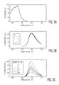
- FIG. 3A is a plot of the excitation spectrum of Ruphen
- FIG. 3B is a plot of the emission spectrum of Ruphen at different pH values
- FIG. 3C is a plot of the emission spectrum of Ruphen at different temperatures
- FIG. 3D is a plot of the excitation spectrum of APTS
- FIG. 3E is a plot of the emission spectrum of APTS at different pH values
- FIG. 3F is a plot of the emission spectrum of APTS at different temperatures
- FIG. 4 is a schematic diagram of a system used to measure the effect of temperature on a luminescence-based gel sensor made up of a Ruphen containing hydrogel and an APTS containing hydrogel, in accordance with one embodiment of the present invention
- FIG. 5 is a schematic diagram of one preferred embodiment of the LED controller shown in FIG. 4 ;
- FIG. 6 is a flowchart showing preferred key functional steps executed by the controller 140 for a scenario where the Ruphen containing hydrogel and APTS containing hydrogel that make up the luminescence-based gel sensor are positioned adjacent to each other or otherwise spatially separated from each other, such their emission signals are spatially separated when they reach the detector;
- FIG. 7 are plots showing the ratio of fluorescence intensity of Ruphen to APTS as a function of temperature
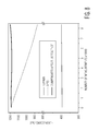
- FIG. 8 is a plot showing the decrease in fluorescence of Ruphen and APTS due to bleaching effects.
- FIG. 9 is a schematic diagram of an incubator/radiant warmer that incorporates a remote body temperature sensing system, in accordance with an embodiment of the present invention.
- the present invention will be described in connection with a noninvasive remote temperature sensor and sensing method that is particularly suited for the remote sensing of skin temperature in infants.
- the present invention can be used as a remote sensor for other types of parameters such as, for example, CO2, pH, ammonia, oxygen, sodium, calcium and potassium.
- luminophore and fluorophore are used interchangeably and both refer to a chemical compound that re-emits light upon light excitation.
- the present invention utilizes luminescence-based sensing.
- a temperature sensing luminophore is incorporated in a soft hydrogel that can then be applied gently on human skin. The adhesion on the skin is strong enough that it does not fall off, but can also be gently wiped off at the conclusion of temperature measurements.
- luminophores have been found to show high sensitivity to temperature. The luminescence intensities and decay times of these compounds decrease with increasing temperatures and can be measured with a high degree of accuracy. Thus, many luminophores have been previously utilized as luminescent temperature probes. However, most of these are not suitable for healthcare applications, particularly neonatal healthcare applications. As an example, alexandrite crystals have been found to be sensitive between 15°-45° C., and the phosphorescence decay time decreases from 300 to 220 microseconds within this range. The long decay time is easy to precisely measure with low cost instrumentation. While these properties may seem appropriate for healthcare applications, alexandrite crystals cannot be ground to a fine powder for application on human skin. Additionally, the grinding process creates defects on the crystal structure which render alexandrite non-luminescent.
- luminophores that are excitable by visible light, such as ruthenium(II) tris(1, 10-phenanthroline) (Ruphen) and ruthenium(II) tris(bipyridine) (Rubpy). These dyes are not only highly luminescent, but their luminescence intensity and decay times are also very sensitive to temperature. Moreover, they have been found to be nontoxic and incapable of penetrating human skin.
- Luminescence-based temperature probes have a variety of advantages over thermoelectric probes, including immunity to high electromagnetic fields, the suitability for long distance measurements, and virtually unlimited spatial resolution.
- luminophores can be employed in thermal convection studies in both huge bioreactors and micro-sized lab-on-a-chip environments.
- the probe and the photodetector need not to be in direct contact. Accordingly, remote detection can be realized. Due to the advantages of luminescence sensors, a number of luminescence-based temperature probes have been developed.
- FIG. 1 is a schematic diagram of a noninvasive remote parameter sensing system 100 that utilizes a luminescence-based sensor 110 , in accordance with one embodiment of the present invention.
- the remote parameter sensing system 100 includes a luminescence-based sensor 110 , a light source 120 , a detector 130 and a controller 140 .
- the luminescence-based sensor 110 is in contact with a surface 150 where the parameter, such as temperature, is to be measured, and is preferably a gel that is embedded with a chemical that emits light 160 , via luminescence, when it is excited by excitation light 170 from the light source 120 at an appropriate excitation frequency.
- the chemical properties of the luminescence-based sensor 110 are such that at least one characteristic of the emission light 160 (such as, for example, emission intensity) varies as a function of variations in the parameter being measured.
- the controller 140 controls the measurement process, including control of the light source 120 , receiving detector signals from the detector 130 and processing and analyzing the detector signals to analyze the parameter being measured.
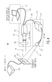
- FIG. 2 is a schematic diagram of a system 200 for remotely and noninvasively monitoring body temperature utilizing one or more luminescence-based gel sensors 110 , in accordance with another embodiment of the present invention.
- the system 200 includes a light source 120 , detector 130 , controller 140 , and at least one luminescence-based gel sensor 110 placed on the skin 210 of the subject whose temperature is being measured.
- the luminescence-based gel sensors 110 are preferably applied onto multiple sites on the subject's skin 210 .
- the luminescence-based gel sensors are illuminated from a distance with excitation light 170 from light source 120 , and the emission light 160 is detected by detector 130 .
- the detector signals are then analyzed by controller 140 .
- the detector 130 is a movable CCD camera and the controller 140 is programmed with shape recognition software for controlling the position of the CCD camera to follow the luminescence-based gel sensors 110 as the subject moves.
- the temperature sensing system 200 offers many advantages of over existing systems. First, there is no need for problematic adhesives to keep the luminescence-based gel sensors 110 in place. It is very easy to daub the luminescence-based gel sensors 110 on the skin 210 , and the luminescence-based gel sensors 110 can be removed easily by gentle wiping with a wet tissue. Thus, the skin 210 will not be exposed to any stress associated with applying and removing an adhered probe.
- luminescence-based gel sensors 110 can be smeared anywhere and at multiple points on the subject. In contrast, taking temperature readings at multiple points with wired thermistors can be very cumbersome, and creates the added danger of an infant getting caught in a tangle of wires. Further, as the luminescence-based gel sensors 110 are always in close contact with the skin 210 , optimal heat transfer from the skin 210 to the luminescence-based gel sensors 110 are ensured at all times, thereby increasing the accuracy of the temperature measurement and its correlation to core body temperature.
- the luminescence-based gel sensors 110 in system 200 are preferably designed to be excited with and emit light in the visible wavelength range.
- the luminescence-based gel sensors 110 are preferably temperature sensitive nontoxic luminophores in a hydrogel matrix.
- the preferred properties of the luminophores and hydrogel matrix will now be discussed.
- Approach (2) takes the intensity ratio of two emission bands of the luminophore system to represent the temperature. Assuming the photobleaching effect has the same impact on the emission bands, the ratio is unaffected, thereby making the system less prone to drift.
- Approach (3) utilizes the decay time of the luminophore as the temperature sensitive parameter.
- the decay time is the time span required for the luminophore dye at the excited state to return to the electronic ground state. This transition is temperature dependent. Since it is an intrinsic property of the dye molecule, the temperature measurement based on the decay time technique is entirely independent of the luminophore concentration.
- the luminescence process is initiated by the absorption of light by the ground state luminophore, and in the process promoting the molecule to an electronic excited state.
- the ruthenium luminophores mentioned above (Ruphen and Rubpy) undergo intersystem crossing from the lowest singlet excited state to the triplet state (technically a singlet-triplet hybrid), which is normally at a lower energy. Return of the triplet to the singlet ground state requires intersystem crossing, i.e. a “forbidden” process. This explains both the long decay lifetimes, as well as the red-shifted emission.
- the luminescence-based gel sensor 110 is made up of two different types of fluorophores in a hydrogel matrix.
- the two fluorophores are preferably Ruphen and 8-aminopyrene-1,3,6-trisulfonic acid (“APTS”).
- the fluorophores Ruphen and APTS are an ideal fluorophore pair for ratiometric temperature measurement.
- Ruphen the ruthenium ion Ru(II) forms an octahedral complex with three phenanthroline molecules.
- the complex has a strong absorption band at around 450 nm due to the very prominent metal to ligand charge transfer transition (MLCT) to the triplet MLCT state that is energetically slightly lower than the triplet d-d state.
- MLCT metal to ligand charge transfer transition
- the transition from the MLCT state to the ground state results in emission of light (at 590 nm) whereas the promotion to the d-d state by thermal energy leads to the radiationless decay to the ground state.
- APTS is a polycyclic aromatic compound consisting of 4 fused benzene rings.
- the excitation maximum is at around 420 nm in aqueous solution, whereas the emission peak is located at 500 nm.
- both dyes can be excited by visible blue light, which is harmless to human skin and, therefore, acceptable for use on humans.
- an inexpensive but efficient LED can be employed as a single excitation light source 120 .
- the emission peaks of Ruphen ( FIGS. 3B and 3C ) and APTS ( FIGS. 3E and 3F ) are about 90 nm apart. Accordingly, they can be easily isolated with the appropriate filters. Moreover, the fluorescence of Ruphen and APTS are only slightly affected by pH, as shown in FIGS. 3B and 3E , respectively. This is important, as the skin of neonates at different gestational ages have varying pH levels.
- ambient temperature has varying impacts on the fluorescence of the two dyes.
- the fluorescence intensity of Ruphen drops drastically by 75 per cent when the ambient temperature is changed from 25° C. to 50° C.
- the significant temperature sensitivity in the physiological range makes Ruphen an ideal body temperature sensor.
- the same temperature change has virtually no impact on the fluorescence of APTS, as shown in FIG. 3F .
- APTS makes a very good reference sensor for Ruphen in ratiometric temperature measurements.
- the luminescence-based gel sensor 110 preferably utilizes a skin-friendly vehicle or matrix for the luminophore dyes.
- the matrix in which the sensing luminophores are incorporated is a replacement for the harmful adhesive currently used to keep thermistors in place.
- the matrix provides several important functions. It is the affixing component that enables contact of the luminophore dyes with the skin 210 . It encapsulates the dyes within a semi-solid structure preventing the dyes from being blown off (if powder) or wiped off (if liquid) from the skin 210 . The matrix also provides good heat transfer from the skin/body to the temperature sensing luminophore dyes, allowing for precise body temperature measurements to be carried out.
- the matrix In order to be used as a temperature sensor on a human subject, the matrix should be biocompatible, should not harbor harmful microorganisms and should be non-irritating to the skin 210 . Also, the matrix should not excessively absorb heat from the radiant warmer in the incubator or other sources, as this can cause a temperature reading higher than the skin temperature. Further, while the matrix should adhere well to the skin 210 , it should be easily removable without irritating or harming the skin 210 .
- inorganic (metals, ceramics, and glasses) and polymeric (synthetic and natural) materials have been used for such items as artificial heart-valves, (polymeric or carbon-based) and synthetic blood-vessels.
- polymeric materials typically include hydrogels.
- Hydrogels are a network of polymer chains that are water-insoluble and are highly absorbent. They can contain over 99% water, which makes them highly flexible like natural tissue. Applications for hydrogels cover a wide range of fields. For example, polylactic acids are used as scaffolds in tissue engineering, 2-hydroxypropyl-methacrylate polymers (HPMA) has been widely employed in drug delivery systems, and polyacrylic acid is used as the super-absorbent in disposable diapers. In addition, contact lenses are made from silicone or polyacrylamide (15).
- hydrogels used for wound dressings have the desired properties suitable for the sensitive skin of neonates. As such, they create or maintain a moist environment so that the skin 210 cannot dry out. They are well permeable to oxygen, so that the skin 210 underneath can breathe. In addition, these hydrogels protect wounds from the entry of microbes. Moreover, they adhere firmly even on the wounds, and can be gently removed without irritation.
- Glyceryl polyacrylate (GPA) and chitosan are the subjects of active research as antibacterial wound dressing gels.
- Chitosan is a linear polysaccharide composed of randomly distributed ⁇ -(1-4)-linked D-glucosamine and N-acetyl-D-glucosamine produced commercially by de-acetylation of chitin, the structural element in the exoskeleton of crustaceans (crabs, shrimp, etc.) and cell walls of fungi.
- the amino group in chitosan has a pKa value of ⁇ 6.5, thus, chitosan is positively charged and soluble in acidic to neutral solution with a charge density dependent on pH and the deacetylation value. This makes chitosan and its derivatives a bio-adhesive which readily binds to negatively charged surfaces, such as mucosal membranes.
- Chitosan and its derivatives are approved to be hypoallergenic and antibacterial. Its high tensile and bioadhesive strength are advantageous for forming a tacky sensing layer. Further, it can be gently dissolved by a slightly acidic solution at pH 6.0.
- Glyceryl polyacrylate is a clathrate gel known for its high water retention ability. It does not dry even when exposed to ambient air or subjected to vacuum for 48 hours. This property is particularly useful for inactivating microbes by depriving them of water through osmotic effect. Studies show that by adding a certain amount of glycerol, the viscosity of the gel can be controlled. This results in a product that can adhere well on the skin 210 but that can also be easily peeled off.
- chitosan gel is preferably used as the hydrogel matrix in the luminescence-based gel sensor 110 .
- the chitosan gel is preferably prepared as follows. Chitosan (medium molecular weight, Sigma) is dissolved in 0.1 M acetic acid (Sigma) to make a 2% w/v gel. To each gram of this gel, 0.5 g glycerol is added. To prepare the gels containing the fluorophores, 0.1 g of silica gel adsorbed with either Ruphen or APTS is added to 1 gram of the chitosan.
- the luminescence-based gel sensor 110 preferably includes both a Ruphen containing gel and an APTS containing gel.
- the present invention preferably uses ratiometric measurements to measure temperature using the luminescence-based gel sensor 110 .
- the ratiometric method has the advantage that the imaging system, as well as the data acquisition and processing system, need not be very sophisticated and fast. However, two luminescence signatures need to be measured to arrive at the ratio.
- FIG. 4 is a schematic diagram of a system 300 used to measure the effect of temperature on a luminescence-based gel sensor 110 made up of a Ruphen containing hydrogel and an APTS containing hydrogel.
- the system 300 includes a thermal block 310 on which the luminescence-based gel sensor 110 is placed.
- a temperature controller 320 is used to control the temperature of the thermal block 310 .
- a light source 120 that includes an LED 330 and an LED controller 340 is used to generate excitation light 170 .
- a detector 130 that includes a CCD camera 350 is used to detect the emission light 160 from the luminescence-based gel sensor 110 .
- the LED is preferably a blue LED with an excitation peak at 475 nm.
- the CCD camera 350 is controlled by controller 140 .
- Controller 140 includes a computer 360 that is connected to the CCD camera 350 via cable 365 .
- the CCD camera 350 transmits image data to and receives control commands from the computer 360 .
- the CCD camera 350 is connected to the LED controller 340 via cable 370 .
- the CCD camera 350 sends a timing signal to the LED controller 340 representing the time the CCD camera 350 makes an exposure. This timing signal is used to switch the LED 330 on and off.
- the emission light from the Ruphen and the emission light from the APTS will spatially overlap at the CCD camera 350 .
- two different band pass filters must be used to isolate the Ruphen and APTS emission light.
- This can be suitably implemented incorporating a switchable band pass filter 380 in detector 130 that switches between a first band pass filter designed to pass the emission light from the Ruphen and a second band pass filter designed to pass the emission light from the APTS.
- the switchable filter 380 can be, for example, a filter wheel.
- Another approach to discriminate between two spatially overlapping emission signals is a technique based on the decay time difference between two luminophores.
- the modulated luminescence decreases with increasing modulation frequencies, eventually reaching a certain frequency where the luminescence is completely diminished (i.e., demodulated).
- MCP multi-channel plate
- the controller 140 of system 300 preferably utilizes lock-in imaging for decay time measurements. This enables decay time measurements for a fraction of the cost and space of an MCP.
- the Ruphen containing hydrogel and APTS containing hydrogel that make up the luminescence-based gel sensor 110 are positioned adjacent to each other or otherwise spatially separated from each other such their emission signals are spatially separated when they reach the CCD camera 350 , and the CCD camera 350 can simultaneously image the emission light from both the Ruphen and APTS without the need for the switchable band pass filter 380 .
- the LED 330 is switched on and off by the CCD camera 350 as follows.
- the LED controller 340 preferably includes a microcontroller 400 and an LED driver 410 .
- the IO-port of the CCD camera 350 is connected to two external interrupt pins 410 a and 420 b on the microcontroller 400 .
- the first interrupt responds to the rising edge of the camera output signal.
- the microcontroller 400 activates the current source by setting its PWM input pin at high, which then turns the LED 330 on.
- the second interrupt is responsive to the falling edge and turns the LED 330 off.
- the microcontroller 400 is preferably programmed to turn on the LED 330 on every second camera signal. This enables the camera to take alternately one image with LED excitation light and one image with no LED excitation light, which is important for the cancellation of noise caused by ambient light.
- This control and image analysis software can be suitably implemented with the LabVIEW programming platform (LabVIEW 2010+Vision module) sold by National Instruments.
- FIG. 6 shows the preferred key functional steps of the control and image analysis software for the scenario where the Ruphen containing hydrogel and APTS containing hydrogel that make up the luminescence-based gel sensor 110 are positioned adjacent to each other or otherwise spatially separated from each other, such their emission signals are spatially separated when they reach the CCD camera 350 .
- the process starts at step 500 , where the CCD camera 350 is set at continuous acquisition mode (typically 30 frames per second), the CCD camera 350 exposure time is preferably set to 16 ms and the CCD camera 350 resolution is preferably set at 640 ⁇ 480.
- two sequential image frames are acquired from the CCD camera 350 .
- the LED controller 340 ensures the first image frame is with the LED 330 off and the second image frame is with the LED 330 on.
- the first image frame corresponds to the intensity of the ambient light only
- second image frame corresponds to the intensity of the ambient light plus the fluorescence from the luminescence-based gel sensor 110 .
- the process identifies the regions in the first image frame that correspond to the Ruphen emission (ROI 1 a ) and the APTS emission (ROI 1 b ), respectively.
- the process identifies the regions in the second image frame that correspond to the Ruphen emission (ROI 2 a ) and the APTS emission (ROI 2 b ), respectively.
- pixel values for ROI 1 a are subtracted from pixel values for ROI 2 a.
- pixel values for ROI 1 b are subtracted from pixel values for ROI 2 b. This effectively reduces or eliminates the contribution of ambient light to the pixel values, such that only the contribution from the Ruphen and APTS fluorescence emission remain.
- the average Ruphen fluorescence and APTS fluorescence per pixel, respectively, is calculated. This is suitably done by extracting the images of the Ruphen and APTS fluorescent gels, and then manually setting the spatial coordinates of the Ruphen and APTS fluorescent gel images.
- the ratio of the average Ruphen fluorescence per pixel to the average APTS fluorescence per pixel is calculated.
- the ratio is preferably subjected to a 90 point moving average filter, which minimizes possible influence of rapid changes in illumination (e.g., people walking close the luminescence-based gel sensor 110 ). This moving average filtering yields an average ratio 630 .
- This average ratio is then linearly scaled to temperature at step 640 .
- the temperature value can then be saved as a text file (step 650 ), displayed as a digital value on a digital display (step 660 ) and/or displayed as a time graph (step 670 ).
- the user has the option to change various parameters including, but not limited to, the exposure time of the CCD camera 350 (frame rate), the resolution of the CCD camera 350 , the parameters of the digital filtering step 620 .
- the system 300 of FIG. 4 was used to determine the effect of temperature changes on the luminescence-based gel sensor 110 .
- the ratio of the fluorescence intensity of Ruphen and APTS correlates linearly to the temperature of the thermal block 310 .
- the luminescence-based gel sensor 110 has a resolution of 0.0032 ° C.
- Photobleaching is an intrinsic property of the luminophores and is influenced by the presence of oxidants, such as oxygen. Since the luminescence-based gel sensor 110 employs two different luminophores, their bleaching rates will differ from one another. As shown in FIG. 8 , the fluorescence of APTS drops almost linearly by 25% from its original value after 8 hours of illumination, while the fluorescence of Ruphen remains virtually unchanged. This divergence could lead to a significant drift of the measurement signal if no compensation measures are undertaken. To correct this discrepancy, a compensation loop is preferably implemented in the control and image analysis software. The compensation algorithm takes into consideration the exposure time of the luminophore to the blue LED excitation light and compensates for the drop of the APTS fluorescence.
- the ambient oxygen concentrations are constant within the duration of the measurements.
- the software compensated for the decrease in fluorescence of APTS over an 8-hour period to a satisfactory extent.
- the average compensated value is 1189.9 and its standard deviation is ⁇ 4.21.
- the luminescence-based gel sensor 110 of the present invention is particularly suitable as a remote body temperature sensing system in incubators and radiant warmers 700 for infant and neonatal care, as shown in FIG. 9 . Temperature measurements can be taken remotely without the need for the standard adhesive thermistors that can irritate or damage the baby's skin.
- the luminescence-based gel sensors 110 are easy to apply and remove without the risk of damaging the baby's skin. Further, the luminescence-based gel sensors 110 do not require a wired connection, thereby eliminating the risk of the baby getting tangled in wires.
- the remote body temperature system can operate in the visible spectrum, there is no detector interference from the radiant warmers used in incubators and radiant warmers.
Landscapes
- Life Sciences & Earth Sciences (AREA)
- Health & Medical Sciences (AREA)
- Medical Informatics (AREA)
- Biophysics (AREA)
- Pathology (AREA)
- Engineering & Computer Science (AREA)
- Biomedical Technology (AREA)
- Heart & Thoracic Surgery (AREA)
- Physics & Mathematics (AREA)
- Molecular Biology (AREA)
- Surgery (AREA)
- Animal Behavior & Ethology (AREA)
- General Health & Medical Sciences (AREA)
- Public Health (AREA)
- Veterinary Medicine (AREA)
- Investigating, Analyzing Materials By Fluorescence Or Luminescence (AREA)
Abstract
Description
- This application is a continuation-in-part of U.S. patent application Ser. No. 13/501,081, filed Apr. 9, 2012. This application also claims priority to U.S. Provisional Application Ser. No. 61/502,542, filed Jun. 29, 2011, whose entire disclosure is incorporated herein by reference.
- 1. Field of the Invention
- The present invention relates to the noninvasive, remote sensing of predetermined parameters such as, for example, remote sensing of human body temperature.
- 2. Background of the Related Art
- Internal body temperature is a physiologic variable that is precisely controlled by the body. Chemical processes and enzymes required to catalyze the associated chemical reactions, thereby regulating cellular function, optimally operate within this narrow thermal bandwidth. Thermoregulation encompasses all physiological processes and responses that balance heat production and heat loss to maintain body temperature within this normal range. Compared to the adult or older pediatric model, thermoregulation is even more critical to neonatal care.
- Compared to adults, newborns are particularly vulnerable to temperature extremes. If heat loss is not preempted, newborns could suffer the ill effects of cold stress or hypothermia. Depending on the gestational age, mortality may increase by 10% for each degree Celsius (° C.) that a baby's body temperature is below 36° C. Conversely, at relatively high temperatures, infants may be subjected to the dangers of heat stress or hyperthermia. Both types of thermal stresses, hypo- and hyperthermia can be a significant cause of morbidity and mortality in this vulnerable population. Thus, in the hospital setting, infant incubators are designed to keep the infant in an environment of constant temperature.
- Nonetheless, providing optimal thermal conditions to the newborn require the body temperature to be measured. To date, wired thermistors are conventionally employed that are attached to a neonate's skin using a strong adhesive to keep them in place. However, adhesive use on the thermistor probe cover is not an innocuous intervention. Investigations have shown increased microbial growth beneath probe covers, some of which have proved to be pathogenic. Others have found skin impairment ranging from chemical sensitivities to prolonged mechanical force on the skin from some adhesives. Adhesives can irritate the skin by occlusion or by altering the skin morphology via epidermal stripping. The removal of adhesively-attached skin temperature probes can result in “skin tears” in which shear or frictional forces separate the dermis from the epidermis.
- These tears can compromise skin barrier function, cause a marked increase in transepidermal water loss and, in many cases, disrupt the skin's ability to protect against microorganism invasion. Especially for extremely premature neonates, the adhesive poses a high potential risk of injury due to their immature skin. Studies have shown that at 24 weeks gestation, premature neonates have little stratum corneum and attenuated rete ridges. Their skin is red, wrinkled, translucent, and gelatinous in appearance. They lack subcutaneous tissue, therefore, their dermis is lying directly over the muscle. Consequently, skin stripping secondary to adhesive dressing and/or tape removals can result in full-thickness tissue loss.
- Even at 36 weeks (full term), the epidermal and dermal layers of neonates, although structurally similar to an adult, are just up to 60% as thick as those in an adult. As a result, epidermal stripping secondary to tape and adhesive dressing removal is most common in neonates born before 27 weeks gestation and is the primary cause of skin breakdown in the Neonatal Intensive Care Unit (NICU). Given the neonate's attenuated rete ridges, adhesive products typically bond more aggressively to the epidermis than the epidermis does to the dermis. Consequently, epidermal stripping is not only a source of discomfort, but can also lead to other morbidity in very low birth weight neonates and those who are immune-compromised.
- Skin friendly adhesives that can hold the wired probe in place while minimizing trauma to the skin have not yet been developed. Alternative temperature probes that can eliminate adhesives also are nonexistent. In addition, remote thermal-imaging systems that may offer non-adhesive, non-contact features and a resolution of 0.3° C. are still too expensive for general use in the NICU.
- An object of the invention is to solve at least the above problems and/or disadvantages and to provide at least the advantages described hereinafter.
- Therefore, an object of the present invention is to provide a system and method for the remote sensing of a parameter, such as temperature, in a non-invasive and/or non-contact manner.
- Therefore, an object of the present invention is to provide a system and method for the remote sensing of a parameter, such as temperature, in a non-invasive and/or non-contact manner.
- Another object of the present invention is to provide a system and method for remotely measuring body temperature in a non-invasive and/or non-contact manner.
- Another object of the present invention is to provide a system and method for remotely measuring the body temperature of an infant in a non-invasive and/or non-contact manner.
- Another object of the invention is to provide a luminescence-based temperature sensor and sensing method;
- Another object of the invention is to provide a luminescence-based gel sensor that can be gently applied to and removed from human skin;
- To achieve at least the above objects, in whole or in part, there is provided a noninvasive remote sensor for measuring a parameter of a system, comprising a gel, and a first type of fluorophore embedded in the gel, wherein the first type of fluorophore emits first emission light in response to excitation light, and wherein a chemical property of the type of fluorophores is such that at least one characteristic of the first emission light varies as a function of changes in the parameter being measured.
- To achieve at least the above objects, in whole or in part, there is also provided a sensor for remotely monitoring the temperature of an object, comprising a gel adapted to be applied to the object, and a first type of fluorophore embedded in the gel, wherein the first type of fluorophore emits first emission light in response to excitation light, and wherein a chemical property of the first type of fluorophore is such that at least one characteristic of the first emission light varies as a function of temperature.
- To achieve at least the above objects, in whole or in part, there is also provided a method of monitoring skin temperature, comprising applying a luminescence-based gel sensor to skin, wherein the luminescence-based gel sensor comprises a first type of fluorophore embedded in a gel, illuminating the luminescence-based gel sensor with excitation light, detecting emission light from the first type of fluorophore, and determining the skin temperature based on the detected emission light.
- Additional advantages, objects, and features of the invention will be set forth in part in the description which follows and in part will become apparent to those having ordinary skill in the art upon examination of the following or may be learned from practice of the invention. The objects and advantages of the invention may be realized and attained as particularly pointed out in the appended claims.
- The invention will be described in detail with reference to the following drawings in which like reference numerals refer to like elements wherein:
-
FIG. 1 is a schematic diagram of a noninvasive remote parameter sensing system that utilizes a luminescence-based sensor, in accordance with one embodiment the present invention; -
FIG. 2 is a system for remotely monitoring body temperature that utilizes a luminescence-based gel sensor, in accordance with one embodiment the present invention; -
FIG. 3A is a plot of the excitation spectrum of Ruphen; -
FIG. 3B is a plot of the emission spectrum of Ruphen at different pH values; -
FIG. 3C is a plot of the emission spectrum of Ruphen at different temperatures; -
FIG. 3D is a plot of the excitation spectrum of APTS; -
FIG. 3E is a plot of the emission spectrum of APTS at different pH values; -
FIG. 3F is a plot of the emission spectrum of APTS at different temperatures; -
FIG. 4 is a schematic diagram of a system used to measure the effect of temperature on a luminescence-based gel sensor made up of a Ruphen containing hydrogel and an APTS containing hydrogel, in accordance with one embodiment of the present invention; -
FIG. 5 is a schematic diagram of one preferred embodiment of the LED controller shown inFIG. 4 ; -
FIG. 6 is a flowchart showing preferred key functional steps executed by thecontroller 140 for a scenario where the Ruphen containing hydrogel and APTS containing hydrogel that make up the luminescence-based gel sensor are positioned adjacent to each other or otherwise spatially separated from each other, such their emission signals are spatially separated when they reach the detector; -
FIG. 7 are plots showing the ratio of fluorescence intensity of Ruphen to APTS as a function of temperature; -
FIG. 8 is a plot showing the decrease in fluorescence of Ruphen and APTS due to bleaching effects; and -
FIG. 9 is a schematic diagram of an incubator/radiant warmer that incorporates a remote body temperature sensing system, in accordance with an embodiment of the present invention. - By way of example, the present invention will be described in connection with a noninvasive remote temperature sensor and sensing method that is particularly suited for the remote sensing of skin temperature in infants. However, it should be appreciated that the present invention can be used as a remote sensor for other types of parameters such as, for example, CO2, pH, ammonia, oxygen, sodium, calcium and potassium.
- Throughout the specification, the terms luminophore and fluorophore are used interchangeably and both refer to a chemical compound that re-emits light upon light excitation.
- The present invention utilizes luminescence-based sensing. In a preferred embodiment for temperature sensing, a temperature sensing luminophore is incorporated in a soft hydrogel that can then be applied gently on human skin. The adhesion on the skin is strong enough that it does not fall off, but can also be gently wiped off at the conclusion of temperature measurements.
- A variety of luminophores have been found to show high sensitivity to temperature. The luminescence intensities and decay times of these compounds decrease with increasing temperatures and can be measured with a high degree of accuracy. Thus, many luminophores have been previously utilized as luminescent temperature probes. However, most of these are not suitable for healthcare applications, particularly neonatal healthcare applications. As an example, alexandrite crystals have been found to be sensitive between 15°-45° C., and the phosphorescence decay time decreases from 300 to 220 microseconds within this range. The long decay time is easy to precisely measure with low cost instrumentation. While these properties may seem appropriate for healthcare applications, alexandrite crystals cannot be ground to a fine powder for application on human skin. Additionally, the grinding process creates defects on the crystal structure which render alexandrite non-luminescent.
- Many other materials, such as zinc sulfide and lanthanide phosphors (e.g., La2O2S:Eu) also show strong temperature sensitivity over the desired range of temperatures. The lanthanide phosphors also show desirable lifetime changes as the temperature changes. Unfortunately, all of these luminophores are only excitable by UV light, which is potentially harmful to human skin, particularly neonatal skin.
- In contrast to UV-excited materials, there are classes of luminophores that are excitable by visible light, such as ruthenium(II) tris(1, 10-phenanthroline) (Ruphen) and ruthenium(II) tris(bipyridine) (Rubpy). These dyes are not only highly luminescent, but their luminescence intensity and decay times are also very sensitive to temperature. Moreover, they have been found to be nontoxic and incapable of penetrating human skin.
- These dyes that are excitable with visible light have been widely employed as temperature probes in various research fields. Luminescence-based temperature probes have a variety of advantages over thermoelectric probes, including immunity to high electromagnetic fields, the suitability for long distance measurements, and virtually unlimited spatial resolution. For instance, luminophores can be employed in thermal convection studies in both huge bioreactors and micro-sized lab-on-a-chip environments. Furthermore, since light transmission requires no conducting medium, the probe and the photodetector need not to be in direct contact. Accordingly, remote detection can be realized. Due to the advantages of luminescence sensors, a number of luminescence-based temperature probes have been developed.
-
FIG. 1 is a schematic diagram of a noninvasive remoteparameter sensing system 100 that utilizes a luminescence-basedsensor 110, in accordance with one embodiment of the present invention. The remoteparameter sensing system 100 includes a luminescence-basedsensor 110, alight source 120, adetector 130 and acontroller 140. The luminescence-basedsensor 110 is in contact with asurface 150 where the parameter, such as temperature, is to be measured, and is preferably a gel that is embedded with a chemical that emits light 160, via luminescence, when it is excited by excitation light 170 from thelight source 120 at an appropriate excitation frequency. The chemical properties of the luminescence-basedsensor 110 are such that at least one characteristic of the emission light 160 (such as, for example, emission intensity) varies as a function of variations in the parameter being measured. - The
controller 140 controls the measurement process, including control of thelight source 120, receiving detector signals from thedetector 130 and processing and analyzing the detector signals to analyze the parameter being measured. -
FIG. 2 is a schematic diagram of asystem 200 for remotely and noninvasively monitoring body temperature utilizing one or more luminescence-basedgel sensors 110, in accordance with another embodiment of the present invention. Thesystem 200 includes alight source 120,detector 130,controller 140, and at least one luminescence-basedgel sensor 110 placed on theskin 210 of the subject whose temperature is being measured. - The luminescence-based
gel sensors 110 are preferably applied onto multiple sites on the subject'sskin 210. The luminescence-based gel sensors are illuminated from a distance with excitation light 170 fromlight source 120, and theemission light 160 is detected bydetector 130. The detector signals are then analyzed bycontroller 140. In one preferred embodiment, thedetector 130 is a movable CCD camera and thecontroller 140 is programmed with shape recognition software for controlling the position of the CCD camera to follow the luminescence-basedgel sensors 110 as the subject moves. - The
temperature sensing system 200 offers many advantages of over existing systems. First, there is no need for problematic adhesives to keep the luminescence-basedgel sensors 110 in place. It is very easy to daub the luminescence-basedgel sensors 110 on theskin 210, and the luminescence-basedgel sensors 110 can be removed easily by gentle wiping with a wet tissue. Thus, theskin 210 will not be exposed to any stress associated with applying and removing an adhered probe. - Another advantage is the flexibility of the luminescence-based
gel sensors 110. For example, luminescence-basedgel sensors 110 can be smeared anywhere and at multiple points on the subject. In contrast, taking temperature readings at multiple points with wired thermistors can be very cumbersome, and creates the added danger of an infant getting caught in a tangle of wires. Further, as the luminescence-basedgel sensors 110 are always in close contact with theskin 210, optimal heat transfer from theskin 210 to the luminescence-basedgel sensors 110 are ensured at all times, thereby increasing the accuracy of the temperature measurement and its correlation to core body temperature. - While temperature sensing luminophores have been used in the art, they require UV light excitation, which is not acceptable for humans (particularly infants), or they emit light in the IR wavelength range where radiant warmers will interfere. The luminescence-based
gel sensors 110 insystem 200 are preferably designed to be excited with and emit light in the visible wavelength range. - As discussed above, the luminescence-based
gel sensors 110 are preferably temperature sensitive nontoxic luminophores in a hydrogel matrix. The preferred properties of the luminophores and hydrogel matrix will now be discussed. - In general, there are three approaches for measuring temperature: (1) steady state luminescence intensity measurements; (2) ratiometric intensity measurements; and (3) decay time measurements. The simplest is approach (1), which measures the steady state luminescence intensity. However, this approach is not suitable for long term measurements, as the intensity can drift due to photobleaching of the luminophore. Methods (2) and (3) offer solutions to this problem.
- Approach (2) takes the intensity ratio of two emission bands of the luminophore system to represent the temperature. Assuming the photobleaching effect has the same impact on the emission bands, the ratio is unaffected, thereby making the system less prone to drift.
- Approach (3) utilizes the decay time of the luminophore as the temperature sensitive parameter. The decay time is the time span required for the luminophore dye at the excited state to return to the electronic ground state. This transition is temperature dependent. Since it is an intrinsic property of the dye molecule, the temperature measurement based on the decay time technique is entirely independent of the luminophore concentration.
- The luminescence process is initiated by the absorption of light by the ground state luminophore, and in the process promoting the molecule to an electronic excited state. The ruthenium luminophores mentioned above (Ruphen and Rubpy) undergo intersystem crossing from the lowest singlet excited state to the triplet state (technically a singlet-triplet hybrid), which is normally at a lower energy. Return of the triplet to the singlet ground state requires intersystem crossing, i.e. a “forbidden” process. This explains both the long decay lifetimes, as well as the red-shifted emission.
- In a preferred embodiment, the luminescence-based
gel sensor 110 is made up of two different types of fluorophores in a hydrogel matrix. The two fluorophores are preferably Ruphen and 8-aminopyrene-1,3,6-trisulfonic acid (“APTS”). - The fluorophores Ruphen and APTS are an ideal fluorophore pair for ratiometric temperature measurement. In Ruphen, the ruthenium ion Ru(II) forms an octahedral complex with three phenanthroline molecules. The complex has a strong absorption band at around 450 nm due to the very prominent metal to ligand charge transfer transition (MLCT) to the triplet MLCT state that is energetically slightly lower than the triplet d-d state. The transition from the MLCT state to the ground state results in emission of light (at 590 nm) whereas the promotion to the d-d state by thermal energy leads to the radiationless decay to the ground state. These two processes compete at any given temperature. Hence, less fluorescence emission is observed at higher temperatures and vice versa.
- APTS, on the other hand, is a polycyclic aromatic compound consisting of 4 fused benzene rings. The excitation maximum is at around 420 nm in aqueous solution, whereas the emission peak is located at 500 nm. As shown on
FIGS. 3A and 3D , both dyes can be excited by visible blue light, which is harmless to human skin and, therefore, acceptable for use on humans. Additionally, an inexpensive but efficient LED can be employed as a singleexcitation light source 120. - The emission peaks of Ruphen (
FIGS. 3B and 3C ) and APTS (FIGS. 3E and 3F ) are about 90 nm apart. Accordingly, they can be easily isolated with the appropriate filters. Moreover, the fluorescence of Ruphen and APTS are only slightly affected by pH, as shown inFIGS. 3B and 3E , respectively. This is important, as the skin of neonates at different gestational ages have varying pH levels. - More importantly, ambient temperature has varying impacts on the fluorescence of the two dyes. On the one hand, as shown in
FIG. 3C , the fluorescence intensity of Ruphen drops drastically by 75 per cent when the ambient temperature is changed from 25° C. to 50° C. The significant temperature sensitivity in the physiological range makes Ruphen an ideal body temperature sensor. On the other hand, the same temperature change has virtually no impact on the fluorescence of APTS, as shown inFIG. 3F . Thus, APTS makes a very good reference sensor for Ruphen in ratiometric temperature measurements. - As discussed above, there is a need for remote and non-adhesive temperature sensing for infants. To this end, the luminescence-based
gel sensor 110 preferably utilizes a skin-friendly vehicle or matrix for the luminophore dyes. The matrix in which the sensing luminophores are incorporated is a replacement for the harmful adhesive currently used to keep thermistors in place. - The matrix provides several important functions. It is the affixing component that enables contact of the luminophore dyes with the
skin 210. It encapsulates the dyes within a semi-solid structure preventing the dyes from being blown off (if powder) or wiped off (if liquid) from theskin 210. The matrix also provides good heat transfer from the skin/body to the temperature sensing luminophore dyes, allowing for precise body temperature measurements to be carried out. - In order to be used as a temperature sensor on a human subject, the matrix should be biocompatible, should not harbor harmful microorganisms and should be non-irritating to the
skin 210. Also, the matrix should not excessively absorb heat from the radiant warmer in the incubator or other sources, as this can cause a temperature reading higher than the skin temperature. Further, while the matrix should adhere well to theskin 210, it should be easily removable without irritating or harming theskin 210. - During the last two decades, significant advances have been made in the development of biocompatible and biodegradable materials for biomedical applications. In the biomedical field, the goal is to develop and characterize artificial materials for use in the human body to measure, restore, and improve physiologic function, and enhance survival and quality of life.
- Typically, inorganic (metals, ceramics, and glasses) and polymeric (synthetic and natural) materials have been used for such items as artificial heart-valves, (polymeric or carbon-based) and synthetic blood-vessels. However, the preferred matrix for the luminophores are hydrogels.
- Hydrogels are a network of polymer chains that are water-insoluble and are highly absorbent. They can contain over 99% water, which makes them highly flexible like natural tissue. Applications for hydrogels cover a wide range of fields. For example, polylactic acids are used as scaffolds in tissue engineering, 2-hydroxypropyl-methacrylate polymers (HPMA) has been widely employed in drug delivery systems, and polyacrylic acid is used as the super-absorbent in disposable diapers. In addition, contact lenses are made from silicone or polyacrylamide (15).
- Of particular interest are hydrogels used for wound dressings, as they have the desired properties suitable for the sensitive skin of neonates. As such, they create or maintain a moist environment so that the
skin 210 cannot dry out. They are well permeable to oxygen, so that theskin 210 underneath can breathe. In addition, these hydrogels protect wounds from the entry of microbes. Moreover, they adhere firmly even on the wounds, and can be gently removed without irritation. - Glyceryl polyacrylate (GPA) and chitosan are the subjects of active research as antibacterial wound dressing gels. Chitosan is a linear polysaccharide composed of randomly distributed β-(1-4)-linked D-glucosamine and N-acetyl-D-glucosamine produced commercially by de-acetylation of chitin, the structural element in the exoskeleton of crustaceans (crabs, shrimp, etc.) and cell walls of fungi. The amino group in chitosan has a pKa value of ˜6.5, thus, chitosan is positively charged and soluble in acidic to neutral solution with a charge density dependent on pH and the deacetylation value. This makes chitosan and its derivatives a bio-adhesive which readily binds to negatively charged surfaces, such as mucosal membranes.
- Chitosan and its derivatives are approved to be hypoallergenic and antibacterial. Its high tensile and bioadhesive strength are advantageous for forming a tacky sensing layer. Further, it can be gently dissolved by a slightly acidic solution at pH 6.0.
- Glyceryl polyacrylate (GP) is a clathrate gel known for its high water retention ability. It does not dry even when exposed to ambient air or subjected to vacuum for 48 hours. This property is particularly useful for inactivating microbes by depriving them of water through osmotic effect. Studies show that by adding a certain amount of glycerol, the viscosity of the gel can be controlled. This results in a product that can adhere well on the
skin 210 but that can also be easily peeled off. - For at least the reasons set forth above, chitosan gel is preferably used as the hydrogel matrix in the luminescence-based
gel sensor 110. The chitosan gel is preferably prepared as follows. Chitosan (medium molecular weight, Sigma) is dissolved in 0.1 M acetic acid (Sigma) to make a 2% w/v gel. To each gram of this gel, 0.5 g glycerol is added. To prepare the gels containing the fluorophores, 0.1 g of silica gel adsorbed with either Ruphen or APTS is added to 1 gram of the chitosan. The luminescence-basedgel sensor 110 preferably includes both a Ruphen containing gel and an APTS containing gel. - The present invention preferably uses ratiometric measurements to measure temperature using the luminescence-based
gel sensor 110. The ratiometric method has the advantage that the imaging system, as well as the data acquisition and processing system, need not be very sophisticated and fast. However, two luminescence signatures need to be measured to arrive at the ratio. -
FIG. 4 is a schematic diagram of asystem 300 used to measure the effect of temperature on a luminescence-basedgel sensor 110 made up of a Ruphen containing hydrogel and an APTS containing hydrogel. Thesystem 300 includes athermal block 310 on which the luminescence-basedgel sensor 110 is placed. Atemperature controller 320 is used to control the temperature of thethermal block 310. Alight source 120 that includes anLED 330 and anLED controller 340 is used to generateexcitation light 170. Adetector 130 that includes aCCD camera 350 is used to detect theemission light 160 from the luminescence-basedgel sensor 110. For a luminescence-basedgel sensor 110 made up of a Ruphen containing hydrogel and an APTS containing hydrogel, the LED is preferably a blue LED with an excitation peak at 475 nm. - The
CCD camera 350 is controlled bycontroller 140.Controller 140 includes acomputer 360 that is connected to theCCD camera 350 viacable 365. TheCCD camera 350 transmits image data to and receives control commands from thecomputer 360. TheCCD camera 350 is connected to theLED controller 340 viacable 370. TheCCD camera 350 sends a timing signal to theLED controller 340 representing the time theCCD camera 350 makes an exposure. This timing signal is used to switch theLED 330 on and off. - If the Ruphen containing hydrogel and APTS containing hydrogel that make up the luminescence-based
gel sensor 110 are mixed together or are otherwise not spatially separated from each other, then the emission light from the Ruphen and the emission light from the APTS will spatially overlap at theCCD camera 350. In this scenario, two different band pass filters must be used to isolate the Ruphen and APTS emission light. This can be suitably implemented incorporating a switchableband pass filter 380 indetector 130 that switches between a first band pass filter designed to pass the emission light from the Ruphen and a second band pass filter designed to pass the emission light from the APTS. Theswitchable filter 380 can be, for example, a filter wheel. - Another approach to discriminate between two spatially overlapping emission signals is a technique based on the decay time difference between two luminophores. When a luminophore is exposed to intensity modulated excitation light, the observed luminescence intensity is dependent on the modulation frequency w and the luminophore decay time τ. This dependency is described by the following equation: ƒ=s/(1+ω2*τ2)−0.5, where s is the steady state luminescence intensity of the fluorophore, ω is the angular modulation frequency and τ is the decay time.
- According to this equation, the modulated luminescence decreases with increasing modulation frequencies, eventually reaching a certain frequency where the luminescence is completely diminished (i.e., demodulated). The longer the decay time, the lower this boundary frequency is.
- Suppose there are two luminophores in a system with a decay time difference of three orders of magnitude. When the system is excited with modulated excitation light at a frequency where the luminescence of the dye with longer decay time is demodulated, only the luminescence of the dye with shorter decay time will be observed.
- At a lower frequency, emission from both the luminophores will be observed. Thus, one can calculate the ratio of the emission at the higher and lower excitation frequencies as an alternative to intensity ratios at two wavelengths. This technique has been successfully exploited for the determination of glucose and glutamine using fluorescently labeled periplasmic binding protein sensors.
- Decay time measurements usually require sophisticated and fast performing imaging systems. Conventional methods use multi-channel plate (MCP) based image intensifiers. Unfortunately, MCPs are comparatively expensive, prone to photo-damage due to overexposure and require elaborate electronics. Moreover, MCP's spatial resolution is relatively low. Furthermore, MCPs can inject a comparatively high noise level in the measurement.
- If the decay time technique is used, the
controller 140 ofsystem 300 preferably utilizes lock-in imaging for decay time measurements. This enables decay time measurements for a fraction of the cost and space of an MCP. The decay time can be determined by a phase modulation technique. In this approach, the luminescence modulated with a frequency ω is phase shifted in comparison to the excitation light. The phase shift φ is dependent on the decay time τ by the relation τ=tan(φ)/ω. - The phase shift can be determined with images from the
CCD camera 350 as follows: Images are taken with phase delays (relative to the modulated excitation light) of 0, 0.5π, π and 1.5π. The phase shift is calculated as φ=arctan[(S1.5π−S0.5π)/S0−Sπ)]−φ′, where φ′ is the instrumental phase delay which can estimated by measuring the reflected excitation light. This technique is immune to interference from ambient light, which ensures precise temperature measurements. - If the Ruphen containing hydrogel and APTS containing hydrogel that make up the luminescence-based
gel sensor 110 are positioned adjacent to each other or otherwise spatially separated from each other such their emission signals are spatially separated when they reach theCCD camera 350, and theCCD camera 350 can simultaneously image the emission light from both the Ruphen and APTS without the need for the switchableband pass filter 380. In this mode of operation, theLED 330 is switched on and off by theCCD camera 350 as follows. - As shown in
FIG. 5 , theLED controller 340 preferably includes amicrocontroller 400 and anLED driver 410. The IO-port of theCCD camera 350 is connected to two external interruptpins 410 a and 420 b on themicrocontroller 400. The first interrupt responds to the rising edge of the camera output signal. Themicrocontroller 400 activates the current source by setting its PWM input pin at high, which then turns theLED 330 on. The second interrupt is responsive to the falling edge and turns theLED 330 off. Further, themicrocontroller 400 is preferably programmed to turn on theLED 330 on every second camera signal. This enables the camera to take alternately one image with LED excitation light and one image with no LED excitation light, which is important for the cancellation of noise caused by ambient light. - The
controller 140 inFIGS. 1 , 2 and 4 above, as well asFIG. 9 , discussed below, preferably includes control and image analysis software. This control and image analysis software can be suitably implemented with the LabVIEW programming platform (LabVIEW 2010+Vision module) sold by National Instruments. -
FIG. 6 shows the preferred key functional steps of the control and image analysis software for the scenario where the Ruphen containing hydrogel and APTS containing hydrogel that make up the luminescence-basedgel sensor 110 are positioned adjacent to each other or otherwise spatially separated from each other, such their emission signals are spatially separated when they reach theCCD camera 350. The process starts atstep 500, where theCCD camera 350 is set at continuous acquisition mode (typically 30 frames per second), theCCD camera 350 exposure time is preferably set to 16 ms and theCCD camera 350 resolution is preferably set at 640×480. - At
steps CCD camera 350. As discussed above, theLED controller 340 ensures the first image frame is with theLED 330 off and the second image frame is with theLED 330 on. In this way, the first image frame corresponds to the intensity of the ambient light only, while second image frame corresponds to the intensity of the ambient light plus the fluorescence from the luminescence-basedgel sensor 110. - At
steps ROI 1 a) and the APTS emission (ROI 1 b), respectively. Atsteps ROI 2 a) and the APTS emission (ROI 2 b), respectively. - At
step 570, pixel values forROI 1 a are subtracted from pixel values forROI 2 a. Atstep 580, pixel values forROI 1 b are subtracted from pixel values forROI 2 b. This effectively reduces or eliminates the contribution of ambient light to the pixel values, such that only the contribution from the Ruphen and APTS fluorescence emission remain. - Then, at
steps - At
step 610, the ratio of the average Ruphen fluorescence per pixel to the average APTS fluorescence per pixel is calculated. Atstep 620, the ratio is preferably subjected to a 90 point moving average filter, which minimizes possible influence of rapid changes in illumination (e.g., people walking close the luminescence-based gel sensor 110). This moving average filtering yields anaverage ratio 630. - This average ratio is then linearly scaled to temperature at
step 640. The temperature value can then be saved as a text file (step 650), displayed as a digital value on a digital display (step 660) and/or displayed as a time graph (step 670). The user has the option to change various parameters including, but not limited to, the exposure time of the CCD camera 350 (frame rate), the resolution of theCCD camera 350, the parameters of thedigital filtering step 620. - The
system 300 ofFIG. 4 was used to determine the effect of temperature changes on the luminescence-basedgel sensor 110. As shown inFIG. 7 , within a physiologically relevant temperature range, the ratio of the fluorescence intensity of Ruphen and APTS correlates linearly to the temperature of thethermal block 310. Based on this data, the luminescence-basedgel sensor 110 has a resolution of 0.0032 ° C. - Photobleaching is an intrinsic property of the luminophores and is influenced by the presence of oxidants, such as oxygen. Since the luminescence-based
gel sensor 110 employs two different luminophores, their bleaching rates will differ from one another. As shown inFIG. 8 , the fluorescence of APTS drops almost linearly by 25% from its original value after 8 hours of illumination, while the fluorescence of Ruphen remains virtually unchanged. This divergence could lead to a significant drift of the measurement signal if no compensation measures are undertaken. To correct this discrepancy, a compensation loop is preferably implemented in the control and image analysis software. The compensation algorithm takes into consideration the exposure time of the luminophore to the blue LED excitation light and compensates for the drop of the APTS fluorescence. It is also assumed that the ambient oxygen concentrations are constant within the duration of the measurements. As can be seen inFIG. 8 , the software compensated for the decrease in fluorescence of APTS over an 8-hour period to a satisfactory extent. The average compensated value is 1189.9 and its standard deviation is ±4.21. - The luminescence-based
gel sensor 110 of the present invention is particularly suitable as a remote body temperature sensing system in incubators andradiant warmers 700 for infant and neonatal care, as shown inFIG. 9 . Temperature measurements can be taken remotely without the need for the standard adhesive thermistors that can irritate or damage the baby's skin. The luminescence-basedgel sensors 110 are easy to apply and remove without the risk of damaging the baby's skin. Further, the luminescence-basedgel sensors 110 do not require a wired connection, thereby eliminating the risk of the baby getting tangled in wires. In addition, because the remote body temperature system can operate in the visible spectrum, there is no detector interference from the radiant warmers used in incubators and radiant warmers. - The foregoing embodiments and advantages are merely exemplary, and are not to be construed as limiting the present invention. The present teaching can be readily applied to other types of apparatuses. The description of the present invention is intended to be illustrative, and not to limit the scope of the claims. Many alternatives, modifications, and variations will be apparent to those skilled in the art. Various changes may be made without departing from the spirit and scope of the invention, as defined in the following claims. For example, although the luminescence-based gel sensors have been described in connection with a remote body temperature sensing system, it can be adapted for the remote sensing of other parameters by choosing the appropriate light sources and luminescence-based gel sensors.
Claims (30)
Priority Applications (1)
| Application Number | Priority Date | Filing Date | Title |
|---|---|---|---|
| US13/539,067 US9560974B2 (en) | 2011-06-29 | 2012-06-29 | Luminescence based noninvasive remote parameter sensor and sensing method |
Applications Claiming Priority (3)
| Application Number | Priority Date | Filing Date | Title |
|---|---|---|---|
| US201161502542P | 2011-06-29 | 2011-06-29 | |
| US13/539,067 US9560974B2 (en) | 2011-06-29 | 2012-06-29 | Luminescence based noninvasive remote parameter sensor and sensing method |
| US201213501081A | 2012-07-23 | 2012-07-23 |
Related Parent Applications (1)
| Application Number | Title | Priority Date | Filing Date |
|---|---|---|---|
| US201213501081A Continuation-In-Part | 2011-06-29 | 2012-07-23 |
Publications (2)
| Publication Number | Publication Date |
|---|---|
| US20130079661A1 true US20130079661A1 (en) | 2013-03-28 |
| US9560974B2 US9560974B2 (en) | 2017-02-07 |
Family
ID=47912031
Family Applications (1)
| Application Number | Title | Priority Date | Filing Date |
|---|---|---|---|
| US13/539,067 Expired - Fee Related US9560974B2 (en) | 2011-06-29 | 2012-06-29 | Luminescence based noninvasive remote parameter sensor and sensing method |
Country Status (1)
| Country | Link |
|---|---|
| US (1) | US9560974B2 (en) |
Cited By (4)
| Publication number | Priority date | Publication date | Assignee | Title |
|---|---|---|---|---|
| US20170182282A1 (en) * | 2014-05-09 | 2017-06-29 | Rensselaer Polytechnic Institute | Luminous roof for nicu incubators for regulating circadian rhythms in infants and for providing high visibility of infant anatomy for healthcare staff |
| US10395134B2 (en) * | 2013-07-26 | 2019-08-27 | University Of Utah Research Foundation | Extraction of spectral information |
| CN113288676A (en) * | 2021-06-21 | 2021-08-24 | 中国人民解放军陆军特色医学中心 | Energy-saving newborn radiation rescue platform and working method thereof |
| WO2022232220A1 (en) * | 2021-04-27 | 2022-11-03 | Cynosure, Llc | Device for real-time non-contact skin temperature measurement |
Families Citing this family (5)
| Publication number | Priority date | Publication date | Assignee | Title |
|---|---|---|---|---|
| US10793772B1 (en) | 2020-03-13 | 2020-10-06 | Accelovant Technologies Corporation | Monolithic phosphor composite for sensing systems |
| US11359976B2 (en) | 2020-10-23 | 2022-06-14 | Accelovant Technologies Corporation | Multipoint surface temperature measurement system and method thereof |
| CA3137183C (en) | 2020-11-05 | 2024-02-20 | Accelovant Technologies Corporation | Optoelectronic transducer module for thermographic temperature measurements |
| US11882366B2 (en) | 2021-02-26 | 2024-01-23 | Hill-Rom Services, Inc. | Patient monitoring system |
| US12176105B2 (en) | 2021-08-23 | 2024-12-24 | Hill-Rom Services, Inc. | Patient monitoring system |
Citations (6)
| Publication number | Priority date | Publication date | Assignee | Title |
|---|---|---|---|---|
| US4323077A (en) * | 1980-03-12 | 1982-04-06 | General Electric Company | Acoustic intensity monitor |
| WO1993018745A1 (en) * | 1992-03-23 | 1993-09-30 | Geda International S.A. | Use of antiviral coating for latex items such as condoms |
| US20050112151A1 (en) * | 2003-11-20 | 2005-05-26 | Horng Liou L. | Skin adherent hydrogels |
| US20110048946A1 (en) * | 2008-02-28 | 2011-03-03 | Desai Umesh R | Method for finger-printing heparins |
| US8005624B1 (en) * | 2004-04-26 | 2011-08-23 | Starr Life Sciences Corp. | Medical devices and techniques for rodent and small mammalian based research |
| US20120330126A1 (en) * | 2009-12-23 | 2012-12-27 | Delta, Dansk Elektronik, Lys Og Akustik | Monitoring device for attachment to a surface of a subject |
Family Cites Families (15)
| Publication number | Priority date | Publication date | Assignee | Title |
|---|---|---|---|---|
| GB8513538D0 (en) | 1985-05-29 | 1985-07-03 | Mackay C D | Electrophoresis |
| US5580527A (en) | 1992-05-18 | 1996-12-03 | Moltech Corporation | Polymeric luminophores for sensing of oxygen |
| US5708957A (en) | 1996-02-02 | 1998-01-13 | University Of Iowa Research Foundation | Optical sensor with radioluminescent light source |
| US20080131512A1 (en) | 1996-07-01 | 2008-06-05 | Wilhelmus Everhardus Hennink | Biodegradable hydrogels |
| US6123455A (en) | 1997-05-02 | 2000-09-26 | American Iron And Steel Institute | Phosphor thermometry system |
| US6285807B1 (en) | 1998-11-16 | 2001-09-04 | Trustees Of Tufts College | Fiber optic sensor for long-term analyte measurements in fluids |
| AT409451B (en) | 1999-12-14 | 2002-08-26 | Hoffmann La Roche | DEVICE FOR DETERMINING THE LOCAL DISTRIBUTION OF A MEASURED VALUE |
| US6847913B2 (en) | 2001-10-04 | 2005-01-25 | The Johns Hopkins University | Ambulatory surface skin temperature monitor |
| US7364539B2 (en) | 2003-10-21 | 2008-04-29 | General Electric Company | Telemetry sensing system for infant care apparatus |
| US20050148003A1 (en) | 2003-11-26 | 2005-07-07 | Steven Keith | Methods of correcting a luminescence value, and methods of determining a corrected analyte concentration |
| EP1593946B1 (en) | 2004-05-04 | 2011-06-22 | Fisher & Paykel Healthcare Limited | Skin patch including a temperature sensor |
| WO2007043973A1 (en) | 2005-10-13 | 2007-04-19 | Dso National Laboratories | Method of enhancing a fluorescent signal |
| US7432069B2 (en) | 2005-12-05 | 2008-10-07 | Sontra Medical Corporation | Biocompatible chemically crosslinked hydrogels for glucose sensing |
| US7575890B2 (en) | 2006-01-18 | 2009-08-18 | Oxygen Enterprises, Ltd. | Method for rapid detection and evaluation of cultured cell growth |
| ATE413836T1 (en) | 2006-07-24 | 2008-11-15 | Eyesense Ag | DEVICE FOR MEASURING AN ANALYTE IN AN EYE FLUID |
-
2012
- 2012-06-29 US US13/539,067 patent/US9560974B2/en not_active Expired - Fee Related
Patent Citations (6)
| Publication number | Priority date | Publication date | Assignee | Title |
|---|---|---|---|---|
| US4323077A (en) * | 1980-03-12 | 1982-04-06 | General Electric Company | Acoustic intensity monitor |
| WO1993018745A1 (en) * | 1992-03-23 | 1993-09-30 | Geda International S.A. | Use of antiviral coating for latex items such as condoms |
| US20050112151A1 (en) * | 2003-11-20 | 2005-05-26 | Horng Liou L. | Skin adherent hydrogels |
| US8005624B1 (en) * | 2004-04-26 | 2011-08-23 | Starr Life Sciences Corp. | Medical devices and techniques for rodent and small mammalian based research |
| US20110048946A1 (en) * | 2008-02-28 | 2011-03-03 | Desai Umesh R | Method for finger-printing heparins |
| US20120330126A1 (en) * | 2009-12-23 | 2012-12-27 | Delta, Dansk Elektronik, Lys Og Akustik | Monitoring device for attachment to a surface of a subject |
Non-Patent Citations (1)
| Title |
|---|
| Buttgen, B. et al., "CCD/CMOS Lock-In Pixel for Range Imaging: Challenges, Limitations and State-of-the-Art," Paper presented in the Proceedings of the First Range Imaging Research Day (pp. 21-32), Zurich, Switzerland, 2005. * |
Cited By (5)
| Publication number | Priority date | Publication date | Assignee | Title |
|---|---|---|---|---|
| US10395134B2 (en) * | 2013-07-26 | 2019-08-27 | University Of Utah Research Foundation | Extraction of spectral information |
| US20170182282A1 (en) * | 2014-05-09 | 2017-06-29 | Rensselaer Polytechnic Institute | Luminous roof for nicu incubators for regulating circadian rhythms in infants and for providing high visibility of infant anatomy for healthcare staff |
| US10646685B2 (en) * | 2014-05-09 | 2020-05-12 | Rensselaer Polytechnic Institute | Luminous roof for NICU incubators for regulating circadian rhythms in infants and for providing high visibility of infant anatomy for healthcare staff |
| WO2022232220A1 (en) * | 2021-04-27 | 2022-11-03 | Cynosure, Llc | Device for real-time non-contact skin temperature measurement |
| CN113288676A (en) * | 2021-06-21 | 2021-08-24 | 中国人民解放军陆军特色医学中心 | Energy-saving newborn radiation rescue platform and working method thereof |
Also Published As
| Publication number | Publication date |
|---|---|
| US9560974B2 (en) | 2017-02-07 |
Similar Documents
| Publication | Publication Date | Title |
|---|---|---|
| US9560974B2 (en) | Luminescence based noninvasive remote parameter sensor and sensing method | |
| US20120283575A1 (en) | Remote non-invasive parameter sensing system and method | |
| US12059481B2 (en) | Compounds, systems, and methods for monitoring and treating a surface of a subject | |
| CA2453430C (en) | Optical sensor containing particles for in situ measurement of analytes | |
| AU2005244438B2 (en) | Optical sensor for in vivo detection of analyte | |
| RU2664600C2 (en) | Marker with light-emitting area for use in determining information on vital signs | |
| US20070105176A1 (en) | Method and apparatus for glucose monitoring | |
| HU226183B1 (en) | Ophthalmic lens and sensor system for measuring the concentration of an analyte in an ocular fluid | |
| US12232870B2 (en) | Systems and methods of optical transcutaneous oxygenation monitoring | |
| US20130211212A1 (en) | Determining the blood sugar level in a patient by using an implantable sensor and an electrical functional adhesive bandage | |
| US20100198029A1 (en) | Patient Monitoring Using Combination of Continuous Wave Spectrophotometry and Phase Modulation Spectrophotometry | |
| AU4632799A (en) | Optical sensor for in situ measurement of analytes | |
| CA2322573A1 (en) | Non-invasive tissue glucose level monitoring | |
| Lam et al. | A high-resolution non-contact fluorescence-based temperature sensor for neonatal care | |
| US20190388016A1 (en) | Transdermal biosensor | |
| JP2023504396A (en) | wearable sweat sensor | |
| CN108430323A (en) | Blood flow disorder detection device | |
| JP2023544679A (en) | Systems and methods for monitoring analytes or parameters | |
| US20200305773A1 (en) | Device and method for analyte sensing with microporous annealed particle gels | |
| US9789206B2 (en) | Compounds, systems, and methods for monitoring and treating a surface of a subject | |
| EP3019854B1 (en) | Compounds, systems, and methods for monitoring and treating a surface of a subject | |
| EP2465420A3 (en) | Method and system for use in non-invasive optical measurements of blood parameters | |
| US20260027240A1 (en) | Fluorescence reporter and/or therapeutic systems, devices, and methods of use | |
| CA3061013C (en) | Detecting and correcting for changes to an analyte indicator | |
| McShane et al. | Probe design for implantable fluorescence-based sensors |
Legal Events
| Date | Code | Title | Description |
|---|---|---|---|
| AS | Assignment |
Owner name: UNIVERSITY OF MARYLAND BALTIMORE COUNTY, MARYLAND Free format text: ASSIGNMENT OF ASSIGNORS INTEREST;ASSIGNORS:TOLOSA, LEAH;LAM, HUNG;KOSTOV, YORDAN;AND OTHERS;REEL/FRAME:031300/0993 Effective date: 20121207 |
|
| STCF | Information on status: patent grant |
Free format text: PATENTED CASE |
|
| FEPP | Fee payment procedure |
Free format text: MAINTENANCE FEE REMINDER MAILED (ORIGINAL EVENT CODE: REM.); ENTITY STATUS OF PATENT OWNER: LARGE ENTITY |
|
| LAPS | Lapse for failure to pay maintenance fees |
Free format text: PATENT EXPIRED FOR FAILURE TO PAY MAINTENANCE FEES (ORIGINAL EVENT CODE: EXP.); ENTITY STATUS OF PATENT OWNER: LARGE ENTITY |
|
| STCH | Information on status: patent discontinuation |
Free format text: PATENT EXPIRED DUE TO NONPAYMENT OF MAINTENANCE FEES UNDER 37 CFR 1.362 |
|
| FP | Lapsed due to failure to pay maintenance fee |
Effective date: 20210207 |