US20120122402A1 - Systems and Methods for Detection of Transmission Facilities - Google Patents
Systems and Methods for Detection of Transmission Facilities Download PDFInfo
- Publication number
- US20120122402A1 US20120122402A1 US13/300,560 US201113300560A US2012122402A1 US 20120122402 A1 US20120122402 A1 US 20120122402A1 US 201113300560 A US201113300560 A US 201113300560A US 2012122402 A1 US2012122402 A1 US 2012122402A1
- Authority
- US
- United States
- Prior art keywords
- transmission
- detection
- facility
- location
- antenna
- Prior art date
- Legal status (The legal status is an assumption and is not a legal conclusion. Google has not performed a legal analysis and makes no representation as to the accuracy of the status listed.)
- Granted
Links
- 230000005540 biological transmission Effects 0.000 title claims abstract description 109
- 238000001514 detection method Methods 0.000 title abstract description 83
- 238000000034 method Methods 0.000 title abstract description 39
- 230000009471 action Effects 0.000 abstract description 10
- 210000004027 cell Anatomy 0.000 description 70
- 238000004891 communication Methods 0.000 description 18
- 238000012937 correction Methods 0.000 description 8
- 230000009977 dual effect Effects 0.000 description 8
- 238000001228 spectrum Methods 0.000 description 7
- 238000005474 detonation Methods 0.000 description 6
- 238000010586 diagram Methods 0.000 description 6
- 238000005516 engineering process Methods 0.000 description 6
- 230000000694 effects Effects 0.000 description 5
- 230000003287 optical effect Effects 0.000 description 5
- 230000008569 process Effects 0.000 description 5
- 230000001413 cellular effect Effects 0.000 description 4
- 239000004568 cement Substances 0.000 description 3
- 238000005259 measurement Methods 0.000 description 3
- 239000002184 metal Substances 0.000 description 3
- 230000002688 persistence Effects 0.000 description 3
- 238000012360 testing method Methods 0.000 description 3
- 210000000678 band cell Anatomy 0.000 description 2
- 230000008901 benefit Effects 0.000 description 2
- 238000009434 installation Methods 0.000 description 2
- 238000005305 interferometry Methods 0.000 description 2
- 239000000463 material Substances 0.000 description 2
- 238000012545 processing Methods 0.000 description 2
- 230000004044 response Effects 0.000 description 2
- 238000010408 sweeping Methods 0.000 description 2
- KJLPSBMDOIVXSN-UHFFFAOYSA-N 4-[4-[2-[4-(3,4-dicarboxyphenoxy)phenyl]propan-2-yl]phenoxy]phthalic acid Chemical compound C=1C=C(OC=2C=C(C(C(O)=O)=CC=2)C(O)=O)C=CC=1C(C)(C)C(C=C1)=CC=C1OC1=CC=C(C(O)=O)C(C(O)=O)=C1 KJLPSBMDOIVXSN-UHFFFAOYSA-N 0.000 description 1
- 208000015976 Corneal dystrophy-perceptive deafness syndrome Diseases 0.000 description 1
- 208000032005 Spinocerebellar ataxia with axonal neuropathy type 2 Diseases 0.000 description 1
- 238000004458 analytical method Methods 0.000 description 1
- 208000033361 autosomal recessive with axonal neuropathy 2 spinocerebellar ataxia Diseases 0.000 description 1
- 230000004888 barrier function Effects 0.000 description 1
- 238000004364 calculation method Methods 0.000 description 1
- 238000012512 characterization method Methods 0.000 description 1
- 238000012790 confirmation Methods 0.000 description 1
- 239000004035 construction material Substances 0.000 description 1
- 238000013461 design Methods 0.000 description 1
- 230000005611 electricity Effects 0.000 description 1
- 239000002360 explosive Substances 0.000 description 1
- 238000009408 flooring Methods 0.000 description 1
- 239000011521 glass Substances 0.000 description 1
- 230000000977 initiatory effect Effects 0.000 description 1
- 238000011835 investigation Methods 0.000 description 1
- 239000004973 liquid crystal related substance Substances 0.000 description 1
- 238000012423 maintenance Methods 0.000 description 1
- 238000000691 measurement method Methods 0.000 description 1
- 238000010295 mobile communication Methods 0.000 description 1
- 238000012986 modification Methods 0.000 description 1
- 230000004048 modification Effects 0.000 description 1
- 239000013307 optical fiber Substances 0.000 description 1
- 238000009428 plumbing Methods 0.000 description 1
- 229920001690 polydopamine Polymers 0.000 description 1
- 238000012552 review Methods 0.000 description 1
- 229920006395 saturated elastomer Polymers 0.000 description 1
- 238000007789 sealing Methods 0.000 description 1
- 230000035945 sensitivity Effects 0.000 description 1
- 238000000926 separation method Methods 0.000 description 1
- 230000008054 signal transmission Effects 0.000 description 1
- 210000001057 smooth muscle myoblast Anatomy 0.000 description 1
- 238000010561 standard procedure Methods 0.000 description 1
- 239000002023 wood Substances 0.000 description 1
Images


Classifications
-
- H—ELECTRICITY
- H04—ELECTRIC COMMUNICATION TECHNIQUE
- H04K—SECRET COMMUNICATION; JAMMING OF COMMUNICATION
- H04K3/00—Jamming of communication; Counter-measures
- H04K3/40—Jamming having variable characteristics
- H04K3/42—Jamming having variable characteristics characterized by the control of the jamming frequency or wavelength
-
- G—PHYSICS
- G01—MEASURING; TESTING
- G01S—RADIO DIRECTION-FINDING; RADIO NAVIGATION; DETERMINING DISTANCE OR VELOCITY BY USE OF RADIO WAVES; LOCATING OR PRESENCE-DETECTING BY USE OF THE REFLECTION OR RERADIATION OF RADIO WAVES; ANALOGOUS ARRANGEMENTS USING OTHER WAVES
- G01S5/00—Position-fixing by co-ordinating two or more direction or position line determinations; Position-fixing by co-ordinating two or more distance determinations
- G01S5/02—Position-fixing by co-ordinating two or more direction or position line determinations; Position-fixing by co-ordinating two or more distance determinations using radio waves
-
- G—PHYSICS
- G08—SIGNALLING
- G08B—SIGNALLING OR CALLING SYSTEMS; ORDER TELEGRAPHS; ALARM SYSTEMS
- G08B21/00—Alarms responsive to a single specified undesired or abnormal condition and not otherwise provided for
- G08B21/18—Status alarms
-
- H—ELECTRICITY
- H01—ELECTRIC ELEMENTS
- H01Q—ANTENNAS, i.e. RADIO AERIALS
- H01Q1/00—Details of, or arrangements associated with, antennas
- H01Q1/007—Details of, or arrangements associated with, antennas specially adapted for indoor communication
-
- H—ELECTRICITY
- H01—ELECTRIC ELEMENTS
- H01Q—ANTENNAS, i.e. RADIO AERIALS
- H01Q21/00—Antenna arrays or systems
- H01Q21/28—Combinations of substantially independent non-interacting antenna units or systems
-
- H—ELECTRICITY
- H04—ELECTRIC COMMUNICATION TECHNIQUE
- H04M—TELEPHONIC COMMUNICATION
- H04M1/00—Substation equipment, e.g. for use by subscribers
- H04M1/72—Mobile telephones; Cordless telephones, i.e. devices for establishing wireless links to base stations without route selection
- H04M1/724—User interfaces specially adapted for cordless or mobile telephones
- H04M1/72448—User interfaces specially adapted for cordless or mobile telephones with means for adapting the functionality of the device according to specific conditions
- H04M1/72454—User interfaces specially adapted for cordless or mobile telephones with means for adapting the functionality of the device according to specific conditions according to context-related or environment-related conditions
-
- H—ELECTRICITY
- H04—ELECTRIC COMMUNICATION TECHNIQUE
- H04W—WIRELESS COMMUNICATION NETWORKS
- H04W4/00—Services specially adapted for wireless communication networks; Facilities therefor
- H04W4/02—Services making use of location information
- H04W4/021—Services related to particular areas, e.g. point of interest [POI] services, venue services or geofences
-
- H—ELECTRICITY
- H04—ELECTRIC COMMUNICATION TECHNIQUE
- H04W—WIRELESS COMMUNICATION NETWORKS
- H04W4/00—Services specially adapted for wireless communication networks; Facilities therefor
- H04W4/02—Services making use of location information
- H04W4/025—Services making use of location information using location based information parameters
-
- H—ELECTRICITY
- H04—ELECTRIC COMMUNICATION TECHNIQUE
- H04W—WIRELESS COMMUNICATION NETWORKS
- H04W4/00—Services specially adapted for wireless communication networks; Facilities therefor
- H04W4/30—Services specially adapted for particular environments, situations or purposes
- H04W4/33—Services specially adapted for particular environments, situations or purposes for indoor environments, e.g. buildings
-
- H—ELECTRICITY
- H04—ELECTRIC COMMUNICATION TECHNIQUE
- H04W—WIRELESS COMMUNICATION NETWORKS
- H04W40/00—Communication routing or communication path finding
- H04W40/02—Communication route or path selection, e.g. power-based or shortest path routing
- H04W40/04—Communication route or path selection, e.g. power-based or shortest path routing based on wireless node resources
- H04W40/06—Communication route or path selection, e.g. power-based or shortest path routing based on wireless node resources based on characteristics of available antennas
-
- H—ELECTRICITY
- H04—ELECTRIC COMMUNICATION TECHNIQUE
- H04W—WIRELESS COMMUNICATION NETWORKS
- H04W48/00—Access restriction; Network selection; Access point selection
- H04W48/02—Access restriction performed under specific conditions
- H04W48/04—Access restriction performed under specific conditions based on user or terminal location or mobility data, e.g. moving direction, speed
-
- H—ELECTRICITY
- H04—ELECTRIC COMMUNICATION TECHNIQUE
- H04W—WIRELESS COMMUNICATION NETWORKS
- H04W68/00—User notification, e.g. alerting and paging, for incoming communication, change of service or the like
- H04W68/005—Transmission of information for alerting of incoming communication
-
- H—ELECTRICITY
- H04—ELECTRIC COMMUNICATION TECHNIQUE
- H04W—WIRELESS COMMUNICATION NETWORKS
- H04W8/00—Network data management
- H04W8/005—Discovery of network devices, e.g. terminals
-
- G—PHYSICS
- G01—MEASURING; TESTING
- G01S—RADIO DIRECTION-FINDING; RADIO NAVIGATION; DETERMINING DISTANCE OR VELOCITY BY USE OF RADIO WAVES; LOCATING OR PRESENCE-DETECTING BY USE OF THE REFLECTION OR RERADIATION OF RADIO WAVES; ANALOGOUS ARRANGEMENTS USING OTHER WAVES
- G01S2205/00—Position-fixing by co-ordinating two or more direction or position line determinations; Position-fixing by co-ordinating two or more distance determinations
- G01S2205/01—Position-fixing by co-ordinating two or more direction or position line determinations; Position-fixing by co-ordinating two or more distance determinations specially adapted for specific applications
- G01S2205/02—Indoor
-
- H—ELECTRICITY
- H04—ELECTRIC COMMUNICATION TECHNIQUE
- H04W—WIRELESS COMMUNICATION NETWORKS
- H04W64/00—Locating users or terminals or network equipment for network management purposes, e.g. mobility management
-
- H—ELECTRICITY
- H04—ELECTRIC COMMUNICATION TECHNIQUE
- H04W—WIRELESS COMMUNICATION NETWORKS
- H04W64/00—Locating users or terminals or network equipment for network management purposes, e.g. mobility management
- H04W64/006—Locating users or terminals or network equipment for network management purposes, e.g. mobility management with additional information processing, e.g. for direction or speed determination
-
- H—ELECTRICITY
- H04—ELECTRIC COMMUNICATION TECHNIQUE
- H04W—WIRELESS COMMUNICATION NETWORKS
- H04W84/00—Network topologies
- H04W84/02—Hierarchically pre-organised networks, e.g. paging networks, cellular networks, WLAN [Wireless Local Area Network] or WLL [Wireless Local Loop]
- H04W84/04—Large scale networks; Deep hierarchical networks
- H04W84/042—Public Land Mobile systems, e.g. cellular systems
Definitions
- This invention relates to location of transmission facilities and more particularly to the location of transmission facilities, such as cellular phones, in correctional institutions.
- transmission facilities such as cell phones, mobile phones, satellite phones, radios, transmitters, PDAs, beepers, pagers, walkie-talkies, email devices, instant messenger devices, voice over IP devices, and other types of wireless communication or transmission facilities.
- Embodiments relate to locating and managing the use and presence of wireless communication facilities. Embodiments relate to detecting such devices when they transmit a signal. Other embodiments relate to detecting non-active transmission facilities.
- the methods and systems disclosed herein include methods and systems for detecting a transmitting device within an obstruction rich environment.
- the methods and systems may include detecting the transmitting device with a wireless transmission detection facility; communicating signal information relating to the detected transmitting device from the wireless transmission detection facility to a central unit; determining the location of the transmitting device; displaying information of the detection and location of the transmitting device through a user interface; and providing an action facility for causing actions related to the detected transmitting device.
- the wireless transmission detection facility is an antenna.
- the antenna is a dual dipole embedded antenna.
- the dual dipole embedded antenna is tuned to receive cell phone transmissions.
- the dual dipole embedded antenna is tuned to receive a frequency band of approximately 700 to 950 MHz.
- the dual dipole embedded antenna is tuned to receive a frequency band of approximately 1.7 to 2.0 GHz. In embodiments the dual dipole antenna is tuned to receive signals in frequency bands of approximately 700 to 950 MHz and 1.7 to 2.0 GHz.
- the obstruction rich environment is a correctional facility. In embodiments the obstruction rich environment is a mall.
- communicating the information relating to the detected transmitting device from the wireless transmission detection facility to a central unit involves wireless communications. In embodiments the wireless communications are 802.11 communications. In embodiments determining the location of the transmitting device is accomplished through transmission triangulation. In embodiments location of the transmitting device is accomplished through a known location of a single antenna.
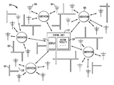
- FIG. 1 shows a transmission detection, identification, and reporting system.
- FIG. 2 illustrates a system for detecting a transmission facility
- FIG. 3 illustrates antenna configurations
- FIG. 4 illustrates a system for detecting a transmission facility in a cell environment.
- FIG. 5 shows a system for detecting a transmission facility in a cell environment.
- FIG. 6 illustrates a block diagram relating to actions taken when detecting transmission facilities.
- FIG. 7 shows a transmission facility detection system wherein an antenna array is used to calculate location.
- FIG. 8 shows a transmission facility detection system wherein a signal source is differentiated between two adjacent rooms.
- FIG. 9 illustrates a transmission facility detection system wherein multiple antennas are used to identify the location of a signal source after an omni-directional antenna has detected its presence.
- FIG. 10 shows a schematic diagram of a system for detecting signals of a transmission facility.
- FIG. 11 shows a schematic diagram of an alternate embodiment of a system for detecting a signal of a transmission facility.
- FIG. 12 shows a schematic diagram of a main circuit board within a system for detecting transmission facilities.
- FIG. 13 shows a schematic diagram of a sub-station in a system for detecting transmission facilities.
- FIG. 14 illustrates a null detection facility
- the transmission detection, identification, and reporting system 100 described herein provides a method of detecting a transmission facility 202 , such as depicted in FIG. 2 , within an environment rich in obstructions 102 .
- One embodiment of the transmission detection, identification, and reporting system 100 may involve the detection of a mobile phone within a heavily walled and metal-barred government facility such as a correctional facility.
- the system may utilize an array of antennas 104 selectively placed within the facility, collection substations 108 for localized collection of detected signals, a central unit 110 for the processing of incoming signals from the facility, a display 112 for showing the location of the detected transmission facility 202 , and an action facility 114 for implementing standard procedures in the event of a detection.
- the communications between the antennas 104 and the substations 108 , and between the substations 108 and the central unit 110 may be wireless to make installation and maintenance of the system within the facility, cost and time effective.
- Selective placement of the antennas 104 combined with algorithms and methods for determining location of the transmission facility 202 , may allow a substantially improved means for locating transmission facilities 202 , such as mobile phones, in an otherwise heavily shielded environment.
- the antenna 104 may be a multi-dipole embedded antenna. Two examples of dual dipole embedded antennas are provided in FIG. 3 as a first dual-dipole embedded antenna 302 and a second dual dipole embedded antenna 304 . In embodiments the antenna may be adapted to receive one, two, three, four, or more bandwidths. In embodiments the antenna 104 may be a dipole antenna 104 , a Yagi-Uda antenna 104 , a loop antenna 104 , a quad antenna 104 , a micro-strip antenna 104 , a quad antenna 104 , a helical antenna 104 , a phase array antenna 104 , a patch antenna or the like.
- the transmission facility 202 may be a mobile phone, such as a flip phone, a slide phone, a cellular phone, a handset, a satellite phone, a 3G phone, a wireless phone, a cordless phone or the like.
- the transmission facility 202 may be a radio, such as a walkie-talkie, a mobile radio, a short-wave radio, or the like.
- the transmission band from the transmission may be within the radio or other electromagnetic frequency spectrum, such as extremely low frequency (ELF), super low frequency (SLF), ultra low frequency (ULF), very low frequency (VLF), low frequency (LF), medium frequency (MF), high frequency (HF), very high frequency (VHF), ultra high frequency (UHF), super high frequency (SHF), extremely high frequency (EHF), microwave, a frequency suitable for 802.11x wireless communications, ultra wide band (UWB), Bluetooth, or the like.
- EHF extremely low frequency
- SLF super low frequency
- ULF very low frequency
- VLF very low frequency
- LF low frequency
- MF medium frequency
- HF high frequency
- VHF very high frequency
- UHF ultra high frequency
- SHF super high frequency
- EHF extremely high frequency
- microwave a frequency suitable for 802.11x wireless communications
- UWB ultra wide band
- Bluetooth or the like.
- the obstruction 102 rich environment may be a building, such as a corrections facility, a school, a government facility, a store, a mall, a residence, a hotel, a motel, or the like.
- the obstruction 102 rich environment may be a large confined space, such as a courtyard, a food court, a recess area, a hallway, greenhouse, recreation room, gymnasium, auditorium, kitchen, cafeteria, craft area, work area, library, prison yard, or the like.
- the obstruction 102 may be a transmission, device transmission obstruction 102 , such as cinderblock, cement, rebar, wire cage, metal, metal coated surface, or the like.
- the obstruction 102 may be other construction materials, such as wood, glass, rug, flooring materials, roofing materials, and the like.
- the transmitting signal information from the antenna 104 module to the central unit 110 may be through a communications connection, such as an IEEE 802.15.4 wireless network, IEEE 802.11 Wi-Fi, Bluetooth, Ethernet, or the and the like.
- the communications connection may utilize CAT-5, RJ-45, RS-232 connections, and the like.
- the communications connection may utilize an optical connection, such as a wireless infrared link, an optical fiber, and the like.
- the transmitting signal information from the antenna 104 module to the central unit 110 may contain data, such as CDMA, CDPD, GSM, TDMA, and the like, and may be used to discriminate which service signal is being used, such as Verizon, Cingular, T-Mobile, Sprint, and the like.
- the detection of the cell phones may be resolved down to cell phone manufacturer and cell phone provider.
- the transmitting signal information to the central unit 110 may be made through an intermediate connection, such as a substation 108 , router, switch, hub, bridge, multiplexer, modem, network card, network interface, processing unit, preprocessor, computer, repeater, antenna 104 , and the like.
- an intermediate connection such as a substation 108 , router, switch, hub, bridge, multiplexer, modem, network card, network interface, processing unit, preprocessor, computer, repeater, antenna 104 , and the like.
- the central unit 110 may have in part a computer, a computer system, a network of computers, a state machine, a sequencer, a microprocessor, a digital signal processor, an audio processor, a preprocessor, a microprocessor, and the like.
- the central unit 110 may process information, such as location information, such as the location of people, inmates, corrections personnel, visitors, all personnel within the facility, equipment, resources, weapons, products, incoming goods, outgoing goods, and the like.
- the information may be type of signal, such as mobile phone standard protocols such as CDMA, CDPA, GSM, TDMA, and the like.
- the information may be an event notification, such as personnel under duress, an emergency medical condition, a call for assistance, a fire, a call for police, a theft, and the like.
- the processed information may allow for the tracking of the person or object in possession of the transmission facility 202 , such as a mobile phone, a radio, a weapon, a product, a resource, and the like.
- the processed information may allow for the discrimination and/or association between people or objects, such as determining the ownership of the transmission facility 202 , the assignment of the source of transmission, current location of a transmission facility 202 compared to its predicted location, and the like.
- the processed information may also have time codes and unique identifiers assigned.
- the central unit 110 may have a display 112 , such as a cathode ray tube (CRT), liquid crystal display 112 (LCD), electronic paper, 3D display 112 , head-mounted display 112 , projector, segmented display 112 , computer display 112 , graphic output display 112 , and the like.
- the central unit 110 may have an action facility 114 , comprising a user interface for causing actions relating to the detected transmission facility 202 , such as closing a door, sealing a room, deploying and action signal, initiating an alarm, and the like.
- a central unit 110 as described herein may be replaced by an alternate configuration, such as a configuration of multiple computers, such as a group of servers, processors, or the like, operating in parallel.
- the methods and systems described herein may involve locating computing capabilities in alternative network configurations, such as in a mesh network or a peer-to-peer network.
- the location of a transmission facility 202 may be determined by various radiolocation or signal measurement techniques, including measuring phase, amplitude, time, or a combination of these; or by identifying and locating an area associated with an antenna 104 with the highest signal strength. In embodiments, the location of a transmission facility 202 may be determined when the transmission facility 202 is powered off though detection of a null in the band pass of a transmitted frequency sweep due to the presence of a mobile phone antenna.
- a method of detecting a transmission facility 202 when the transmission facility 202 is not powered may require a transmitting device and a receiving device that can recognize the signature of an antenna 104 associated with the transmission facility 202 .
- the pattern or ‘signature’ of that antenna 104 can be characterized. In embodiments, this characterization may be evaluated with a microprocessor 1402 with results output to a display 112 .
- a database of these signatures can be placed into the device, and as the transmiatter sweeps across the various cell frequencies, a pattern received can be matched against the database patterns to determine the presence of transmission facilities 202 .
- any class of antenna e.g. WI-FI, Blackberry, Walkie-Talkie, etc.
- WI-FI Wireless Fidelity
- the range of a hand held device that can detect an inactive transmission facility is approximately 10 feet. In embodiments, greater distances could be attained for stationary units by increasing the power.
- Radiolocation also referred to as radio-determination, as used herein encompasses any process of finding the location of a transmitter by means of the propagation properties of waves.
- the angle at which a signal is received, as well as the time it takes to propagate, may both contribute to the determination of the location of the transmission facility 202 .
- Methods include (i) a cell-sector system that collects information pertaining to cell and sector ID's, (ii) the assisted-global positioning satellite (GPS) technology utilizing a GPS chipset in a mobile communication facility, (iii) standard GPS technology, (iv) enhanced-observed time difference technology utilizing software residing on a server that uses signal transmission of time differences received by geographically dispersed radio receivers to pinpoint a user's location, (v) time difference of arrival, (vi) time of arrival, (vii) angle of arrival, (viii) triangulation of cellular signals, (iix) location based on proximity to known locations (including locations of other radio-transmitters), (ix) map-based location, or any combination of any of the foregoing, as well as other location facilities known to those of skill in the art.
- GPS assisted-global positioning satellite
- standard GPS GPS technology
- enhanced-observed time difference technology utilizing software residing on a server that uses signal transmission of time differences received by geographically dispersed
- Obstructions 102 to radio wave propagation may greatly reduce the effectiveness of many of the conventional radiolocation methods due to obstruction of the line-of-sight between the transmission facilities 202 and the receiving antennas 104 .
- several of these methods may be effectively used in the location of the transmission facility 202 .
- These methods include time difference of arrival, time of arrival, and angle of arrival, amplitude comparison, and the like.
- the time difference of arrival method determines the difference in the time, or the difference in phase, of the same radio-transmitting signal arriving at different receiving antennas 104 .
- the time of arrival method determines the absolute time of reception of the signal at different receiving antennas 104 , and again, along with the known propagation speed of the radio wave, allows the determination of the location of the transmission facility 202 .
- the angle of arrival method utilizes direction of transmission to different antennas 104 to determine the location of the transmission facility.
- Amplitude comparison method compares the strength of the signal detected at each antenna to determine the location of a transmission facility 202 . For example, two antennas 104 located in the same room would detect different signal amplitudes for the same transmission facility 202 output, thereby providing a means of determining which antenna 104 the transmission facility 202 is closer to.
- Increasing the number of antennas 104 therefore increases the resolution with which the location of the transmission facility 202 may be determined. All of these methods, and combinations of these methods, may employ mathematical processes such as triangulation, trilateration, multilateration, or like, in determining the location of the transmission facility.
- Triangulation is the process of finding coordinates and distance to a point by calculating the length of one side of a triangle, given measurements of angles and/or sides of the triangle formed by that point, such as the target transmission facility 202 , and two other known reference points, such as the receiving antennas 104 . The calculation of the location of the transmission facility 202 may then be performed utilizing the law of sines from trigonometry.
- Tri-lateration is a method similar to triangulation, but unlike triangulation, which uses angle measurements, together with at least one known distance, to calculate the subject's location, tri-lateration uses the known locations of two or more reference points and the measured distance to the subject, such as the transmission facility 202 , and each reference point, such as the receiving antennas 104 .
- Multi-lateration, or hyperbolic positioning is similar to tri-lateration, but multi-lateration uses measurements of time difference of arrival, rather than time of arrival, to estimate location using the intersection of hyperboloids.
- the location of a single antenna may be known and the single antenna may detect a transmitting device.
- the location of the transmitting device may be estimated through its known proximity to the single antenna location. This may provide adequate location resolution for certain applications of the technology.
- two or more antennas may be used and each of the antenna locations may be known. When each of the antennas receives a transmission, the corresponding signal strengths may be compared. The one with the highest signal strength may be determined as the one closest to the transmitting device so the corresponding antenna location may provide enough location resolution for certain applications.
- a corrections facility presents an ideal example of how the transmission detection, identification, and reporting system 100 may significantly increase the detection of transmission facilities 202 such as mobile phones, a significant challenge to authorities of the correction facilities.
- the system maybe placed throughout the corrections facility for the purpose of alerting the corrections staff that cell phone activity is taking place, the location of the activity and the type, i.e., Nextel, T-Mobile, Verizon, and the like.
- the following technology may also allow for a standalone detection unit 408 or set of detection units 408 to detect cell phones in schools, buildings and other environments in which the facility's or area's provider does not wish the use of cell phones and is interested in the detection of cell phone use.
- the system may include an integrated antenna 104 and RF detector (together referred to as a detector unit 408 ), a substation 108 , whose purpose may be to communicate with each detector unit 408 within its sector, and report activity to the central unit 110 which reports confirmed activity, type of cell phone, and location to the display 112 of the central unit 110 .
- detection units 408 may be used individually or in conjunction with each other and may triangulate detection within a specific area.
- detection units 408 within these basic groups of detection units 408 may be various detection unit 408 types. Some detection unit 408 s may be designed to be hard wired via RJ-45 connectors and CAT 5e cable, other detection units 408 may use 802.11b (WI-FI) wireless communications between detection units 408 , and there may also be an Infra Red (IR) set of detection units 408 which utilize optical communications techniques. Each communications type may have a specific purpose within the corrections facility or other type of building and/or areas. Hard-wired units may be used when it is not possible to use either an optical unit or a WI-FL unit. Used when there are walls embedded with metal or where the distance and the obstructions 102 may preclude a wireless technique.
- WI-FI 802.11b
- IR Infra Red
- WI-FL detection units 408 be used when it is effective to communicate in an area where there are obstructions 102 such as cement walls or cement with embedded rebar walls, facades, and the like. Optical detection units 408 may be used in areas where clear, line-of-site communications may be possible. Optical detection units 408 may operate over relatively long distances, such as 3,000 feet, while WI-FI detection units 408 may be limited to shorter distances, such as 250 feet.
- a hand-held detection units 408 may also be used once a cell phone has been detected, and the corrections officer(s) or monitor are attempting to pinpoint the location.
- This detection unit 408 may be similar to the integrated antenna/detector unit of the main system.
- This detector unit 408 may output an audible alarm whose pitch changes as the signal becomes stronger or weaker.
- a second type of hand-held detector unit 408 may be used to detect a cell phone when it is either off or in a standby condition, also referred to as null detecting.
- Null detection may be used at an ingress or egress of a building or area as a way of detecting a communication device or device with an antenna. This technique may be used in areas where it is unpractical, unwanted or unwarranted to have x-ray machines or more intrusive detection systems.
- a null detection system may also be deployed in a handheld device so an inspector can move through an area attempting to detect a communication device. In embodiments, the null detection system may detect the presence of a transmission facility even when the transmission facility is not transmitting a signal.
- a hand held or mounted null detection device may be used in a correctional institution or other government facility.
- null detection may utilize a transmission-detection source, independent of the transmission source being detected, which is capable of sweeping across the frequency spectrum of interest and receiving it's returning signal.
- the transmission source sweeps the spectrum of interest, searching for distortions in the returned field. Distortions in the spectrum may be due to the presence of an antenna of a transmission facility 202 .
- Matching the distortion, also referred to as a null in the band pass, to characteristics of known antennas used with mobile phones may allow the detection and/or identification of the transmission facility 202 .
- the unit may output an audible “beep” if it detects a null, allowing the officers to focus in on the location of the cell phone.
- the range of the hand-held detection units 408 may be, for example, 15 to 20 feet. This will allow cell phones that are in the immediate vicinity to be quickly detected.
- the null detection may be applicable for egress detection.
- a survey may be performed to determine optimal placement and the type and number of detection units 408 required. This will insure the minimum number of required detection units 408 to perform optimal detection.
- the team may provide a report detailing the layout determined to be optimized for the facility and may review this report with the facilities staff so that any required modifications to the plan may be incorporated before installation is begun.
- the initial coverage of a facility may be in the cell blocks 402 and/or pod areas.
- the same may be true for linear facilities.
- the survey may cover the entire facility, including open areas, such as courtyards, where required. But the most likely place for the initial install may be in the prison cellblocks 402 , since that is where the highest probability of detection may take place.
- the cell block units may be mounted inside each chase 404 (a column positioned between cells in a cell block that includes various utility facilities, such as for plumbing and electricity), as shown in FIG. 4 , and may communicate to a substation 108 located at one end of the block.
- This detection unit 408 may communicate its information to the central unit 110 so that tracking, confirmation, and display may be accomplished.
- detector units 408 may be mounted along the walls 102 , as shown in FIG. 5 , opposite the cells 402 and perform their function similar to the detection units 408 mounted within a chase 404 .
- detector units 408 may be installed in open areas such as gymnasiums, kitchens, cafeterias, craft and work areas and other open areas where a cell phone may be used.
- the difference in these locations from the cell blocks 402 may include the method of detection and tracking. Since most facilities may only require the identification of a cell phones presence within a room, and there could be many inmates within that room, the process may be to lock-down the room, or rooms, in that area and use a hand held device and a physical search to pinpoint the phone location.
- a generalized block diagram is shown in FIG. 6 . For those facilities that require resolving the location within a large interior room or area, the use of triangulation to resolve to a 10.times.10 foot area may be used.
- facilities with the requirement to detect cell phones 202 in outside yard areas the use of triangulation to a 25.times.25 foot space or smaller foot space may be constructed.
- the system may track its movement. Each square foot sector may overlap an adjoining sector. In this way, as shown in FIG. 7 , tracking may be continuous, without any gaps.
- the number and placement of antennas 104 may be critical. In order to sector large regions, such as a ten-by-ten ft section, within the room, the antenna 104 may need to be capable of narrowing their window to an area small enough to meet the requirement.
- FIG. 9 there is an omni-directional antenna 104 , which detects signal presence. Once a signal crosses a threshold, the direction finding antennas 104 may be turned on to determine the position of the signal. This may be reported to the display 112 and tracked until it is either turned off or moves to another room or hallway. Then, normal positional tracking may take place.
- the transmission detection, identification, and reporting system 100 may work in conjunction with a personal alarm system.
- This dual role system may allow for more cost effective use of the detection units 408 and provide for greater protection for the correctional officer.
- This detection system may utilize an individualized frequency, with known frequency separation between detection units 408 .
- the detection configuration of the detection units 408 may provide complete coverage of the facility. Each unit may be continually tracked throughout the facility. At all ingress or egress points the focus of the detection may ensure accurate location of all correctional personnel. With the combined systems more detection units 408 may be need to ensure full coverage.
- the transmission detection, identification, and reporting system 100 may allow for cell phone owner discrimination.
- the system may provide for the allowance of authorized cell phones within the prohibited area.
- the system may detect and identify each cell phone and compare the cell phone identity to the allowed cell phone user list.
- the system may record all phone use and may automatically alert the facility of all prohibited cell phone use.
- each cell phone detection event may be identified with a unique identifier and time code, to ensure proper identification.
- the cell scan- 1 detection system 1000 is an embodiment of a system for detecting signals of a transmission facility.
- An antenna 104 receives transmission signals from wireless transmission device (not shown).
- Antenna 104 may operate, for example in the range of 2.4 GHz with a bandwidth of 465 MHz.
- the received signals are then provided to a microprocessor to determine if the transmission facility for example is a person with a transmission facility (wristband) and may allow or prevent them from accessing an area, it may also alert the central unit of their entering or desire to enter a restricted area.
- the transmission facility for example were a cell phone and the cell phone was in use within a restricted area
- the cell phone would be identified by the central unit as being in a restricted area, then the system will determine whether the cell phone authorized or not authorized, then the system would make a determination, based upon set rules whether to allow or disallow the transmission unit.
- the cell scan- 2 detection system 1100 shown in FIG. 11 , shows an alternate embodiment of a system for detecting a signal of a transmission facility.
- the RF filters i.e., band pass filter
- isolate sets of frequencies for greater sensitivity in this example a low band cell phone signals and high band cell phone signals.
- the operation of the elements in FIG. 11 is similar to that of FIG. 10 and need not be discussed in detail herein.
- the main board system 1200 is an embodiment of a main circuit board within a system for detecting transmission facilities.
- the system may be used to determine each signal received is an actual cell phone signal and not a spurious output, a test may need to be performed that checks for the ‘persistence’ of the received signal.
- a persistence test may run a timer 1202 for a minimum required time that may be nearly as long as the time of the shortest signal type expected. If the signal is present at the end of the timeout period, it is less likely to be a spurious response and more likely that it is a cell phone output. For example, if a GSM signal of 500 microseconds long is the shortest duration signal of all the cell phone protocols received, the persistence test may run for 450 microseconds to further ensure that the received signal is not merely a spurious response.
- the sub-station system 1300 shown in FIG. 13 , is an embodiment of a sub-station in a system for detecting transmission facilities.
- FIG. 14 illustrates an embodiment of a null detector ( 1400 ), wherein the VCO in FIG. 14 tunes to known antenna frequencies and the system detects a null in the known antenna frequencies in which the antenna is detected.
- the null detection system may detect the presence of a transmission facility even when the transmission facility is not transmitting a signal.
- a hand held or mounted null detection device may be used in a correctional institution or other government facility.
- null detection may utilize a transmission-detection source, independent of the transmission source being detected, which is capable of sweeping across the frequency spectrum of interest and receiving it's returning signal. The transmission source sweeps the spectrum of interest, searching for distortions in the returned field. Distortions in the spectrum may be due to the presence of an antenna of a transmission facility 202 .
- detection levels may be determined by which output levels are possible with the various cell phone technologies that are in use today. Since the system described is an amplitude system, the strongest and weakest possible signals must be determined in order to identify the system's required dynamic range. Cell phone signals vary from ⁇ 22 dBW to 6 DBW and this range defines the detection requirements of the system. This translates to a maximum signal of 4.0 Watts at the antenna. The minimum value is equal to 0.006 Watts or 6 milliwatts. Therefore, the dynamic range required is ⁇ 52 dBm to +36 dBm. In order to achieve such a dynamic range, an amplifier that is gain adjustable is required such that an input value of +36 dBm, the amplifier is not saturated.
- the system determines the characteristics required to insure that each cell phone is correctly identified.
- the amplitude of each signal is determined which allows the system to determine which sensor has received the largest signal.
- the system time stamps each data sample so that other sensors receiving the same signal will be recognized as such when the data is presented for analysis.
- Each sensor analyzes the wave shape of the signal detected.
- Each transmission type i.e., CDMA2000, PCS, TDMA, GSM, IS-95, etc.
- Each wave shapes allow the analysis software to recognize that signals seen in different parts of a facility can be associated with each other (using time and wave shape) and the signal that consistently contains the largest amplitude will be identified as closest to the cell phone transmission
- signals directed toward an IED may be intercepted, identified and denied service. Such interception may be up to a known range in forward and side quadrants.
- the identification and determination of the position of the person or persons using a satellite phone and/or land-based cell phone may be determined.
- Cell phones, as well as other RF devices, e.g., garage door openers, walkie-talkie, etc. may be captured, identified and/or jammed that are attempting to activate or contact the IED.
- the cell phone when a cell phone, for example, is on, but not in an active communication, the cell phone is essentially invisible to anyone attempting to monitor cell phone activity.
- the system described herein operates as a cell tower. That is, the system actively addresses the problem of cell phone detection by operating (becoming) the tower.
- a vehicle with similar (but modified equipment to that of a cell tower may actively poll the area of phones that are “on but not in a communication of any sort.”
- the vehicle i.e., Pseudo Tower
- the Pseudo Tower would affect a handoff and make itself the active tower.
- the captured cell phones are not allowed to rotate back to (i.e., connect to) the local cell phone tower, insuring that any calls attempting to communicate with the detonation cell phone will not be sent.
- a call history of each suspect cell phone may be analyzed.
- the caller's presence can be identified. Furthermore, the call being made is not forwarded to the detonation cell phone and the IED will not be activated.
- the direction of the caller is then known. Direction identification is performed by using a technique such an interferometry. In this case, multiple antennas employing interferometry may be used to scan through the current cell phone traffic identifying first, candidate threats and then, pinpointing high probability locations which can be viewed through a high powered binoculars to determine whether the candidate is in need of investigation. Criteria for determining which cell locations may be threats is a pole or road sign, etc.
- the Psuedo Tower may continue controlling all of the phones in the area, preventing any forwarding of calls until all possible threats have been cleared. At this point, the personnel have the option of going after the caller or deactivating the IED, or both. It would be possible to clear the area and detonate the device later if that is a desired plan of action.
- the Pseudo Tower may also be designed to deny service to any active and inactive phone within a given geographical area and pinpoint the location of said phones.
- Satellite cell phone transmission presents a somewhat different problem. Since the transmission from phone to satellite to phone is communicated to a number of satellites, becoming a replacement for the satellite will require cooperation from the provider. Via one or more specific codes, the satellites may be told that the vehicle mounted satellite simulator (i.e., Pseudo Tower) will be taking over the control of phones within a certain radius. Since this is a moving or ever changing circle, the replacement “satellite” will have to continuously update the actual satellite of its position and which phones are being released and which phones are being controlled. Once this function has been implemented, the control of the suspect phones is similar to that of the cell phone. Determining the caller's position and the location of the detonation phone is as above.
- the vehicle mounted satellite simulator i.e., Pseudo Tower
Abstract
Description
- This application claims the benefit of the earlier filing date, pursuant to 35 USC 120, as a Divisional application to that patent application entitled “Systems and Methods for Detection of Transmission Facilities,” filed on Jul. 14, 2006 and afforded Ser. No. 11/457,786 (now U.S. Pat. No. 8,078,190), which claims the benefit of U.S. application Ser. No. 60/699,281 filed on Jul. 14, 2005 and U.S. Provisional App. No. 60/739,877 filed on Nov. 23, 2005. The entire content of these applications is incorporated herein by reference.
- 1. Field
- This invention relates to location of transmission facilities and more particularly to the location of transmission facilities, such as cellular phones, in correctional institutions.
- 2. Background
- There are many facilities, such as government buildings, and in particular correctional facilities, such as prisons, that do not permit cellular phone usage on the premises or even possession of cell phones in the premises. Finding and preventing usage of cell phones and other transmission facilities is difficult, and a need exists for improved methods of locating such devices, as well as a need for detecting such devices upon ingress to a facility.
- Provided herein are methods and systems for locating transmission facilities such as cell phones, mobile phones, satellite phones, radios, transmitters, PDAs, beepers, pagers, walkie-talkies, email devices, instant messenger devices, voice over IP devices, and other types of wireless communication or transmission facilities.
- Embodiments relate to locating and managing the use and presence of wireless communication facilities. Embodiments relate to detecting such devices when they transmit a signal. Other embodiments relate to detecting non-active transmission facilities.
- In certain embodiments the methods and systems disclosed herein include methods and systems for detecting a transmitting device within an obstruction rich environment. The methods and systems may include detecting the transmitting device with a wireless transmission detection facility; communicating signal information relating to the detected transmitting device from the wireless transmission detection facility to a central unit; determining the location of the transmitting device; displaying information of the detection and location of the transmitting device through a user interface; and providing an action facility for causing actions related to the detected transmitting device. In embodiments, the wireless transmission detection facility is an antenna. In embodiments, the antenna is a dual dipole embedded antenna. In embodiments, the dual dipole embedded antenna is tuned to receive cell phone transmissions. In embodiments the dual dipole embedded antenna is tuned to receive a frequency band of approximately 700 to 950 MHz. In embodiments the dual dipole embedded antenna is tuned to receive a frequency band of approximately 1.7 to 2.0 GHz. In embodiments the dual dipole antenna is tuned to receive signals in frequency bands of approximately 700 to 950 MHz and 1.7 to 2.0 GHz. In embodiments the obstruction rich environment is a correctional facility. In embodiments the obstruction rich environment is a mall. In embodiments communicating the information relating to the detected transmitting device from the wireless transmission detection facility to a central unit involves wireless communications. In embodiments the wireless communications are 802.11 communications. In embodiments determining the location of the transmitting device is accomplished through transmission triangulation. In embodiments location of the transmitting device is accomplished through a known location of a single antenna.
- The systems and methods described herein may be understood by reference to the following figures:
-
FIG. 1 shows a transmission detection, identification, and reporting system. -
FIG. 2 illustrates a system for detecting a transmission facility -
FIG. 3 illustrates antenna configurations. -
FIG. 4 illustrates a system for detecting a transmission facility in a cell environment. -
FIG. 5 shows a system for detecting a transmission facility in a cell environment. -
FIG. 6 illustrates a block diagram relating to actions taken when detecting transmission facilities. -
FIG. 7 shows a transmission facility detection system wherein an antenna array is used to calculate location. -
FIG. 8 shows a transmission facility detection system wherein a signal source is differentiated between two adjacent rooms. -
FIG. 9 illustrates a transmission facility detection system wherein multiple antennas are used to identify the location of a signal source after an omni-directional antenna has detected its presence. -
FIG. 10 shows a schematic diagram of a system for detecting signals of a transmission facility. -
FIG. 11 shows a schematic diagram of an alternate embodiment of a system for detecting a signal of a transmission facility. -
FIG. 12 shows a schematic diagram of a main circuit board within a system for detecting transmission facilities. -
FIG. 13 shows a schematic diagram of a sub-station in a system for detecting transmission facilities. -
FIG. 14 illustrates a null detection facility. - Detection of a transmission facility, such as a mobile phone or hand-held radio transmitter, or other transmission facility as described herein, within an obstruction rich environment, such as a facility with many physical barriers to electronic transmission, is difficult to achieve. Referring to
FIG. 1 , the transmission detection, identification, andreporting system 100 described herein provides a method of detecting atransmission facility 202, such as depicted inFIG. 2 , within an environment rich inobstructions 102. One embodiment of the transmission detection, identification, andreporting system 100 may involve the detection of a mobile phone within a heavily walled and metal-barred government facility such as a correctional facility. In this embodiment, the system may utilize an array ofantennas 104 selectively placed within the facility,collection substations 108 for localized collection of detected signals, acentral unit 110 for the processing of incoming signals from the facility, adisplay 112 for showing the location of the detectedtransmission facility 202, and anaction facility 114 for implementing standard procedures in the event of a detection. In this embodiment, the communications between theantennas 104 and thesubstations 108, and between thesubstations 108 and thecentral unit 110, may be wireless to make installation and maintenance of the system within the facility, cost and time effective. Selective placement of theantennas 104, combined with algorithms and methods for determining location of thetransmission facility 202, may allow a substantially improved means for locatingtransmission facilities 202, such as mobile phones, in an otherwise heavily shielded environment. - In embodiments the
antenna 104 may be a multi-dipole embedded antenna. Two examples of dual dipole embedded antennas are provided inFIG. 3 as a first dual-dipole embeddedantenna 302 and a second dual dipole embeddedantenna 304. In embodiments the antenna may be adapted to receive one, two, three, four, or more bandwidths. In embodiments theantenna 104 may be adipole antenna 104, a Yagi-Udaantenna 104, aloop antenna 104, aquad antenna 104, amicro-strip antenna 104, aquad antenna 104, ahelical antenna 104, aphase array antenna 104, a patch antenna or the like. - In embodiments, the
transmission facility 202 may be a mobile phone, such as a flip phone, a slide phone, a cellular phone, a handset, a satellite phone, a 3G phone, a wireless phone, a cordless phone or the like. In embodiments, thetransmission facility 202 may be a radio, such as a walkie-talkie, a mobile radio, a short-wave radio, or the like. - In embodiments, the transmission band from the transmission may be within the radio or other electromagnetic frequency spectrum, such as extremely low frequency (ELF), super low frequency (SLF), ultra low frequency (ULF), very low frequency (VLF), low frequency (LF), medium frequency (MF), high frequency (HF), very high frequency (VHF), ultra high frequency (UHF), super high frequency (SHF), extremely high frequency (EHF), microwave, a frequency suitable for 802.11x wireless communications, ultra wide band (UWB), Bluetooth, or the like.
- In embodiments, the
obstruction 102 rich environment may be a building, such as a corrections facility, a school, a government facility, a store, a mall, a residence, a hotel, a motel, or the like. In embodiments, theobstruction 102 rich environment may be a large confined space, such as a courtyard, a food court, a recess area, a hallway, greenhouse, recreation room, gymnasium, auditorium, kitchen, cafeteria, craft area, work area, library, prison yard, or the like. In embodiments, theobstruction 102 may be a transmission,device transmission obstruction 102, such as cinderblock, cement, rebar, wire cage, metal, metal coated surface, or the like. In embodiments, theobstruction 102 may be other construction materials, such as wood, glass, rug, flooring materials, roofing materials, and the like. - In embodiments, the transmitting signal information from the
antenna 104 module to thecentral unit 110 may be through a communications connection, such as an IEEE 802.15.4 wireless network, IEEE 802.11 Wi-Fi, Bluetooth, Ethernet, or the and the like. In embodiments, the communications connection may utilize CAT-5, RJ-45, RS-232 connections, and the like. In embodiments the communications connection may utilize an optical connection, such as a wireless infrared link, an optical fiber, and the like. - In embodiments, the transmitting signal information from the
antenna 104 module to thecentral unit 110 may contain data, such as CDMA, CDPD, GSM, TDMA, and the like, and may be used to discriminate which service signal is being used, such as Verizon, Cingular, T-Mobile, Sprint, and the like. The detection of the cell phones may be resolved down to cell phone manufacturer and cell phone provider. - In embodiments, the transmitting signal information to the
central unit 110 may be made through an intermediate connection, such as asubstation 108, router, switch, hub, bridge, multiplexer, modem, network card, network interface, processing unit, preprocessor, computer, repeater,antenna 104, and the like. - In embodiments, the
central unit 110 may have in part a computer, a computer system, a network of computers, a state machine, a sequencer, a microprocessor, a digital signal processor, an audio processor, a preprocessor, a microprocessor, and the like. - In embodiments, the
central unit 110 may process information, such as location information, such as the location of people, inmates, corrections personnel, visitors, all personnel within the facility, equipment, resources, weapons, products, incoming goods, outgoing goods, and the like. In embodiments, the information may be type of signal, such as mobile phone standard protocols such as CDMA, CDPA, GSM, TDMA, and the like. In embodiments, the information may be an event notification, such as personnel under duress, an emergency medical condition, a call for assistance, a fire, a call for police, a theft, and the like. In embodiments, the processed information may allow for the tracking of the person or object in possession of thetransmission facility 202, such as a mobile phone, a radio, a weapon, a product, a resource, and the like. In embodiments, the processed information may allow for the discrimination and/or association between people or objects, such as determining the ownership of thetransmission facility 202, the assignment of the source of transmission, current location of atransmission facility 202 compared to its predicted location, and the like. In embodiments, the processed information may also have time codes and unique identifiers assigned. - In embodiments, the
central unit 110 may have adisplay 112, such as a cathode ray tube (CRT), liquid crystal display 112 (LCD), electronic paper,3D display 112, head-mounteddisplay 112, projector, segmenteddisplay 112,computer display 112,graphic output display 112, and the like. In embodiments, thecentral unit 110 may have anaction facility 114, comprising a user interface for causing actions relating to the detectedtransmission facility 202, such as closing a door, sealing a room, deploying and action signal, initiating an alarm, and the like. - In embodiments the functions of a
central unit 110 as described herein may be replaced by an alternate configuration, such as a configuration of multiple computers, such as a group of servers, processors, or the like, operating in parallel. In embodiments the methods and systems described herein may involve locating computing capabilities in alternative network configurations, such as in a mesh network or a peer-to-peer network. - In embodiments, the location of a
transmission facility 202 may be determined by various radiolocation or signal measurement techniques, including measuring phase, amplitude, time, or a combination of these; or by identifying and locating an area associated with anantenna 104 with the highest signal strength. In embodiments, the location of atransmission facility 202 may be determined when thetransmission facility 202 is powered off though detection of a null in the band pass of a transmitted frequency sweep due to the presence of a mobile phone antenna. - In embodiments, a method of detecting a transmission facility 202 (e.g. cell phone) when the
transmission facility 202 is not powered may require a transmitting device and a receiving device that can recognize the signature of anantenna 104 associated with thetransmission facility 202. By transmitting a known frequency and receiving the disturbance pattern produced by having aparticular antenna 104 design in the transmission path, the pattern or ‘signature’ of thatantenna 104 can be characterized. In embodiments, this characterization may be evaluated with amicroprocessor 1402 with results output to adisplay 112. A database of these signatures can be placed into the device, and as the transmiatter sweeps across the various cell frequencies, a pattern received can be matched against the database patterns to determine the presence oftransmission facilities 202. In embodiments, any class of antenna (e.g. WI-FI, Blackberry, Walkie-Talkie, etc.) can be classified and identified. - In embodiments, the range of a hand held device that can detect an inactive transmission facility is approximately 10 feet. In embodiments, greater distances could be attained for stationary units by increasing the power.
- Radiolocation, also referred to as radio-determination, as used herein encompasses any process of finding the location of a transmitter by means of the propagation properties of waves. The angle at which a signal is received, as well as the time it takes to propagate, may both contribute to the determination of the location of the
transmission facility 202. There are a variety of methods that may be employed in the determination of the location of atransmission facility 202. Methods include (i) a cell-sector system that collects information pertaining to cell and sector ID's, (ii) the assisted-global positioning satellite (GPS) technology utilizing a GPS chipset in a mobile communication facility, (iii) standard GPS technology, (iv) enhanced-observed time difference technology utilizing software residing on a server that uses signal transmission of time differences received by geographically dispersed radio receivers to pinpoint a user's location, (v) time difference of arrival, (vi) time of arrival, (vii) angle of arrival, (viii) triangulation of cellular signals, (iix) location based on proximity to known locations (including locations of other radio-transmitters), (ix) map-based location, or any combination of any of the foregoing, as well as other location facilities known to those of skill in the art. -
Obstructions 102 to radio wave propagation may greatly reduce the effectiveness of many of the conventional radiolocation methods due to obstruction of the line-of-sight between thetransmission facilities 202 and the receivingantennas 104. However, by employing a large array ofantennas 104, positioned so as to maintain line-of-sight betweenpossible transmission facility 202 locations and the receivingantennas 104, several of these methods may be effectively used in the location of thetransmission facility 202. These methods include time difference of arrival, time of arrival, and angle of arrival, amplitude comparison, and the like. The time difference of arrival method determines the difference in the time, or the difference in phase, of the same radio-transmitting signal arriving atdifferent receiving antennas 104. Together with the known propagation speed of the radio wave, allows the determination of the location of thetransmission facility 202. The time of arrival method determines the absolute time of reception of the signal atdifferent receiving antennas 104, and again, along with the known propagation speed of the radio wave, allows the determination of the location of thetransmission facility 202. The angle of arrival method utilizes direction of transmission todifferent antennas 104 to determine the location of the transmission facility. Amplitude comparison method compares the strength of the signal detected at each antenna to determine the location of atransmission facility 202. For example, twoantennas 104 located in the same room would detect different signal amplitudes for thesame transmission facility 202 output, thereby providing a means of determining whichantenna 104 thetransmission facility 202 is closer to. Increasing the number ofantennas 104 therefore increases the resolution with which the location of thetransmission facility 202 may be determined. All of these methods, and combinations of these methods, may employ mathematical processes such as triangulation, trilateration, multilateration, or like, in determining the location of the transmission facility. - Triangulation is the process of finding coordinates and distance to a point by calculating the length of one side of a triangle, given measurements of angles and/or sides of the triangle formed by that point, such as the
target transmission facility 202, and two other known reference points, such as the receivingantennas 104. The calculation of the location of thetransmission facility 202 may then be performed utilizing the law of sines from trigonometry. Tri-lateration is a method similar to triangulation, but unlike triangulation, which uses angle measurements, together with at least one known distance, to calculate the subject's location, tri-lateration uses the known locations of two or more reference points and the measured distance to the subject, such as thetransmission facility 202, and each reference point, such as the receivingantennas 104. Multi-lateration, or hyperbolic positioning, is similar to tri-lateration, but multi-lateration uses measurements of time difference of arrival, rather than time of arrival, to estimate location using the intersection of hyperboloids. - While several radiolocation and triangulation techniques have been described in connection with locating the transmitting device, it should be understood that one skilled in the art would appreciate that there are other location methodologies and such location methodologies are encompassed by the present invention. For example, in embodiments, the location of a single antenna may be known and the single antenna may detect a transmitting device. The location of the transmitting device may be estimated through its known proximity to the single antenna location. This may provide adequate location resolution for certain applications of the technology. Similarly, two or more antennas may be used and each of the antenna locations may be known. When each of the antennas receives a transmission, the corresponding signal strengths may be compared. The one with the highest signal strength may be determined as the one closest to the transmitting device so the corresponding antenna location may provide enough location resolution for certain applications.
- In an embodiment of the transmission detection, identification, and
reporting system 100, a corrections facility, with its substantial andinherent obstruction 102 rich environment, presents an ideal example of how the transmission detection, identification, andreporting system 100 may significantly increase the detection oftransmission facilities 202 such as mobile phones, a significant challenge to authorities of the correction facilities. In this embodiment, the system maybe placed throughout the corrections facility for the purpose of alerting the corrections staff that cell phone activity is taking place, the location of the activity and the type, i.e., Nextel, T-Mobile, Verizon, and the like. The following technology may also allow for astandalone detection unit 408 or set ofdetection units 408 to detect cell phones in schools, buildings and other environments in which the facility's or area's provider does not wish the use of cell phones and is interested in the detection of cell phone use. - In an embodiment, the system may include an
integrated antenna 104 and RF detector (together referred to as a detector unit 408), asubstation 108, whose purpose may be to communicate with eachdetector unit 408 within its sector, and report activity to thecentral unit 110 which reports confirmed activity, type of cell phone, and location to thedisplay 112 of thecentral unit 110. Thesedetection units 408 may be used individually or in conjunction with each other and may triangulate detection within a specific area. The outside yard areas may be monitored bydetection units 408, which may cover large areas, such as 25.times.25 foot sectors or 5=5 foot sectors, to localize the detection of a cell phone and track its position from one sector to any adjoining sector. That is, as the person moves with a phone, the changing position of that phone may be reported. If the phone moves inside the facility, tracking may continue asinterior detection units 408 detect the phone. - In an embodiment, within these basic groups of
detection units 408 may bevarious detection unit 408 types. Some detection unit 408 s may be designed to be hard wired via RJ-45 connectors and CAT 5e cable,other detection units 408 may use 802.11b (WI-FI) wireless communications betweendetection units 408, and there may also be an Infra Red (IR) set ofdetection units 408 which utilize optical communications techniques. Each communications type may have a specific purpose within the corrections facility or other type of building and/or areas. Hard-wired units may be used when it is not possible to use either an optical unit or a WI-FL unit. Used when there are walls embedded with metal or where the distance and theobstructions 102 may preclude a wireless technique. WI-FL detection units 408 be used when it is effective to communicate in an area where there areobstructions 102 such as cement walls or cement with embedded rebar walls, facades, and the like.Optical detection units 408 may be used in areas where clear, line-of-site communications may be possible.Optical detection units 408 may operate over relatively long distances, such as 3,000 feet, while WI-FI detection units 408 may be limited to shorter distances, such as 250 feet. - In an embodiment, there may also be a hand-held
detection units 408 to be used once a cell phone has been detected, and the corrections officer(s) or monitor are attempting to pinpoint the location. Thisdetection unit 408 may be similar to the integrated antenna/detector unit of the main system. Thisdetector unit 408 may output an audible alarm whose pitch changes as the signal becomes stronger or weaker. - In an embodiment, a second type of hand-held
detector unit 408 may be used to detect a cell phone when it is either off or in a standby condition, also referred to as null detecting. Null detection may be used at an ingress or egress of a building or area as a way of detecting a communication device or device with an antenna. This technique may be used in areas where it is unpractical, unwanted or unwarranted to have x-ray machines or more intrusive detection systems. A null detection system may also be deployed in a handheld device so an inspector can move through an area attempting to detect a communication device. In embodiments, the null detection system may detect the presence of a transmission facility even when the transmission facility is not transmitting a signal. In embodiments, a hand held or mounted null detection device may be used in a correctional institution or other government facility. In embodiments, null detection may utilize a transmission-detection source, independent of the transmission source being detected, which is capable of sweeping across the frequency spectrum of interest and receiving it's returning signal. The transmission source sweeps the spectrum of interest, searching for distortions in the returned field. Distortions in the spectrum may be due to the presence of an antenna of atransmission facility 202. Matching the distortion, also referred to as a null in the band pass, to characteristics of known antennas used with mobile phones may allow the detection and/or identification of thetransmission facility 202. The unit may output an audible “beep” if it detects a null, allowing the officers to focus in on the location of the cell phone. The range of the hand-helddetection units 408 may be, for example, 15 to 20 feet. This will allow cell phones that are in the immediate vicinity to be quickly detected. The null detection may be applicable for egress detection. - In an embodiment, a survey may be performed to determine optimal placement and the type and number of
detection units 408 required. This will insure the minimum number of requireddetection units 408 to perform optimal detection. The team may provide a report detailing the layout determined to be optimized for the facility and may review this report with the facilities staff so that any required modifications to the plan may be incorporated before installation is begun. - In an embodiment, the initial coverage of a facility may be in the cell blocks 402 and/or pod areas. The same may be true for linear facilities. The survey may cover the entire facility, including open areas, such as courtyards, where required. But the most likely place for the initial install may be in the
prison cellblocks 402, since that is where the highest probability of detection may take place. - In an embodiment, the cell block units may be mounted inside each chase 404 (a column positioned between cells in a cell block that includes various utility facilities, such as for plumbing and electricity), as shown in
FIG. 4 , and may communicate to asubstation 108 located at one end of the block. Thisdetection unit 408 may communicate its information to thecentral unit 110 so that tracking, confirmation, and display may be accomplished. Forlinear facilities 500,detector units 408 may be mounted along thewalls 102, as shown inFIG. 5 , opposite thecells 402 and perform their function similar to thedetection units 408 mounted within achase 404. - In an embodiment,
detector units 408 may be installed in open areas such as gymnasiums, kitchens, cafeterias, craft and work areas and other open areas where a cell phone may be used. The difference in these locations from the cell blocks 402 may include the method of detection and tracking. Since most facilities may only require the identification of a cell phones presence within a room, and there could be many inmates within that room, the process may be to lock-down the room, or rooms, in that area and use a hand held device and a physical search to pinpoint the phone location. A generalized block diagram is shown inFIG. 6 . For those facilities that require resolving the location within a large interior room or area, the use of triangulation to resolve to a 10.times.10 foot area may be used. - In an embodiment, facilities with the requirement to detect
cell phones 202 in outside yard areas, the use of triangulation to a 25.times.25 foot space or smaller foot space may be constructed. As aphone 202 is moved from area coverage 702 to area coverage 702, the system may track its movement. Each square foot sector may overlap an adjoining sector. In this way, as shown inFIG. 7 , tracking may be continuous, without any gaps. - In an embodiment, it may also important to know whether a phone is located on one side of an
obstruction 102 or the other, such as doors, walls, and the like. If the wrong room is identified, it may make it more difficult to locate a phone and its user. As shown inFIG. 8 , detection of the correct room may depend upon the level of the signal received. Proper placement of thedetector units 408 may insure that the phone may be identified in the correct location. - In an embodiment, when sectoring a large room such as a gymnasium, the number and placement of
antennas 104 may be critical. In order to sector large regions, such as a ten-by-ten ft section, within the room, theantenna 104 may need to be capable of narrowing their window to an area small enough to meet the requirement. InFIG. 9 , there is an omni-directional antenna 104, which detects signal presence. Once a signal crosses a threshold, thedirection finding antennas 104 may be turned on to determine the position of the signal. This may be reported to thedisplay 112 and tracked until it is either turned off or moves to another room or hallway. Then, normal positional tracking may take place. - In an embodiment, the transmission detection, identification, and
reporting system 100 may work in conjunction with a personal alarm system. This dual role system may allow for more cost effective use of thedetection units 408 and provide for greater protection for the correctional officer. This detection system may utilize an individualized frequency, with known frequency separation betweendetection units 408. The detection configuration of thedetection units 408 may provide complete coverage of the facility. Each unit may be continually tracked throughout the facility. At all ingress or egress points the focus of the detection may ensure accurate location of all correctional personnel. With the combined systemsmore detection units 408 may be need to ensure full coverage. - In an embodiment, the transmission detection, identification, and
reporting system 100 may allow for cell phone owner discrimination. The system may provide for the allowance of authorized cell phones within the prohibited area. The system may detect and identify each cell phone and compare the cell phone identity to the allowed cell phone user list. The system may record all phone use and may automatically alert the facility of all prohibited cell phone use. In addition, each cell phone detection event may be identified with a unique identifier and time code, to ensure proper identification. - The cell scan-1
detection system 1000, shown inFIG. 10 , is an embodiment of a system for detecting signals of a transmission facility. Anantenna 104 receives transmission signals from wireless transmission device (not shown).Antenna 104 may operate, for example in the range of 2.4 GHz with a bandwidth of 465 MHz. The received signals are then provided to a microprocessor to determine if the transmission facility for example is a person with a transmission facility (wristband) and may allow or prevent them from accessing an area, it may also alert the central unit of their entering or desire to enter a restricted area. In an another embodiment, if the transmission facility for example were a cell phone and the cell phone was in use within a restricted area, the cell phone would be identified by the central unit as being in a restricted area, then the system will determine whether the cell phone authorized or not authorized, then the system would make a determination, based upon set rules whether to allow or disallow the transmission unit. - The cell scan-2
detection system 1100, shown inFIG. 11 , shows an alternate embodiment of a system for detecting a signal of a transmission facility. For this embodiment, the RF filters (i.e., band pass filter) isolate sets of frequencies for greater sensitivity, in this example a low band cell phone signals and high band cell phone signals. The operation of the elements inFIG. 11 is similar to that ofFIG. 10 and need not be discussed in detail herein. - The
main board system 1200, shown inFIG. 12 , is an embodiment of a main circuit board within a system for detecting transmission facilities. The system may be used to determine each signal received is an actual cell phone signal and not a spurious output, a test may need to be performed that checks for the ‘persistence’ of the received signal. A persistence test may run atimer 1202 for a minimum required time that may be nearly as long as the time of the shortest signal type expected. If the signal is present at the end of the timeout period, it is less likely to be a spurious response and more likely that it is a cell phone output. For example, if a GSM signal of 500 microseconds long is the shortest duration signal of all the cell phone protocols received, the persistence test may run for 450 microseconds to further ensure that the received signal is not merely a spurious response. - The
sub-station system 1300, shown inFIG. 13 , is an embodiment of a sub-station in a system for detecting transmission facilities. -
FIG. 14 illustrates an embodiment of a null detector (1400), wherein the VCO inFIG. 14 tunes to known antenna frequencies and the system detects a null in the known antenna frequencies in which the antenna is detected. As one skilled in the art would recognize the application and can modify the system for greater application and distances. In embodiments, the null detection system may detect the presence of a transmission facility even when the transmission facility is not transmitting a signal. In embodiments, a hand held or mounted null detection device may be used in a correctional institution or other government facility. In embodiments, null detection may utilize a transmission-detection source, independent of the transmission source being detected, which is capable of sweeping across the frequency spectrum of interest and receiving it's returning signal. The transmission source sweeps the spectrum of interest, searching for distortions in the returned field. Distortions in the spectrum may be due to the presence of an antenna of atransmission facility 202. - In embodiments of the system described herein, detection levels may be determined by which output levels are possible with the various cell phone technologies that are in use today. Since the system described is an amplitude system, the strongest and weakest possible signals must be determined in order to identify the system's required dynamic range. Cell phone signals vary from −22 dBW to 6 DBW and this range defines the detection requirements of the system. This translates to a maximum signal of 4.0 Watts at the antenna. The minimum value is equal to 0.006 Watts or 6 milliwatts. Therefore, the dynamic range required is −52 dBm to +36 dBm. In order to achieve such a dynamic range, an amplifier that is gain adjustable is required such that an input value of +36 dBm, the amplifier is not saturated.
- In the embodiment, the system determines the characteristics required to insure that each cell phone is correctly identified. The amplitude of each signal is determined which allows the system to determine which sensor has received the largest signal. The system time stamps each data sample so that other sensors receiving the same signal will be recognized as such when the data is presented for analysis. Each sensor analyzes the wave shape of the signal detected. Each transmission type (i.e., CDMA2000, PCS, TDMA, GSM, IS-95, etc.) has a unique wave shape. These wave shapes allow the analysis software to recognize that signals seen in different parts of a facility can be associated with each other (using time and wave shape) and the signal that consistently contains the largest amplitude will be identified as closest to the cell phone transmission
- In embodiments of the invention, signals directed toward an IED (improvised explosive device) may be intercepted, identified and denied service. Such interception may be up to a known range in forward and side quadrants. The identification and determination of the position of the person or persons using a satellite phone and/or land-based cell phone may be determined. Cell phones, as well as other RF devices, e.g., garage door openers, walkie-talkie, etc., may be captured, identified and/or jammed that are attempting to activate or contact the IED.
- In embodiments of the invention, when a cell phone, for example, is on, but not in an active communication, the cell phone is essentially invisible to anyone attempting to monitor cell phone activity. In order to be aware of the existence of such “on but not transmitting devices” the system described herein operates as a cell tower. That is, the system actively addresses the problem of cell phone detection by operating (becoming) the tower. A vehicle with similar (but modified equipment to that of a cell tower may actively poll the area of phones that are “on but not in a communication of any sort.” The vehicle (i.e., Pseudo Tower) collects the current database of active phones and those phones in standby from the tower(s) in the area and uses this data base to poll these phones in order to locate them. Once potential phones that could be possible detonation cell phones are identified and located, the Pseudo Tower would affect a handoff and make itself the active tower. Thus, the captured cell phones are not allowed to rotate back to (i.e., connect to) the local cell phone tower, insuring that any calls attempting to communicate with the detonation cell phone will not be sent. As one of the goals is to identify the person who is attempting to contact the detonation cell phone, a call history of each suspect cell phone may be analyzed.
- When a caller attempts to activate an IED, the caller's presence can be identified. Furthermore, the call being made is not forwarded to the detonation cell phone and the IED will not be activated. By determining a peak angle (triangulation) the caller's cell phone/satellite phone signal, the direction of the caller is then known. Direction identification is performed by using a technique such an interferometry. In this case, multiple antennas employing interferometry may be used to scan through the current cell phone traffic identifying first, candidate threats and then, pinpointing high probability locations which can be viewed through a high powered binoculars to determine whether the candidate is in need of investigation. Criteria for determining which cell locations may be threats is a pole or road sign, etc. The Psuedo Tower may continue controlling all of the phones in the area, preventing any forwarding of calls until all possible threats have been cleared. At this point, the personnel have the option of going after the caller or deactivating the IED, or both. It would be possible to clear the area and detonate the device later if that is a desired plan of action.
- Given the varying parameters by which detonation can take place, the Pseudo Tower may also be designed to deny service to any active and inactive phone within a given geographical area and pinpoint the location of said phones.
- Satellite cell phone transmission presents a somewhat different problem. Since the transmission from phone to satellite to phone is communicated to a number of satellites, becoming a replacement for the satellite will require cooperation from the provider. Via one or more specific codes, the satellites may be told that the vehicle mounted satellite simulator (i.e., Pseudo Tower) will be taking over the control of phones within a certain radius. Since this is a moving or ever changing circle, the replacement “satellite” will have to continuously update the actual satellite of its position and which phones are being released and which phones are being controlled. Once this function has been implemented, the control of the suspect phones is similar to that of the cell phone. Determining the caller's position and the location of the detonation phone is as above.
- Documents referenced herein are hereby incorporated in their entirety by reference. While the invention has been described in connection with certain preferred embodiments, other embodiments would be understood by one of ordinary skill in the art and are encompassed herein.
Claims (6)
Priority Applications (3)
| Application Number | Priority Date | Filing Date | Title |
|---|---|---|---|
| US13/300,560 US9241251B2 (en) | 2005-07-14 | 2011-11-19 | Systems and methods for detection of transmission facilities |
| US15/000,173 US9756498B1 (en) | 2005-07-14 | 2016-01-19 | Systems and methods for detection of transmission facilities |
| US15/694,909 US10708752B1 (en) | 2005-07-14 | 2017-09-04 | System and method for detection of transmission facilities |
Applications Claiming Priority (4)
| Application Number | Priority Date | Filing Date | Title |
|---|---|---|---|
| US69928105P | 2005-07-14 | 2005-07-14 | |
| US73987705P | 2005-11-23 | 2005-11-23 | |
| US11/457,786 US8078190B2 (en) | 2005-07-14 | 2006-07-14 | Systems and methods for detection of transmission facilities |
| US13/300,560 US9241251B2 (en) | 2005-07-14 | 2011-11-19 | Systems and methods for detection of transmission facilities |
Related Parent Applications (1)
| Application Number | Title | Priority Date | Filing Date |
|---|---|---|---|
| US11/457,786 Division US8078190B2 (en) | 2005-07-14 | 2006-07-14 | Systems and methods for detection of transmission facilities |
Related Child Applications (1)
| Application Number | Title | Priority Date | Filing Date |
|---|---|---|---|
| US15/000,173 Continuation-In-Part US9756498B1 (en) | 2005-07-14 | 2016-01-19 | Systems and methods for detection of transmission facilities |
Publications (2)
| Publication Number | Publication Date |
|---|---|
| US20120122402A1 true US20120122402A1 (en) | 2012-05-17 |
| US9241251B2 US9241251B2 (en) | 2016-01-19 |
Family
ID=37669377
Family Applications (9)
| Application Number | Title | Priority Date | Filing Date |
|---|---|---|---|
| US11/457,786 Expired - Fee Related US8078190B2 (en) | 2005-07-14 | 2006-07-14 | Systems and methods for detection of transmission facilities |
| US12/510,006 Expired - Fee Related US8996028B2 (en) | 2005-07-14 | 2009-07-27 | Systems and methods for the detection of transmission facilities |
| US12/983,294 Expired - Fee Related US8989766B2 (en) | 2005-07-14 | 2011-01-01 | Systems and methods for the detection of transmission facilities |
| US13/300,560 Expired - Fee Related US9241251B2 (en) | 2005-07-14 | 2011-11-19 | Systems and methods for detection of transmission facilities |
| US13/323,817 Expired - Fee Related US8996029B2 (en) | 2005-07-14 | 2011-12-12 | Systems and methods for the detection of transmission facilities |
| US13/603,477 Active US9609500B2 (en) | 2005-07-14 | 2012-09-05 | Systems and methods for the detection of transmission facilities |
| US15/206,260 Expired - Fee Related US10367599B1 (en) | 2005-07-14 | 2016-07-09 | Systems and methods for controlling wireless communication devices |
| US15/206,531 Active US10645212B1 (en) | 2005-07-14 | 2016-07-11 | Systems and methods for managing access of wireless communication devices |
| US15/407,184 Active US10868632B1 (en) | 2005-07-14 | 2017-01-16 | System and method for the detection of transmission facilities |
Family Applications Before (3)
| Application Number | Title | Priority Date | Filing Date |
|---|---|---|---|
| US11/457,786 Expired - Fee Related US8078190B2 (en) | 2005-07-14 | 2006-07-14 | Systems and methods for detection of transmission facilities |
| US12/510,006 Expired - Fee Related US8996028B2 (en) | 2005-07-14 | 2009-07-27 | Systems and methods for the detection of transmission facilities |
| US12/983,294 Expired - Fee Related US8989766B2 (en) | 2005-07-14 | 2011-01-01 | Systems and methods for the detection of transmission facilities |
Family Applications After (5)
| Application Number | Title | Priority Date | Filing Date |
|---|---|---|---|
| US13/323,817 Expired - Fee Related US8996029B2 (en) | 2005-07-14 | 2011-12-12 | Systems and methods for the detection of transmission facilities |
| US13/603,477 Active US9609500B2 (en) | 2005-07-14 | 2012-09-05 | Systems and methods for the detection of transmission facilities |
| US15/206,260 Expired - Fee Related US10367599B1 (en) | 2005-07-14 | 2016-07-09 | Systems and methods for controlling wireless communication devices |
| US15/206,531 Active US10645212B1 (en) | 2005-07-14 | 2016-07-11 | Systems and methods for managing access of wireless communication devices |
| US15/407,184 Active US10868632B1 (en) | 2005-07-14 | 2017-01-16 | System and method for the detection of transmission facilities |
Country Status (4)
| Country | Link |
|---|---|
| US (9) | US8078190B2 (en) |
| EP (1) | EP1908269A2 (en) |
| CA (1) | CA2615165A1 (en) |
| WO (1) | WO2007011697A2 (en) |
Cited By (2)
| Publication number | Priority date | Publication date | Assignee | Title |
|---|---|---|---|---|
| USD863268S1 (en) | 2018-05-04 | 2019-10-15 | Scott R. Archer | Yagi-uda antenna with triangle loop |
| US11431837B1 (en) * | 2005-07-14 | 2022-08-30 | Binj Laboratories, Inc. | Systems and methods for detecting and controlling transmission devices |
Families Citing this family (53)
| Publication number | Priority date | Publication date | Assignee | Title |
|---|---|---|---|---|
| US7957356B2 (en) | 2002-05-13 | 2011-06-07 | Misomino Chi Acquisitions L.L.C. | Scalable media access control for multi-hop high bandwidth communications |
| US7852796B2 (en) | 2002-05-13 | 2010-12-14 | Xudong Wang | Distributed multichannel wireless communication |
| US8780770B2 (en) | 2002-05-13 | 2014-07-15 | Misonimo Chi Acquisition L.L.C. | Systems and methods for voice and video communication over a wireless network |
| US7941149B2 (en) | 2002-05-13 | 2011-05-10 | Misonimo Chi Acquistion L.L.C. | Multi-hop ultra wide band wireless network communication |
| WO2007011697A2 (en) * | 2005-07-14 | 2007-01-25 | Binj Laboratories, Inc. | Systems and methods of detection transmission facilities |
| US9756498B1 (en) | 2005-07-14 | 2017-09-05 | Binj Laboratories, Inc. | Systems and methods for detection of transmission facilities |
| US8175613B2 (en) * | 2006-08-04 | 2012-05-08 | Misonimo Chi Acquisitions L.L.C. | Systems and methods for determining location of devices within a wireless network |
| US20130150004A1 (en) * | 2006-08-11 | 2013-06-13 | Michael Rosen | Method and apparatus for reducing mobile phone usage while driving |
| US8233880B2 (en) | 2006-08-16 | 2012-07-31 | Global Tel*Link Corporation | Integration of cellular phone detection and reporting into a prison telephone system |
| WO2008070871A2 (en) | 2006-12-07 | 2008-06-12 | Misonimo Chi Acquisition L.L.C. | System and method for timeslot and channel allocation |
| US8558893B1 (en) | 2007-08-03 | 2013-10-15 | Sprint Communications Company L.P. | Head-up security display |
| US8355961B1 (en) | 2007-08-03 | 2013-01-15 | Sprint Communications Company L.P. | Distribution center head-up display |
| US8023886B2 (en) * | 2007-09-28 | 2011-09-20 | Broadcom Corporation | Method and system for repeater with gain control and isolation via polarization |
| US8634767B2 (en) * | 2007-09-30 | 2014-01-21 | Broadcom Corporation | Method and system for utilizing EHF repeaters and/or transceivers for detecting and/or tracking an entity |
| US8055296B1 (en) * | 2007-11-06 | 2011-11-08 | Sprint Communications Company L.P. | Head-up display communication system and method |
| US8264422B1 (en) | 2007-11-08 | 2012-09-11 | Sprint Communications Company L.P. | Safe head-up display of information |
| US7952363B2 (en) * | 2008-04-25 | 2011-05-31 | Comsonics, Inc. | System and method for sorting detection of signal egress from a wired communication system |
| US20100056045A1 (en) * | 2008-09-02 | 2010-03-04 | Cooper Technologies Company | Ultra Low Frequency-Based Radio Transmission System |
| TWI407714B (en) * | 2008-10-09 | 2013-09-01 | Broadcom Corp | Method and system for utilizing ehf repeaters and/or transceivers for detecting and/or tracking an entity |
| US8437741B2 (en) | 2008-12-19 | 2013-05-07 | Tecore | Intelligent network access controller and method |
| US8825011B2 (en) | 2008-12-19 | 2014-09-02 | Tecore, Inc. | Intelligent network access control |
| US8254886B2 (en) * | 2008-12-19 | 2012-08-28 | Tecore, Inc. | Intelligent network access controller and method |
| US9002286B2 (en) * | 2009-03-30 | 2015-04-07 | Massachusetts Institute Of Technology | Method and system for identification and mitigation of errors in non-line-of-sight distance estimation |
| GB2472832B (en) * | 2009-08-20 | 2012-01-25 | Pro Solve Services Ltd | Apparatus and method for identifying mobile stations |
| US8077031B2 (en) * | 2009-08-20 | 2011-12-13 | Consortium P, Inc. | Position locating by polyhedral morphing |
| US9166732B2 (en) * | 2012-04-19 | 2015-10-20 | At&T Mobility Ii Llc | Facilitation of security employing a femto cell access point |
| US10469506B2 (en) * | 2012-07-19 | 2019-11-05 | Tecore, Inc. | Systems and methods for communication control in a restricted environment |
| WO2015003139A1 (en) * | 2013-07-03 | 2015-01-08 | Martin Weinberg | Device and system for protecting a person from rf radiation |
| US9508212B2 (en) | 2013-09-18 | 2016-11-29 | Renovo Software, Inc. | Apparatus for controlling access to and use of portable electronic devices |
| WO2016196371A1 (en) * | 2015-05-29 | 2016-12-08 | Launchpad Medical, Llc | Compositions and methods for adhesion to surfaces |
| US9820150B2 (en) | 2015-09-25 | 2017-11-14 | Harris Corporation | Managed access system having filtered communications using network interface device |
| US9769666B2 (en) | 2015-09-25 | 2017-09-19 | Harris Corporation | Managed access system with monitoring device to determine and change radio equipment |
| US9584252B1 (en) | 2015-09-25 | 2017-02-28 | Harris Corporation | Managed access system with mobile wireless device geolocation capability |
| US9736706B2 (en) | 2015-09-25 | 2017-08-15 | Harris Corporation | Managed access system with monitoring device to determine system operability |
| US9763095B2 (en) | 2015-09-25 | 2017-09-12 | Harris Corporation | Managed access system that determines authorized and unauthorized mobile wireless devices |
| US9681360B1 (en) | 2016-05-13 | 2017-06-13 | Harris Corporation | Managed access system that provides selective communications and registration of mobile wireless devices |
| US10284559B2 (en) | 2016-05-13 | 2019-05-07 | Harris Corporation | Managed access system with security assessment equipment |
| US10735131B2 (en) | 2016-08-24 | 2020-08-04 | Global Tel*Link Corporation | System and method for detecting and controlling contraband devices in a correctional facility utilizing portable electronic devices |
| US10912648B2 (en) * | 2016-08-30 | 2021-02-09 | Longeviti Neuro Solutions Llc | Method for manufacturing a low-profile intercranial device and the low-profile intercranial device manufactured thereby |
| US9900428B1 (en) | 2016-10-05 | 2018-02-20 | Global Tel*Link Corporation | System and method for detecting and controlling contraband devices in a controlled environment |
| US10206064B2 (en) | 2016-12-14 | 2019-02-12 | Global Tel*Link Corp. | System and method for detecting and locating contraband devices in a secure environment |
| US10148691B2 (en) * | 2016-12-31 | 2018-12-04 | Fortinet, Inc. | Detection of unwanted electronic devices to provide, among other things, internet of things (IoT) security |
| US10405184B2 (en) | 2017-01-31 | 2019-09-03 | Harris Corporation | Mobile wireless device managed access system providing enhanced authentication features and related methods |
| AU2018243746B2 (en) | 2017-03-30 | 2023-03-02 | Signalence, Inc. | Monitoring cell phone usage in correctional facilities |
| US20180295560A1 (en) | 2017-04-11 | 2018-10-11 | Global Tel*Link Corporation | System and method for detecting and controlling contraband devices |
| EP3451708A1 (en) * | 2017-09-01 | 2019-03-06 | BlackBerry Limited | Method and system for load balancing of sensors |
| US10097490B1 (en) * | 2017-09-01 | 2018-10-09 | Global Tel*Link Corporation | Secure forum facilitator in controlled environment |
| US11368925B2 (en) * | 2019-04-18 | 2022-06-21 | Battle Sight Technologies, LLC | Tracking device |
| CA3148476A1 (en) * | 2019-07-08 | 2021-01-14 | Middle Chart, LLC | Spatially self-verifying array of nodes |
| US11216900B1 (en) * | 2019-07-23 | 2022-01-04 | Securus Technologies, Llc | Investigation systems and methods employing positioning information from non-resident devices used for communications with controlled-environment facility residents |
| CN110610369A (en) * | 2019-09-18 | 2019-12-24 | 崔传荣 | Method for identifying information by using flash lamp as energy and information interface |
| NL2024132B1 (en) * | 2019-10-31 | 2021-07-19 | Ridder Holding Harderwijk B V | Method using ultra wide band (uwb) and uwb system for determining a location of an object inside a plant growing environment |
| CN112383969B (en) * | 2020-10-30 | 2023-04-07 | 展讯半导体(成都)有限公司 | Wireless fidelity WIFI roaming test system |
Citations (3)
| Publication number | Priority date | Publication date | Assignee | Title |
|---|---|---|---|---|
| US20040113755A1 (en) * | 2002-07-29 | 2004-06-17 | Claudio Ricci | Device for detecting the presence of a transponder around the device |
| US20060192709A1 (en) * | 2002-08-19 | 2006-08-31 | Q-Track, Inc. | Low frequency asset tag tracking system and method |
| US20100176918A1 (en) * | 2005-01-21 | 2010-07-15 | Turner Richard H | Identification and tracking of information stored on radio frequency identification devices |
Family Cites Families (50)
| Publication number | Priority date | Publication date | Assignee | Title |
|---|---|---|---|---|
| US4054754A (en) | 1976-06-07 | 1977-10-18 | Bell Telephone Laboratories, Incorporated | Arrangement for transmitting digital data and synchronizing information |
| US4638496A (en) | 1982-02-11 | 1987-01-20 | Jensen Garold K | Secure reliable transmitting and receiving system for transfer of digital data |
| US5440758A (en) * | 1994-04-12 | 1995-08-08 | Motorola, Inc. | Method of preventing unauthorized access to a wireless communication system |
| US20010036821A1 (en) * | 1994-04-19 | 2001-11-01 | Jay L. Gainsboro | Computer-based method and apparatus for controlling, monitoring, recording and reporting wireless communications |
| US5625364A (en) | 1994-07-08 | 1997-04-29 | Lockheed Sanders, Inc. | Apparatus and method for finding a signal emission source |
| US5613205A (en) | 1995-03-31 | 1997-03-18 | Telefonaktiebolaget Lm Ericsson | System and method of locating a mobile terminal within the service area of a cellular telecommunication system |
| US5825364A (en) * | 1996-04-18 | 1998-10-20 | Electronic Data Systems Corporation | System and method for constructing a three dimensional model from two dimensional images using poissan probability |
| KR100193843B1 (en) | 1996-09-13 | 1999-06-15 | 윤종용 | Digital automatic gain control method and apparatus of mobile communication system transceiver |
| US6359582B1 (en) * | 1996-09-18 | 2002-03-19 | The Macaleese Companies, Inc. | Concealed weapons detection system |
| US5966655A (en) | 1997-04-30 | 1999-10-12 | Lucent Technologies Inc. | Automatic determination of audio or vibration alerting for an incoming call in a wireless handset |
| FR2764144B1 (en) | 1997-06-02 | 2000-06-02 | Raoul Girod | APPARATUS FOR FILTERING RADIOTELEPHONES |
| US5952969A (en) * | 1997-08-18 | 1999-09-14 | Telefonakiebolaget L M Ericsson (Publ) | Method and system for determining the position of mobile radio terminals |
| US6370244B1 (en) * | 1998-04-03 | 2002-04-09 | Board Of Regents Of The University Of Texas System | Efficient digital ITU-compliant zero-buffering DTMF detection using the non-uniform discrete fourier transform |
| KR100300350B1 (en) | 1998-10-20 | 2001-09-06 | 윤종용 | Apparatus and method for detecting mobile telephone in idle state |
| EP1041849A1 (en) | 1999-03-12 | 2000-10-04 | Sony International (Europe) GmbH | Protecting a predetermined area from disturbing usage of mobile terminals |
| US6580372B1 (en) | 2000-06-06 | 2003-06-17 | Scott C. Harris | Automatic electronic device detection |
| US6222458B1 (en) | 1999-11-15 | 2001-04-24 | Scott C. Harris | Automatic cell phone detection at a combustible delivery station |
| GB2360863B (en) | 1999-11-15 | 2002-08-28 | Scott C Harris | Automatic cell phone detection at a combustible delivery station |
| AUPQ480199A0 (en) | 1999-12-22 | 2000-02-03 | AGL Consultancy Pty. Limited | Timed window ultrasonic gas meter with nose cone |
| IT1311285B1 (en) | 1999-12-28 | 2002-03-12 | Cselt Centro Studi Lab Telecom | PROCEDURE TO DETECT ACCESS TO CONTROLLED AREAS AND RELATED SYSTEM. |
| US6716101B1 (en) * | 2000-06-28 | 2004-04-06 | Bellsouth Intellectual Property Corporation | System and method for monitoring the location of individuals via the world wide web using a wireless communications network |
| US7110774B1 (en) | 2000-10-27 | 2006-09-19 | Intel Corporation | Dual mode uplink/downlink location measurement and multi-protocol location measurement |
| ATE478481T1 (en) | 2000-11-14 | 2010-09-15 | Symbol Technologies Inc | METHOD AND SYSTEM FOR LOCALIZING A MOBILE TELEPHONE DEVICE |
| ATE243005T1 (en) | 2000-11-24 | 2003-07-15 | Brainlab Ag | DEVICE AND METHOD FOR NAVIGATION |
| US6823189B2 (en) * | 2001-01-24 | 2004-11-23 | Lucent Technologies Inc. | System and method for identifying mobile communication apparatuses proximal with an identification locus |
| US6907254B1 (en) | 2001-03-08 | 2005-06-14 | Cisco Technology, Inc. | Method and apparatus for controlling a quiet zone for wireless units |
| US6427001B1 (en) * | 2001-06-07 | 2002-07-30 | Bellsouth Intellectual Property Corporation | System and method for notification of 911 telephone calls using a link monitoring system |
| US7032045B2 (en) * | 2001-09-18 | 2006-04-18 | Invensys Systems, Inc. | Multi-protocol bus device |
| US6690956B2 (en) * | 2001-09-28 | 2004-02-10 | Bellsouth Intellectual Property Corporation | System and method for enabling safe hands-free operation of a wireless telephone in a vehicle |
| CA2465912A1 (en) * | 2001-11-09 | 2003-05-22 | Dana-Farber Cancer Institute, Inc. | Eit-6, a polypeptide encoded by an estrogen regulated gene |
| MXPA04011006A (en) * | 2002-05-08 | 2005-01-25 | Fluor Corp | Configuration and process for ngl recovery using a subcooled absorption reflux process. |
| US7096019B2 (en) * | 2002-05-31 | 2006-08-22 | Nokia Corporation | Apparatus, and associated method, for allocating channels in a radio communication system responsive to mobile station movement |
| JP4220189B2 (en) | 2002-07-15 | 2009-02-04 | 株式会社日立製作所 | Information network system control method and information network system |
| US6725044B2 (en) | 2002-08-15 | 2004-04-20 | Thomson Licensing S.A. | Technique seamless handoff of a mobile terminal user from a wireless telephony network to a wireless LAN |
| US7298314B2 (en) * | 2002-08-19 | 2007-11-20 | Q-Track Corporation | Near field electromagnetic positioning system and method |
| KR100492970B1 (en) | 2002-08-28 | 2005-06-07 | 삼성전자주식회사 | A wireless network system capable of tracking a location of a mobile station and a method for tracking a location of the mobile station |
| US20040127180A1 (en) * | 2002-12-27 | 2004-07-01 | Burke Chris J. | Method and apparatus for detecting transmitted frequencies |
| US7715838B2 (en) | 2003-04-02 | 2010-05-11 | The Boeing Company | Aircraft based cellular system |
| US7440755B2 (en) * | 2003-06-17 | 2008-10-21 | Telefonaktiebolaget L M Ericsson (Publ) | System and method for locating a wireless local area network |
| JPWO2005115034A1 (en) * | 2004-05-21 | 2008-03-27 | 三菱電機株式会社 | Third generation mobile communication / wireless LAN integration system and third generation mobile communication / wireless LAN integration method |
| US20060099968A1 (en) | 2004-06-08 | 2006-05-11 | Harris Scott C | Automatic electronic device detection |
| US7849161B2 (en) * | 2004-06-30 | 2010-12-07 | At&T Intellectual Property I, L.P. | System and methods for remotely recovering and purging data from a wireless device in a communications network |
| US7286834B2 (en) * | 2004-07-13 | 2007-10-23 | Sbc Knowledge Ventures, Lp | System and method for location based policy management |
| US20060105758A1 (en) * | 2004-11-15 | 2006-05-18 | Maislos Ruben E | Method and apparatus to disable function of mobile station |
| US7286859B2 (en) | 2004-11-19 | 2007-10-23 | Lear Corporation | Adaptive radio frequency wakeup detection |
| US7352283B2 (en) | 2004-12-08 | 2008-04-01 | Intel Corporation | Computing platform security apparatus, systems, and methods |
| US7292856B2 (en) * | 2004-12-22 | 2007-11-06 | Qualcomm Incorporated | Methods and apparatus for flexible forward-link and reverse-link handoffs |
| WO2007011697A2 (en) | 2005-07-14 | 2007-01-25 | Binj Laboratories, Inc. | Systems and methods of detection transmission facilities |
| US8254886B2 (en) | 2008-12-19 | 2012-08-28 | Tecore, Inc. | Intelligent network access controller and method |
| US8437741B2 (en) | 2008-12-19 | 2013-05-07 | Tecore | Intelligent network access controller and method |
-
2006
- 2006-07-14 WO PCT/US2006/027311 patent/WO2007011697A2/en active Application Filing
- 2006-07-14 CA CA002615165A patent/CA2615165A1/en not_active Abandoned
- 2006-07-14 EP EP06787248A patent/EP1908269A2/en not_active Withdrawn
- 2006-07-14 US US11/457,786 patent/US8078190B2/en not_active Expired - Fee Related
-
2009
- 2009-07-27 US US12/510,006 patent/US8996028B2/en not_active Expired - Fee Related
-
2011
- 2011-01-01 US US12/983,294 patent/US8989766B2/en not_active Expired - Fee Related
- 2011-11-19 US US13/300,560 patent/US9241251B2/en not_active Expired - Fee Related
- 2011-12-12 US US13/323,817 patent/US8996029B2/en not_active Expired - Fee Related
-
2012
- 2012-09-05 US US13/603,477 patent/US9609500B2/en active Active
-
2016
- 2016-07-09 US US15/206,260 patent/US10367599B1/en not_active Expired - Fee Related
- 2016-07-11 US US15/206,531 patent/US10645212B1/en active Active
-
2017
- 2017-01-16 US US15/407,184 patent/US10868632B1/en active Active
Patent Citations (3)
| Publication number | Priority date | Publication date | Assignee | Title |
|---|---|---|---|---|
| US20040113755A1 (en) * | 2002-07-29 | 2004-06-17 | Claudio Ricci | Device for detecting the presence of a transponder around the device |
| US20060192709A1 (en) * | 2002-08-19 | 2006-08-31 | Q-Track, Inc. | Low frequency asset tag tracking system and method |
| US20100176918A1 (en) * | 2005-01-21 | 2010-07-15 | Turner Richard H | Identification and tracking of information stored on radio frequency identification devices |
Cited By (2)
| Publication number | Priority date | Publication date | Assignee | Title |
|---|---|---|---|---|
| US11431837B1 (en) * | 2005-07-14 | 2022-08-30 | Binj Laboratories, Inc. | Systems and methods for detecting and controlling transmission devices |
| USD863268S1 (en) | 2018-05-04 | 2019-10-15 | Scott R. Archer | Yagi-uda antenna with triangle loop |
Also Published As
| Publication number | Publication date |
|---|---|
| WO2007011697A2 (en) | 2007-01-25 |
| US8996029B2 (en) | 2015-03-31 |
| US20120115507A1 (en) | 2012-05-10 |
| US20130012205A1 (en) | 2013-01-10 |
| US9241251B2 (en) | 2016-01-19 |
| US20100029296A1 (en) | 2010-02-04 |
| US10868632B1 (en) | 2020-12-15 |
| US10367599B1 (en) | 2019-07-30 |
| EP1908269A2 (en) | 2008-04-09 |
| CA2615165A1 (en) | 2007-01-25 |
| US8996028B2 (en) | 2015-03-31 |
| US20110098037A1 (en) | 2011-04-28 |
| US8989766B2 (en) | 2015-03-24 |
| US20070159991A1 (en) | 2007-07-12 |
| US10645212B1 (en) | 2020-05-05 |
| US9609500B2 (en) | 2017-03-28 |
| WO2007011697A3 (en) | 2007-04-26 |
| US8078190B2 (en) | 2011-12-13 |
Similar Documents
| Publication | Publication Date | Title |
|---|---|---|
| US10868632B1 (en) | System and method for the detection of transmission facilities | |
| US10165434B1 (en) | Systems and methods for detecting and controlling wireless transmission devices | |
| US10631166B1 (en) | Systems and methods for detecting and controlling transmission devices | |
| US8983446B2 (en) | Systems and methods for the detection and allowance of transmission facilities | |
| US8346281B2 (en) | System and method for detecting and controlling transmission devices | |
| US10785593B1 (en) | System and method for detecting and controlling transmission devices | |
| US10299190B1 (en) | System and method for detecting and controlling transmission devices | |
| US9332520B2 (en) | Method and system for tracking and determining a location of a wireless transmission | |
| US11431837B1 (en) | Systems and methods for detecting and controlling transmission devices | |
| US10708752B1 (en) | System and method for detection of transmission facilities |
Legal Events
| Date | Code | Title | Description |
|---|---|---|---|
| ZAAA | Notice of allowance and fees due |
Free format text: ORIGINAL CODE: NOA |
|
| ZAAB | Notice of allowance mailed |
Free format text: ORIGINAL CODE: MN/=. |
|
| STCF | Information on status: patent grant |
Free format text: PATENTED CASE |
|
| MAFP | Maintenance fee payment |
Free format text: PAYMENT OF MAINTENANCE FEE, 4TH YR, SMALL ENTITY (ORIGINAL EVENT CODE: M2551); ENTITY STATUS OF PATENT OWNER: SMALL ENTITY Year of fee payment: 4 |
|
| FEPP | Fee payment procedure |
Free format text: MAINTENANCE FEE REMINDER MAILED (ORIGINAL EVENT CODE: REM.); ENTITY STATUS OF PATENT OWNER: SMALL ENTITY |
|
| LAPS | Lapse for failure to pay maintenance fees |
Free format text: PATENT EXPIRED FOR FAILURE TO PAY MAINTENANCE FEES (ORIGINAL EVENT CODE: EXP.); ENTITY STATUS OF PATENT OWNER: SMALL ENTITY |
|
| STCH | Information on status: patent discontinuation |
Free format text: PATENT EXPIRED DUE TO NONPAYMENT OF MAINTENANCE FEES UNDER 37 CFR 1.362 |
|
| FP | Lapsed due to failure to pay maintenance fee |
Effective date: 20240119 |