US2011881A - Cooling unit - Google Patents
Cooling unit Download PDFInfo
- Publication number
- US2011881A US2011881A US682997A US68299733A US2011881A US 2011881 A US2011881 A US 2011881A US 682997 A US682997 A US 682997A US 68299733 A US68299733 A US 68299733A US 2011881 A US2011881 A US 2011881A
- Authority
- US
- United States
- Prior art keywords
- gas
- chamber
- housing
- heat
- duct
- Prior art date
- Legal status (The legal status is an assumption and is not a legal conclusion. Google has not performed a legal analysis and makes no representation as to the accuracy of the status listed.)
- Expired - Lifetime
Links
Images
Classifications
-
- F—MECHANICAL ENGINEERING; LIGHTING; HEATING; WEAPONS; BLASTING
- F25—REFRIGERATION OR COOLING; COMBINED HEATING AND REFRIGERATION SYSTEMS; HEAT PUMP SYSTEMS; MANUFACTURE OR STORAGE OF ICE; LIQUEFACTION SOLIDIFICATION OF GASES
- F25D—REFRIGERATORS; COLD ROOMS; ICE-BOXES; COOLING OR FREEZING APPARATUS NOT OTHERWISE PROVIDED FOR
- F25D3/00—Devices using other cold materials; Devices using cold-storage bodies
- F25D3/12—Devices using other cold materials; Devices using cold-storage bodies using solidified gases, e.g. carbon-dioxide snow
-
- Y—GENERAL TAGGING OF NEW TECHNOLOGICAL DEVELOPMENTS; GENERAL TAGGING OF CROSS-SECTIONAL TECHNOLOGIES SPANNING OVER SEVERAL SECTIONS OF THE IPC; TECHNICAL SUBJECTS COVERED BY FORMER USPC CROSS-REFERENCE ART COLLECTIONS [XRACs] AND DIGESTS
- Y10—TECHNICAL SUBJECTS COVERED BY FORMER USPC
- Y10S—TECHNICAL SUBJECTS COVERED BY FORMER USPC CROSS-REFERENCE ART COLLECTIONS [XRACs] AND DIGESTS
- Y10S62/00—Refrigeration
- Y10S62/13—Insulation
Definitions
- My invention relates to means for controlling and reducing thetemperature of enclosures and is especially concerned with means for utilizing a solid, gas-emanating refrigerant, such as solid t carbon-dioxide or the like, for controlling the temperature within an enclosure such as a cooling chamber.
- a solid, gas-emanating refrigerant such as solid t carbon-dioxide or the like
- An object of my invention is to provide means for cooling an enclosure with a substantially exact regulationof temperature.
- Another object of my invention is to provide a cooling unit which is sufficiently light and compactto be readily portable.
- Another object of my invention is to provide a cooling unit which is economical of refrigerant.
- a further object of my invention is to provide a simple and inexpensive cooling unit primarily designed for use with a solid, gas emanating refrigerant.
- An additional object of my invention is, in general,to improve cooling units.
- Figure 1 is a cross-section on a longitudinal plane of a cooling unit constructed in accordance with my invention.
- Figure 2 is a cross-section the plane of'which is indicated by the' line 2-2 of Figure 1.
- Figure 3 is a view, partly in section, showing in elevation a cooling unit installation in accordance with my invention.
- FIG. 4 is aside elevation of the cooling unit shown in Figure 1 with the addition of an aircirculating fan. 1
- FIG. 5' is ,abottom view of the structure shown in Figure 4.
- the cooling unit f my invention is susceptible of a wide range of variation, not only in matte'rs of construction but also in environmental conditions. with railway express car cooling, .as indicated in my co-pending application entitled Compartment car, filed July 31, 1933, with Serial No. 682,996.
- the range-of.v usefulness is so great that I have chosen for illustration herein a typical cooling unit suitable for all-around usage.
- This'unit has proved particularly successful in connection with cooling produce containers on motor trucks, and comprises a housing 6 which is generally rectangularand is approximately square in transverse cross-sec tion.
- the housing is made up' of a pluralitrof enclosing walls generally fabricated'of a suitable
- One valuable use is in connection 11 Claims. (01. Git-91.5)
- insulating material 1 that is, a top wall Bis comprised of insulating material I sheathed on both surfaces, for example by an outer, preferably metallic covering 9 and an inner metallic lining ll.
- the housing incorporates 5 a bottom wall 12 including insulatingmaterial l confined between an inner lining l3 anll an outer shell 14.
- An end wall [6 is similarly fabricated of an outer shell l1 and an inner shell l8 lying on opposite sides of the insulating material I.
- the opposite end of the housing is sealed by a closure 2i comprising a door structure including insulating material 22, an outer shell 23 and an inner lining 24.
- is preferably tapered to form a tight seal with its jamb 26 and is preferably mounted on hinges 21 and provided with a suitable latch 28 to maintain the door in closed position.
- the spacing of the various walls is such as to provide a chamber 28 therein for the accommodation of a solid, gas-emanating refrigerant, usually in the form of blocks 29 and 3
- a solid, gas-emanating refrigerant usually in the form of blocks 29 and 3
- solid carbon-dioxide - is utilized as the refrigerant. This material has the property of giving off carbon-dioxide gas at suitable tempratures. This gas isconsiderably heavier than -air and naturally tends to drop if unconfined.
- the standard size blocks of refrigerant 29 and 3i are 30 somewhat smaller than the internal dimensions of the chamber 28, so that gas emanating from the refrigerant tends naturally to flow downwardly in the direction of the arrows 32 through a passage 33 between the blocks 3
- a conduit 34 is defined by the outer shell ll of the wall l2 and by a suitably corrugated plate 36 which is customarily of metal and provides a heat exchange surface between the material within the conduit 34 and the exterior air.
- Theplate 36 while illustrated herein as corrugated, can be'ilat or of any suitable configuration in order to comply with the desired heat exchange characteristics.
- outlet duct 31 which pierces the bottom wall l2 and is of generally rectangular shape and of relatively large cross-sectional area. Gas flowing in the path indicated by the arrows 32 continues through the duct,asindicated by the arrows 38, and fiows through the'conduit 34 as indicated by the arrows I the cycle.
- I In order to prevent blocking of the duct 38 by shifting of the refrigerant blocks 29 and 3
- I preferably provide means to control the flow to the duct 38, and therefore on the plate 36 I provide a threaded boss 42 within which is screwed a threaded shaft 43 carrying a suitable manipulating handle 44.
- a valve plate46 is mounted on the shaft 43 and can be tightly pressed against the duct 38 or can be removed therefrom in order to regulate the passage'of gas therethrough.
- Adjacent the boss 42 I provide a sump 41 with a drainpipe 48 and a closure cap 49 for the drainage of moisture. While solid carbon-dioxide itself is moisture-free, nevertheless certain atmospheric moisture enters the chamber 28 whenever the door 2
- passage 54 is partially formed by a closure 51 customarily fabricated of sheet metal and fitting on the end of the housing 6.
- the duct 56 is very much of the character of the duct 38 but is located adjacent the uppermost portion of the chamber 28, so that the relatively light, warmed gas can return in a favorable location. Gas which returns through the duct 56, as indicated by the arrow 58, is quickly reduced in temperature by thermal proximity to the refrigerant blocks 29 and 3
- I provide suitable spacers 6
- I desire to vary or restrict the circulation of the gas in order to adjust the temperature within the conduit 34 so that the desired cooling rate can be obtained. To this end I preferably let I28 discharges.
- valve 62 which can be operated in a suitable fashion.
- the valve 62 is operated in response to the temperature of the returning gas within the passage 54.
- the plate 82 is mounted on a bimetallic strip 83 or other suitable thermostat which is anchored as at 64 on, the casing 51.
- I provide a cross-shaft 66 which projects from the casing 57 and carries a manual operating handle 68 or other suitable actuating device.
- a cross-shaft 66 which projects from the casing 57 and carries a manual operating handle 68 or other suitable actuating device.
- Mounted on the shaft 66 is an eccentric 69 adapted to abut the strip 63 and thus govern the position of the plate 62 and the temperatures at which the plate 62 is especially effective.
- the handle 68 By suitably manipulating the handle 68 the maximum rate of flow of the refrigerant can be governed.
- the temperature within the space or enclosure cooled by the cooling unit of my invention is held within very close limits by the thermostat.
- the cooling unit is disposed within an insulated chamber 02 having walls I03 formed of an outer shell' I04"and an inner shell I06.
- a cooling unit I2I is provided with a heat exchange surface I22 of corrugated contour.
- the unit includes a casing I23 to which a suitable ,motor I24 is mechanically attached.
- the motor I24 is part of a blower having a scroll housing I26 to which an air inlet I 21 leads and from which an air out-
- the direction of discharge of the outlet I28 is such as to cause a current of air induced to flow through the inlet I2'I to spread out and flow along the corrugated surface I22, thereby providing an accelerated heat transfer through the surface.
- a duct establishing communication between the lower part of said chamber and .said conduit, a second duct establishing communication between said conduit and the upper part of said chamber, and thermostatic means disposed within one of said ducts responsive-to the temperature of the gas circulating in said conduit for controlling the flow of gas therethrough.
- a cooling unit comprising a heat insulated housing having a chamber therein for containing a solid gas-emanating refrigerant, a metallic partition having an exposed heat absorbing surface arranged in spaced relation along the bottom of said housing, a plurality of ducts piercing said heat insulated housing for establishing communication for a convection circulation of gas between said housing and said metallic partition, and thermostatic means responsive to the temperature of the circulating gas for controlling the rate of heat absorption of said metallic partition.
- a self contained cooling unit for refrigerating purposes comprising a housing of heat insulating material having a chamber therein for holding a solid gas-emanating refrigerant, a corrugated metallic wall disposed in spaced relation along the bottom of said housing and forming a conduit having an exposed heat-exchanging surface, a plurality of ducts extending through the heat insulating material forming said housing for establishing communication for a convection circulation and recirculation of gas through said chamber and between said housing and said corrugated metallic wall, and thermostatic means in said conduit for controlling the rate of the circulation of said gas.
- a cooling unit comprising a heat insulated housing having a chamber therein for containing a solid gas-emanating refrigerant, a metallic partition having an exposed heat absorbing surface arranged in spaced relation along the bottom of said housing, inlet and outlet ducts piercing said heat insulated housing for establishing communication for a convection circulation of gas between said housing and said metallic partition, a manually controlled valve in said outlet duct, and a thermostatically controlled valve responsive to the temperature of the circulatinggas in said inlet duct, said valves being operable to control the rate of heat absorption of said metallic partition.
- a cooling unit comprising a housing of heat insulating material having a chamber therein for containing a solid gas-emanating refrigerant, a conduit having an exposed heat-exchanging surface arranged outside of and below said housing, a duct in the bottom of said chamber establishing communication between said chamber and said conduit, a door adjacent said duct for the introduction of the solid gas-emanating refrigerant, and means carried by said door for holding said solid gas-emanating refrigerant clear of said duct without interfering with the free flow of gas therethrough.
- a self contained solid carbon dioxide refrigerating unit comprising a housing of heat insulating material having a chamber for holding a quantity of solid carbon dioxide, means forming a conduit having heat-exchanging properties through which the gas emanating from said solid carbon dioxide may circulate and recirculate by convection, and thermostatic means within said conduit responsive to the temperature of the circulating gas for controlling the recirculation of gas therethrough.
- a self contained cooling unit for refrigerating purposes comprising a housing of heat insulating material having a chamber for holding a solid gas-emanating refrigerant, means forming a conduit having heat-exchanging properties through which the gas emanating from said solid refrigerant may circulate by convection, thermostatic means within said conduit for controlling the circulation of gas therethrough, and means for regulating the range of said thermostatic means during operation whereby the rate of gas emanation from said solid refrigerant may be determined at any time irrespective of the external temperature.
- a solidified carbon dioxide refrigerating unit comprising a housing of heat insulating material having a chamber therein for containing a quantity of solid carbon dioxide, a heat conducting wall disposed in spaced relation with said housing and forming an exposed heat-exchanging surface below said chamber, means establishing communication batlween the interior of said chamber and the side of said heat conducting wall for a closed-cycle convection circulation of the gas emanating from said solid carbon dioxide, and thermostatic means responsive to the temperaturevariations of the circulating gas for controlling the flow thereof and thereby the rate of sublimation of said solid carbon dioxide independently of the temperature external to' said exposed heat-exchanging surface.
- a solidified carbon dioxide refrigerating unit comprising a housing of heat insulating material having a chamber therein for containing a solid carbon dioxide, a heat conducting wall disposed in spaced relation with said housing and forming a conduit for a closed-cycle circulation of carbon dioxide gas having an exposed heat-exchanging surface arranged belowsaid chamber, means for establishing communication between said chamber and said conduit to permit a circulation of gas evolved from said solid carbon dioxide, and a thermostatically controlled valve responsive to the temperature within said conduit for controlling the circulation of the gas therethrough, whereby the rate of gas emanation from said solid carbon dioxide will be determined by the heat absorbed by the gas from said heat-exchanging surface.
- a solidified gas refrigerating unit comprising a housing of heat insulating material having achamber therein for containing a solid gasemanating refrigerant, a conduit having an exposed heat-exchanging surface arranged outside of and below said housing, a duct establishing a path for gas evolved from said solid refrigerant extending from the lower part of said chamber to said conduit, a second duct establishing a path from said conduit to the upper part of said chamber, said ducts cooperating with said chamber and said conduit to provide a closed-cycle circulation of the gas emanating from-said solid refrigerant, and a thermostatically controlled valve. responsive to the temperature of the circulating gas for controlling the recirculation thereof and thereby the rate of sublimation of said solid refrigerant independently of the temperature external to said housing.
- a cooling unit comprising a heat insulated housing having a chamber therein for containing a solid gas-emanating refrigerant, a metallic partition having an exposed heat absorbing surface arranged in spaced relation along the bottom of said housing, inl-etand outlet ducts piercing said heat insulated housing for establishing communicationfor a convection circulation and recirculation of gas between said housing and said metallic partition, a manually controlled valve in said outlet duct ,forcgntrolling the discharge of gas from said chamber, and a thermostatically controlled valve responsive to the temperature of the gas circulating between said housing and said metallic partition, said manually controlled valve being operable to control the rate of circulation of said gas from said chamber and said thermostatically controlled valve being operable to control the rate of recirculation of said gas, whereby the heat absorption ability of said metallic partition will be determined.
- any interpretation of claim 1 that will include a structure wherein the thermostatic means is not located in a duct remote from the ex osed heat-exchanging surface and is not controlled in its automatic operation so ely by temperature changes of the gas circulating through the duct in which the thermostatic means is located.
Landscapes
- Engineering & Computer Science (AREA)
- Chemical & Material Sciences (AREA)
- Chemical Kinetics & Catalysis (AREA)
- Combustion & Propulsion (AREA)
- Physics & Mathematics (AREA)
- Mechanical Engineering (AREA)
- Thermal Sciences (AREA)
- General Engineering & Computer Science (AREA)
Description
Aug. 20, 1935. w. M. STEWART COOLING UNIT Filed July 51, 1933 2 Sheets-Sheetl P l I3 P l IE INVENTOR Mia/Lam M 5751/1/00 ATTORNEY/5% Patented Aug. 20, 1935 UNITED STATES PATENT OFFIICE COOLING UNIT William'M. Stewart, San Francisco, Calif.
Application my 31, 1933, Serial No. 683,997
My invention relates to means for controlling and reducing thetemperature of enclosures and is especially concerned with means for utilizing a solid, gas-emanating refrigerant, such as solid t carbon-dioxide or the like, for controlling the temperature within an enclosure such as a cooling chamber.
.An object of my invention is to provide means for cooling an enclosure with a substantially exact regulationof temperature.
Another object of my invention is to provide a cooling unit which is sufficiently light and compactto be readily portable.
Another object of my invention is to provide a cooling unit which is economical of refrigerant.
A further object of my invention is to provide a simple and inexpensive cooling unit primarily designed for use with a solid, gas emanating refrigerant.
An additional object of my invention is, in general,to improve cooling units.
The foregoing and other objects are attained in the embodiment of the invention shown in the drawings, in which.
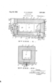
Figure 1 is a cross-section on a longitudinal plane of a cooling unit constructed in accordance with my invention.
Figure 2 is a cross-section the plane of'which is indicated by the' line 2-2 of Figure 1.
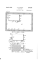
Figure 3 is a view, partly in section, showing in elevation a cooling unit installation in accordance with my invention.
Figure 4 is aside elevation of the cooling unit shown in Figure 1 with the addition of an aircirculating fan. 1
Figure 5'is ,abottom view of the structure shown in Figure 4. The cooling unit f my invention is susceptible of a wide range of variation, not only in matte'rs of construction but also in environmental conditions. with railway express car cooling, .as indicated in my co-pending application entitled Compartment car, filed July 31, 1933, with Serial No. 682,996. The range-of.v usefulness, however, is so great that I have chosen for illustration herein a typical cooling unit suitable for all-around usage.
This'unit, as illustrated, has proved particularly successful in connection with cooling produce containers on motor trucks, and comprises a housing 6 which is generally rectangularand is approximately square in transverse cross-sec tion. The housing is made up' of a pluralitrof enclosing walls generally fabricated'of a suitable One valuable use is in connection 11 Claims. (01. Git-91.5)
insulating material 1. That is, a top wall Bis comprised of insulating material I sheathed on both surfaces, for example by an outer, preferably metallic covering 9 and an inner metallic lining ll. comparably, the housing incorporates 5 a bottom wall 12 including insulatingmaterial l confined between an inner lining l3 anll an outer shell 14. An end wall [6 is similarly fabricated of an outer shell l1 and an inner shell l8 lying on opposite sides of the insulating material I. The opposite end of the housing is sealed by a closure 2i comprising a door structure including insulating material 22, an outer shell 23 and an inner lining 24. The door 2| is preferably tapered to form a tight seal with its jamb 26 and is preferably mounted on hinges 21 and provided with a suitable latch 28 to maintain the door in closed position.
The spacing of the various walls is such as to provide a chamber 28 therein for the accommodation of a solid, gas-emanating refrigerant, usually in the form of blocks 29 and 3|. Customarily, solid carbon-dioxide -is utilized as the refrigerant. This material has the property of giving off carbon-dioxide gas at suitable tempratures. This gas isconsiderably heavier than -air and naturally tends to drop if unconfined. I
preferably take advantage of such characteristic in practising my invention. To this end the standard size blocks of refrigerant 29 and 3i are 30 somewhat smaller than the internal dimensions of the chamber 28, so that gas emanating from the refrigerant tends naturally to flow downwardly in the direction of the arrows 32 through a passage 33 between the blocks 3| and the interior shell 24 of the door 2|.
Preferably forming part of the housing 6, but thermally isolated from the chamber 28, is a conduit 34. This conduit is defined by the outer shell ll of the wall l2 and by a suitably corrugated plate 36 which is customarily of metal and provides a heat exchange surface between the material within the conduit 34 and the exterior air. Theplate 36, while illustrated herein as corrugated, can be'ilat or of any suitable configuration in order to comply with the desired heat exchange characteristics.
To establish communication between the conduit 34 and the chamber 28 I provide an outlet duct 31 which pierces the bottom wall l2 and is of generally rectangular shape and of relatively large cross-sectional area. Gas flowing in the path indicated by the arrows 32 continues through the duct,asindicated by the arrows 38, and fiows through the'conduit 34 as indicated by the arrows I the cycle.
39. In order to prevent blocking of the duct 38 by shifting of the refrigerant blocks 29 and 3|, I preferably providt suitable guards or spacers 4| on the door 2 I, so that when the door is closed the blocks 29 and 3| are precluded from sliding over and blocking the duct 38.
I preferably provide means to control the flow to the duct 38, and therefore on the plate 36 I provide a threaded boss 42 within which is screwed a threaded shaft 43 carrying a suitable manipulating handle 44. A valve plate46 is mounted on the shaft 43 and can be tightly pressed against the duct 38 or can be removed therefrom in order to regulate the passage'of gas therethrough. Adjacent the boss 42 I provide a sump 41 with a drainpipe 48 and a closure cap 49 for the drainage of moisture. While solid carbon-dioxide itself is moisture-free, nevertheless certain atmospheric moisture enters the chamber 28 whenever the door 2| is opened, and after a period of time such moisture collects within the sump 4'! and is discharged through the pipe 48 upon removal of the cap 49.
Gas which travels from the duct 38 into the conduit 34 is in neat absorbing relationship to external air on the opposite side of the plate 36 and absorbs heat from such external air at a relaan inlet duct 56.piercing the end wall I6. The
passage 54 is partially formed by a closure 51 customarily fabricated of sheet metal and fitting on the end of the housing 6. The duct 56 is very much of the character of the duct 38 but is located adjacent the uppermost portion of the chamber 28, so that the relatively light, warmed gas can return in a favorable location. Gas which returns through the duct 56, as indicated by the arrow 58, is quickly reduced in temperature by thermal proximity to the refrigerant blocks 29 and 3| and quickly recycles in the path of the arrows 32 and 39 as previously described.
In the mentioned fashion there is provided convection circulation in a closed cycle, with heat absorption through the conduit 36 and return of the warmed gases to the relatively cold chamber 28. The pressure existing in the circuit is substantially atmospheric and, in order to maintain such pressure and to provide for the escape of gas which is relatively high in temperature and which is no longer useful, I provide an outlet pipe 59 at substantially the highest thermal point in The pipe 59 opens into the upper portion of the duct 54 and, while most of the warm gas adjacent the duct 56 is sufliciently cooled by the refrigerant blocks 29 and 3| to enter the duct 56 and recycle, certain of the gas which is too high in temperature is not sufficiently cooled and flows out through the discharge pipe 59 which communicates with the atmosphere.
In order that flow through the duct 56 will not be blocked by the refrigerant cubes 29 and 3|, I provide suitable spacers 6| on the end wall I6, so that the duct 56 affords a free passage for the returning gas. In accordance with my invention, however, I desire to vary or restrict the circulation of the gas in order to adjust the temperature within the conduit 34 so that the desired cooling rate can be obtained. To this end I preferably let I28 discharges.
restrict the entrance of duct 56 by a valve 62 which can be operated in a suitable fashion. Ordinarily, the valve 62 is operated in response to the temperature of the returning gas within the passage 54. To this end the plate 82 is mounted on a bimetallic strip 83 or other suitable thermostat which is anchored as at 64 on, the casing 51.
In order to control the temperature at which the thermostat 63 is especially responsive, I provide a cross-shaft 66 which projects from the casing 57 and carries a manual operating handle 68 or other suitable actuating device. Mounted on the shaft 66 is an eccentric 69 adapted to abut the strip 63 and thus govern the position of the plate 62 and the temperatures at which the plate 62 is especially effective. By suitably manipulating the handle 68 the maximum rate of flow of the refrigerant can be governed. The temperature within the space or enclosure cooled by the cooling unit of my invention is held within very close limits by the thermostat. I have found from extensive practice that a device constructed with approximately the proportions shown, espee cially with the insulation in the walls 8 and the door 22 somewhat thicker than the insulation in the walls I6 and I2 adjacent the heat exchange members 34 and 51, provides a suitable range of operating temperatures.
While the unit as shown in Figures 1 and 2- is suitable for general installation, when the cooling unit is installed within an insulated chamber I prefer to provide certain modifications. As illustrated in Figure 3, the cooling unit, generally designated IOI, is disposed within an insulated chamber 02 having walls I03 formed of an outer shell' I04"and an inner shell I06. Genierally, the
space'betWeen theinner and outer w'allsis filled with any standard heat-insulating material I01. In accordance with my'invention, the o'utlet'pipe I08 'forspent gases from the cooling unit IOI, is
tapped through the inner wall-I06 to discharge "into the insulation material I 01 between the inner'and outer walls I06 and I04, respectively. Such discharged gas is usually still lower in temperature than the temperature obtaining within the compartment I02, while carbon-dioxide gas itself is a good heat insulation material. The gas discharged into the,space betweenthe walls I04 and I06 is compelled to pass completely around the chamber I02 to discharge from an outlet pipe I 09 into the atmosphere, the direction of circulation being indicated by the arrows III. A baflle II2 prevents short-circuiting of the gas between thepipes I 08 and |09.'
While under most conditions of operation the natural, exterior circulation past the heat exchange surface 36 is ample, nevertheless under certain circumstances I desire to accelerate such air flow and thereby obtain an enhanced rate of heat exchange. To this end I preferably mount a fan of any suitable character on the cooling unit itself. As illustrated in Figures 4 and 5, a cooling unit I2I is provided with a heat exchange surface I22 of corrugated contour. The unit includes a casing I23 to which a suitable ,motor I24 is mechanically attached. The motor I24 is part of a blower having a scroll housing I26 to which an air inlet I 21 leads and from which an air out- The direction of discharge of the outlet I28 is such as to cause a current of air induced to flow through the inlet I2'I to spread out and flow along the corrugated surface I22, thereby providing an accelerated heat transfer through the surface.
exposed heat-exchanging surface along one side of said chamber, a duct establishing communication between the lower part of said chamber and .said conduit, a second duct establishing communication between said conduit and the upper part of said chamber, and thermostatic means disposed within one of said ducts responsive-to the temperature of the gas circulating in said conduit for controlling the flow of gas therethrough. r
2. A cooling unit comprising a heat insulated housing having a chamber therein for containing a solid gas-emanating refrigerant, a metallic partition having an exposed heat absorbing surface arranged in spaced relation along the bottom of said housing, a plurality of ducts piercing said heat insulated housing for establishing communication for a convection circulation of gas between said housing and said metallic partition, and thermostatic means responsive to the temperature of the circulating gas for controlling the rate of heat absorption of said metallic partition.
3. A self contained cooling unit for refrigerating purposes comprising a housing of heat insulating material having a chamber therein for holding a solid gas-emanating refrigerant, a corrugated metallic wall disposed in spaced relation along the bottom of said housing and forming a conduit having an exposed heat-exchanging surface, a plurality of ducts extending through the heat insulating material forming said housing for establishing communication for a convection circulation and recirculation of gas through said chamber and between said housing and said corrugated metallic wall, and thermostatic means in said conduit for controlling the rate of the circulation of said gas.
4. A cooling unit comprising a heat insulated housing having a chamber therein for containing a solid gas-emanating refrigerant, a metallic partition having an exposed heat absorbing surface arranged in spaced relation along the bottom of said housing, inlet and outlet ducts piercing said heat insulated housing for establishing communication for a convection circulation of gas between said housing and said metallic partition, a manually controlled valve in said outlet duct, and a thermostatically controlled valve responsive to the temperature of the circulatinggas in said inlet duct, said valves being operable to control the rate of heat absorption of said metallic partition.
5. A cooling unit comprising a housing of heat insulating material having a chamber therein for containing a solid gas-emanating refrigerant, a conduit having an exposed heat-exchanging surface arranged outside of and below said housing, a duct in the bottom of said chamber establishing communication between said chamber and said conduit, a door adjacent said duct for the introduction of the solid gas-emanating refrigerant, and means carried by said door for holding said solid gas-emanating refrigerant clear of said duct without interfering with the free flow of gas therethrough.
6. A self contained solid carbon dioxide refrigerating unit comprising a housing of heat insulating material having a chamber for holding a quantity of solid carbon dioxide, means forming a conduit having heat-exchanging properties through which the gas emanating from said solid carbon dioxide may circulate and recirculate by convection, and thermostatic means within said conduit responsive to the temperature of the circulating gas for controlling the recirculation of gas therethrough.
7. A self contained cooling unit for refrigerating purposes comprising a housing of heat insulating material having a chamber for holding a solid gas-emanating refrigerant, means forming a conduit having heat-exchanging properties through which the gas emanating from said solid refrigerant may circulate by convection, thermostatic means within said conduit for controlling the circulation of gas therethrough, and means for regulating the range of said thermostatic means during operation whereby the rate of gas emanation from said solid refrigerant may be determined at any time irrespective of the external temperature.
B. A solidified carbon dioxide refrigerating unit comprising a housing of heat insulating material having a chamber therein for containing a quantity of solid carbon dioxide, a heat conducting wall disposed in spaced relation with said housing and forming an exposed heat-exchanging surface below said chamber, means establishing communication batlween the interior of said chamber and the side of said heat conducting wall for a closed-cycle convection circulation of the gas emanating from said solid carbon dioxide, and thermostatic means responsive to the temperaturevariations of the circulating gas for controlling the flow thereof and thereby the rate of sublimation of said solid carbon dioxide independently of the temperature external to' said exposed heat-exchanging surface.
9. A solidified carbon dioxide refrigerating unit comprising a housing of heat insulating material having a chamber therein for containing a solid carbon dioxide, a heat conducting wall disposed in spaced relation with said housing and forming a conduit for a closed-cycle circulation of carbon dioxide gas having an exposed heat-exchanging surface arranged belowsaid chamber, means for establishing communication between said chamber and said conduit to permit a circulation of gas evolved from said solid carbon dioxide, and a thermostatically controlled valve responsive to the temperature within said conduit for controlling the circulation of the gas therethrough, whereby the rate of gas emanation from said solid carbon dioxide will be determined by the heat absorbed by the gas from said heat-exchanging surface.
10. A solidified gas refrigerating unit comprising a housing of heat insulating material having achamber therein for containing a solid gasemanating refrigerant, a conduit having an exposed heat-exchanging surface arranged outside of and below said housing, a duct establishing a path for gas evolved from said solid refrigerant extending from the lower part of said chamber to said conduit, a second duct establishing a path from said conduit to the upper part of said chamber, said ducts cooperating with said chamber and said conduit to provide a closed-cycle circulation of the gas emanating from-said solid refrigerant, and a thermostatically controlled valve. responsive to the temperature of the circulating gas for controlling the recirculation thereof and thereby the rate of sublimation of said solid refrigerant independently of the temperature external to said housing.
11. A cooling unit comprising a heat insulated housing having a chamber therein for containing a solid gas-emanating refrigerant, a metallic partition having an exposed heat absorbing surface arranged in spaced relation along the bottom of said housing, inl-etand outlet ducts piercing said heat insulated housing for establishing communicationfor a convection circulation and recirculation of gas between said housing and said metallic partition, a manually controlled valve in said outlet duct ,forcgntrolling the discharge of gas from said chamber, and a thermostatically controlled valve responsive to the temperature of the gas circulating between said housing and said metallic partition, said manually controlled valve being operable to control the rate of circulation of said gas from said chamber and said thermostatically controlled valve being operable to control the rate of recirculation of said gas, whereby the heat absorption ability of said metallic partition will be determined.
WILLIAM M. STEWART.
I DISCLAIM ER 2 011,881.William M. Stewart, San Francisco, Calif. COOLING UNIT. Patent dated August 20, 1935. Disclaimer filed July 22, 1939, by the assignee, Controlled Rqfrigerants Company Ltd.
Hereby enters this disclaimer to wit: any interpretation of claim 1 that will include a structure wherein the thermostatic means is not located in a duct remote from the ex osed heat-exchanging surface and is not controlled in its automatic operation so ely by temperature changes of the gas circulating through the duct in which the thermostatic means is located.
[Oficial Gazette August 22, 1989.]
Priority Applications (1)
| Application Number | Priority Date | Filing Date | Title |
|---|---|---|---|
| US682997A US2011881A (en) | 1933-07-31 | 1933-07-31 | Cooling unit |
Applications Claiming Priority (1)
| Application Number | Priority Date | Filing Date | Title |
|---|---|---|---|
| US682997A US2011881A (en) | 1933-07-31 | 1933-07-31 | Cooling unit |
Publications (1)
| Publication Number | Publication Date |
|---|---|
| US2011881A true US2011881A (en) | 1935-08-20 |
Family
ID=24742124
Family Applications (1)
| Application Number | Title | Priority Date | Filing Date |
|---|---|---|---|
| US682997A Expired - Lifetime US2011881A (en) | 1933-07-31 | 1933-07-31 | Cooling unit |
Country Status (1)
| Country | Link |
|---|---|
| US (1) | US2011881A (en) |
Cited By (6)
| Publication number | Priority date | Publication date | Assignee | Title |
|---|---|---|---|---|
| US2435854A (en) * | 1945-05-07 | 1948-02-10 | Nasa | Apparatus for the freezing-drying of tissues |
| US2880971A (en) * | 1957-02-21 | 1959-04-07 | Gen Motors Corp | Refrigerator butter compartment |
| US2958207A (en) * | 1958-11-03 | 1960-11-01 | Braneky Stephen | Air cooling system |
| US3001383A (en) * | 1959-05-25 | 1961-09-26 | Ryan Aeronautical Co | Pressurized air cooler |
| US3800554A (en) * | 1972-05-15 | 1974-04-02 | Kardel Prod Corp | Food storage and cooling apparatus |
| US5323622A (en) * | 1993-04-21 | 1994-06-28 | Cryo-Trans, Inc. | Multi-temperature cryogenic refrigeration system |
-
1933
- 1933-07-31 US US682997A patent/US2011881A/en not_active Expired - Lifetime
Cited By (7)
| Publication number | Priority date | Publication date | Assignee | Title |
|---|---|---|---|---|
| US2435854A (en) * | 1945-05-07 | 1948-02-10 | Nasa | Apparatus for the freezing-drying of tissues |
| US2880971A (en) * | 1957-02-21 | 1959-04-07 | Gen Motors Corp | Refrigerator butter compartment |
| US2958207A (en) * | 1958-11-03 | 1960-11-01 | Braneky Stephen | Air cooling system |
| US3001383A (en) * | 1959-05-25 | 1961-09-26 | Ryan Aeronautical Co | Pressurized air cooler |
| US3800554A (en) * | 1972-05-15 | 1974-04-02 | Kardel Prod Corp | Food storage and cooling apparatus |
| US5323622A (en) * | 1993-04-21 | 1994-06-28 | Cryo-Trans, Inc. | Multi-temperature cryogenic refrigeration system |
| US5415009A (en) * | 1993-04-21 | 1995-05-16 | Cryo-Trans, Inc. | Cryogenic refrigeration system with insulated floor |
Similar Documents
| Publication | Publication Date | Title |
|---|---|---|
| US3590594A (en) | Single evaporator multiple temperature refrigerator | |
| US3263440A (en) | Refrigeration | |
| US2292032A (en) | Refrigerator cabinet | |
| US2196310A (en) | Air cooler | |
| US4138859A (en) | Split heat pump outdoor fan arrangement | |
| US2336735A (en) | Removable cooling unit for compartments | |
| US2011881A (en) | Cooling unit | |
| US2713995A (en) | Air heating and cooling system | |
| US3529435A (en) | Air cooler for automobile | |
| US1975868A (en) | Method of cooling indirectly | |
| US2314657A (en) | Refrigerator | |
| US2647374A (en) | Antisweat antifrost attachment | |
| US3021688A (en) | Butter storage in refrigerators | |
| JPS57138415A (en) | Car-loaded refrigerator | |
| US1705928A (en) | Method of and apparatus for preventing the condensation of moisture on the exterior surface of refrigerator cabinets | |
| US2317775A (en) | Refrigeration apparatus | |
| US3188831A (en) | Refrigeration | |
| US1902246A (en) | Air cooling | |
| US2419477A (en) | Air conditioning | |
| US1764194A (en) | Controlling device for heat transference in refrigerators | |
| US2469179A (en) | Refrigeration | |
| US2209604A (en) | Cooling device | |
| US2107538A (en) | Refrigerator | |
| US2509784A (en) | Condensation preventing means for refrigerators | |
| US2164677A (en) | Cold chest |