US2011868A - Head lamp - Google Patents
Head lamp Download PDFInfo
- Publication number
- US2011868A US2011868A US718589A US71858934A US2011868A US 2011868 A US2011868 A US 2011868A US 718589 A US718589 A US 718589A US 71858934 A US71858934 A US 71858934A US 2011868 A US2011868 A US 2011868A
- Authority
- US
- United States
- Prior art keywords
- lens
- housing
- lip
- lamp
- flange
- Prior art date
- Legal status (The legal status is an assumption and is not a legal conclusion. Google has not performed a legal analysis and makes no representation as to the accuracy of the status listed.)
- Expired - Lifetime
Links
- 238000010276 construction Methods 0.000 description 3
- 239000002184 metal Substances 0.000 description 2
- 230000004048 modification Effects 0.000 description 2
- 238000012986 modification Methods 0.000 description 2
- 238000007789 sealing Methods 0.000 description 2
- 238000000926 separation method Methods 0.000 description 2
- 230000000712 assembly Effects 0.000 description 1
- 238000000429 assembly Methods 0.000 description 1
- 230000000149 penetrating effect Effects 0.000 description 1
- XLYOFNOQVPJJNP-UHFFFAOYSA-N water Substances O XLYOFNOQVPJJNP-UHFFFAOYSA-N 0.000 description 1
Images

Classifications
-
- F—MECHANICAL ENGINEERING; LIGHTING; HEATING; WEAPONS; BLASTING
- F21—LIGHTING
- F21V—FUNCTIONAL FEATURES OR DETAILS OF LIGHTING DEVICES OR SYSTEMS THEREOF; STRUCTURAL COMBINATIONS OF LIGHTING DEVICES WITH OTHER ARTICLES, NOT OTHERWISE PROVIDED FOR
- F21V17/00—Fastening of component parts of lighting devices, e.g. shades, globes, refractors, reflectors, filters, screens, grids or protective cages
- F21V17/10—Fastening of component parts of lighting devices, e.g. shades, globes, refractors, reflectors, filters, screens, grids or protective cages characterised by specific fastening means or way of fastening
- F21V17/12—Fastening of component parts of lighting devices, e.g. shades, globes, refractors, reflectors, filters, screens, grids or protective cages characterised by specific fastening means or way of fastening by screwing
-
- F—MECHANICAL ENGINEERING; LIGHTING; HEATING; WEAPONS; BLASTING
- F21—LIGHTING
- F21S—NON-PORTABLE LIGHTING DEVICES; SYSTEMS THEREOF; VEHICLE LIGHTING DEVICES SPECIALLY ADAPTED FOR VEHICLE EXTERIORS
- F21S41/00—Illuminating devices specially adapted for vehicle exteriors, e.g. headlamps
- F21S41/20—Illuminating devices specially adapted for vehicle exteriors, e.g. headlamps characterised by refractors, transparent cover plates, light guides or filters
- F21S41/29—Attachment thereof
-
- F—MECHANICAL ENGINEERING; LIGHTING; HEATING; WEAPONS; BLASTING
- F21—LIGHTING
- F21S—NON-PORTABLE LIGHTING DEVICES; SYSTEMS THEREOF; VEHICLE LIGHTING DEVICES SPECIALLY ADAPTED FOR VEHICLE EXTERIORS
- F21S41/00—Illuminating devices specially adapted for vehicle exteriors, e.g. headlamps
- F21S41/30—Illuminating devices specially adapted for vehicle exteriors, e.g. headlamps characterised by reflectors
- F21S41/39—Attachment thereof
Definitions
- doorle'ss headlamp of simple -construction so that the lens may be readily removed. whenever desired but nevertheless one so well constructed that the parts are at alltimes held tightly-together'and well sealed, preventing the entrance of fdust or water.
- the invention is characterizedby the'iact that the lens is secured-y di'rectly to the lamp'housing, beingprovide'd at one edge withfa projectionor notch interlocking with" the housing and at the opposite edge .
- suitable fastening means which serves to draw the lens into'engag'ement withthe' open end 'ofthe housingf
- springpr'esjsure is so applied as to urge the lens outwardly 'and thisspring pressure is likewise preferably utilized to yieldingly urge a sealing gasket ag'ainst,the-lens.
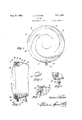
- FIG. 1 is a front elevation of a headlamp embodying the invention
- Figure 2 is a side View, partly in section.
- Figure 3 is aperspective View of thele'ns engag- Figure 4 is a vertical section I showing a modified Figure 5 is afrag'mentary section corresponding tothe upper part of Figure 2 but showing a modiiF atiOn.
- Figure 6 is a vertical section with partsbroken away-showing a further modification.
- Figure 7 is a front view of the lamp of",Fig'- ure6.' V
- Figure 8' is'asectional view showing a'modi fication of the securingmeans at the bottom'of the lens.
- the head lamplhousing. it is provided on its upper portion with inturned flange l2 preferably crescent shaped when viewed from the front.
- the housing ispflx'ed an angledring. wi l adapted to support the flange it of the usual reflector i8.
- the reflector is preferably located with respect to the housing by means of pin Zii secured to the edge of thereflector' and passing through a slot in'the vertical flange oi the ring i4.
- Bowed leaf springs such as tained; 4- v In; the formshown in Figures 6 and 7, the lensis Qprovided with-an arcuate projectioniw, which, a combination with the adjacent portion of the shownv at .21. are provided between, the flange .of therefiector andthe ring M, the springs having theirfr'ee endsinzengagement with the flange and theirintermediate portions engaging the back of thereflector flange; Three springs are provided,
- the springs urge the'reflector toward the opening in the housing.
- the edge of the reflector 18 is preferably'channelled as shown to receive the sealing gasket. 22. .
- the bottom ofthe lens is provided with a socket 28 adapted to receivea clip 38, shown in detail in Figure 3.
- the clip is clampedto the housing by means ofstamping tzjclamped'to (bracket 34 secured to the housing, by. screw bolt 3.6. If desired the clip-3d; and stamping32 may be'made in one pieceas shown atSB'in Figure 4. Lug 39 holds the'clip to the lens.
- I prefer to provide three or" the pin assemblies, one at the top and one at each'side of the lamp, while the lamp is held at the bottom by means of a clip I04 engaging socket I05 in the lens as in the precedingv figures.
- the securing means for clip I04 consists of screw bolt I06 passing 'through an aperture in the clip and threaded at It! in stamping I08 secured to the lamp housing as by riveting over an outturned annular flange I 10 formed'out of the metal of the stamping.
- Coil spring II2 engages collar II 4.0n the bolt I06 and yieldingly" resists outward movement of the bolt.
- a headlamp comprising a housing provided "at one side of the diameter with an overhanging lip, a lens having. an'edgeportion adapted to engage said lip and means engaging an indenture in the lens at the other side thereof to clamp thelens to the housing;
- a headlamp In a headlamp the combination of a housing provided at its open end with a crescent shaped overhanging lip, a lens having a marginal portion adapted to engage said lip, means at the other side of the housing engaging an indenture in the lens for olampingthe lens thereto, and resilient means within the housingfor yieldingly urging the lensfoutwardly thereof.
- a headlamp the combination of a housing provided at its open end with an overhanging lip,'a lens having a marginal portion adapted to engagesaid lip, ail-abutment secured within the 7 housing, yielding means engaging the abutment and urging the lens out of the housing, and means at the side 0f the housing opposite the lip engaging an indenture in the lens and clamping it thereto.
- a headlamp the combination of a housing provided at its open end with an overhanging lip, a lens having a marginal portion adapted to engage said lip, an abutment secured within the housing, a reflector in the housing having a flange overlying the abutment, means yieldingly urging the reflector away from the abutment, said refi'ecto'rbear'i'ng against the lens and tending to urge it out of the housing, and means at the side of the housing opposite the lip engaging.an indenture in the lens and clamping it thereto.
- Aheadlamp comprising a housing having a lens receivihgopehing, and a lens fitting in the aperture in the housing, and provided at one side with means ior interlockingwith the housing to prevent axial separation thereof, and means at the other side of the lamp engaging an indenture-inthe lens for drawing the lens toward the housing and into clamping engagement therewith.
- Aheadlamp comprising a housing having a lens receiving. opening, a ringwithin the housing, a lens'provided. at one side thereof with means for interlocking with'the edge of the opening to prevent axial separation of the lens and a housing, means at theother side of the lens .engaging an indenture therein for drawing the lens ing a grooved portion into which the 1mm adapted to fit, a second short' 'groove; diametrically opposite the first and penetrating at right angles to the first groove in the lens, and aclamp member secured 'to the housing having Va tongue adapted to engage the second groove to hold the lens in place.
- a rifnless headlamp comprising a housing having in one end a circular opening, a crescent lip overhanging one side of the opening, a lens adapted 'to engage the lip to supportone side of the former against the housing, a short groove in the lens'opposite the hp, 1 and clamping means engageable in'the groove, said means including a multi-angled strip the opposite end of which engages ascrew threaded into an extension of the casing.
- a headla p comprising a housing having a lens receivingopeningan overhanging lip on one sideof the opening, 'a lens adapted to engage the lip to support one side of the former against the housing, a multi-angular clamp engaging an indenture in the opposite side of the lens and a springbiased bolt; concealed within a pressed-in portionr of the housing securing the opposite end of the cl-ampto complete the assembly.
Landscapes
- Engineering & Computer Science (AREA)
- General Engineering & Computer Science (AREA)
- Non-Portable Lighting Devices Or Systems Thereof (AREA)
Description
Aug 2% v MICHEL HEAD LAMP- I Filed April 2, 1954 2 Sheets-Sheet l Au 20,1935. a, A, WCH E; 2,011,868
HEAD LAMP Filed April 2, 1954 2 Sheets-Sheet 2 Patented Aug. 20, 1935 2,911,868 HEAD LAMP I Clarence A. Michel, Anderson, Incl, assignor to "General Motors CorporatiomiDetroit, Mich;, a i
' corporation of'Delaware I I .fApplication April 2, 1934, Serial o. 718,589,".
doorle'ss headlamp of simple -construction so that the lens may be readily removed. whenever desired but nevertheless one so well constructed that the parts are at alltimes held tightly-together'and well sealed, preventing the entrance of fdust or water. r
The invention is characterizedby the'iact that the lens is secured-y di'rectly to the lamp'housing, beingprovide'd at one edge withfa projectionor notch interlocking with" the housing and at the opposite edge .with suitable fastening means which serves to draw the lens into'engag'ement withthe' open end 'ofthe housingf To maintain the parts in engagement, springpr'esjsure is so applied as to urge the lens outwardly 'and thisspring pressure is likewise preferably utilized to yieldingly urge a sealing gasket ag'ainst,the-lens. j y
In the drawings: 1 Figure 1 is a front elevation of a headlamp embodying the invention;
ing clip shown in Figure 2.
form of clip;
Figure 2 is a side View, partly in section. Figure 3 is aperspective View of thele'ns engag- Figure 4 is a vertical section I showing a modified Figure 5 is afrag'mentary section corresponding tothe upper part of Figure 2 but showing a modiiF atiOn.
Figure 6 is a vertical section with partsbroken away-showing a further modification.
Figure 7 is a front view of the lamp of",Fig'- ure6.' V
Figure 8' is'asectional view showing a'modi fication of the securingmeans at the bottom'of the lens. I In the'form shownin Figures 1 to 4 the head lamplhousing. it] is provided on its upper portion with inturned flange l2 preferably crescent shaped when viewed from the front. ,Within the housing ispflx'ed an angledring. wi l adapted to support the flange it of the usual reflector i8. The reflector is preferably located with respect to the housing by means of pin Zii secured to the edge of thereflector' and passing through a slot in'the vertical flange oi the ring i4. Bowed leaf springs such as tained; 4- v In; the formshown in Figures 6 and 7, the lensis Qprovided with-an arcuate projectioniw, which, a combination with the adjacent portion of the shownv at .21. are provided between, the flange .of therefiector andthe ring M, the springs having theirfr'ee endsinzengagement with the flange and theirintermediate portions engaging the back of thereflector flange; Three springs are provided,
I equally spaced about the circumference.v of the. flang'em .The springs urge the'reflector toward the opening in the housing. The edge of the reflector 18 is preferably'channelled as shown to receive the sealing gasket. 22. .The lens Mismounted in the headlamp by inserting its upper edge portion,
the reflector rearwardly against the resistance of springsvzlhv The bottom ofthe lens isprovided with a socket 28 adapted to receivea clip 38,, shown in detail in Figure 3. The clip is clampedto the housing by means ofstamping tzjclamped'to (bracket 34 secured to the housing, by. screw bolt 3.6. If desired the clip-3d; and stamping32 may be'made in one pieceas shown atSB'in Figure 4. Lug 39 holds the'clip to the lens.
'With this construction theusual lens ring is "omitted, its function being performed by the flange on thelhousing. and the clip til-32 ores. At the same time the. 1 appearance of the lamp is improved; and all of this is accomplished with a considerable reduction in cost.
pressedoutof the metal .of the. ring Mt: With this construction the flange I2 is, unnecessary so thatthe appearance of the lamp is furtherenhanc'ed since the usual circular .lens opening is re lens, forms a slot 9| in which is received the inturned flange of the lamp housing. In this modi- "WhichJmay' take the formbf a flangefifi, behind I the, flange 12, this being accomplished by pressing fication there isfixedly secured within the headlamp a split'ringiill L-shap'ed injcross section;
Therefiec'tor 94 is'pro'vided with the usual gasket "receiving groove 96. The reflector is secured to the split ring 92 by fastening means'in the form of, pins 95 projecting through apertures in the base of the groove 96 and through alinedapertures.
aresecured-enlargements 93"00 prevent their Withdrawal. Springs I09 encircle the pins W5 and of the ring 92. a
in the split ring 92; To the ends or the pins As shown in Figure '7 I prefer to provide three or" the pin assemblies, one at the top and one at each'side of the lamp, while the lamp is held at the bottom by means of a clip I04 engaging socket I05 in the lens as in the precedingv figures. The securing means for clip I04 consists of screw bolt I06 passing 'through an aperture in the clip and threaded at It! in stamping I08 secured to the lamp housing as by riveting over an outturned annular flange I 10 formed'out of the metal of the stamping. Coil spring II2 engages collar II 4.0n the bolt I06 and yieldingly" resists outward movement of the bolt. It will be apparent that by rotating bolt I06 in a direc tion to compress spring H2, clip I04 is released; so that itmay be disengaged from socket I05} lock between lens and housing. It is clear of course thatthe lens holding devices need not be at the top and bottom of the lamp but may be at opposite sides. .More than one lens retaining 'clampmay be used if desired.
' Obviously in place of the rings shown at I4 in Figure 2 and at 92 in Figure. 6; a plurality of circumferentially spaced clips may be employed, these clips being suitably welded or soldered to the body- This really amountszto no more than making the rings discontinuous. 1
I claim: '3
1. A headlamp comprising a housing provided "at one side of the diameter with an overhanging lip, a lens having. an'edgeportion adapted to engage said lip and means engaging an indenture in the lens at the other side thereof to clamp thelens to the housing;
2. The combination as defined in claim 1, means 'for resiliently pressing the lens against the lip.
3.The combination .of a housing providedat one side thereof with an overhanging lip, a reflector within the housing, means for resiliently pressing the reflectortoward the open end of the housing and a lens havinga'portion. adapted to engage the lip and to be-yieldingly. engaged by the reflector and means engaging an indenture in'the other side of the housing for clamping th lens thereto.
4.' In a headlamp the combination of a housing provided at its open end with a crescent shaped overhanging lip, a lens having a marginal portion adapted to engage said lip, means at the other side of the housing engaging an indenture in the lens for olampingthe lens thereto, and resilient means within the housingfor yieldingly urging the lensfoutwardly thereof.
5. Ina headlamp, the combination of a housing provided at its open end with an overhanging lip,'a lens having a marginal portion adapted to engagesaid lip, ail-abutment secured within the 7 housing, yielding means engaging the abutment and urging the lens out of the housing, and means at the side 0f the housing opposite the lip engaging an indenture in the lens and clamping it thereto.
6. In a headlamp, the combination of a housing provided at its open end with an overhanging lip, a lens having a marginal portion adapted to engage said lip, an abutment secured within the housing, a reflector in the housing having a flange overlying the abutment, means yieldingly urging the reflector away from the abutment, said refi'ecto'rbear'i'ng against the lens and tending to urge it out of the housing, and means at the side of the housing opposite the lip engaging.an indenture in the lens and clamping it thereto.
7. Aheadlamp comprising a housing having a lens receivihgopehing, and a lens fitting in the aperture in the housing, and provided at one side with means ior interlockingwith the housing to prevent axial separation thereof, and means at the other side of the lamp engaging an indenture-inthe lens for drawing the lens toward the housing and into clamping engagement therewith.
8. Aheadlamp comprising a housing having a lens receiving. opening, a ringwithin the housing, a lens'provided. at one side thereof with means for interlocking with'the edge of the opening to prevent axial separation of the lens and a housing, means at theother side of the lens .engaging an indenture therein for drawing the lens ing a grooved portion into which the 1mm adapted to fit, a second short' 'groove; diametrically opposite the first and penetrating at right angles to the first groove in the lens, and aclamp member secured 'to the housing having Va tongue adapted to engage the second groove to hold the lens in place. g V h s 11. A rifnless headlamp comprisinga housing having in one end a circular opening, a crescent lip overhanging one side of the opening, a lens adapted 'to engage the lip to supportone side of the former against the housing, a short groove in the lens'opposite the hp, 1 and clamping means engageable in'the groove, said means including a multi-angled strip the opposite end of which engages ascrew threaded into an extension of the casing. I v
12. A headla p comprising a housing having a lens receivingopeningan overhanging lip on one sideof the opening, 'a lens adapted to engage the lip to support one side of the former against the housing, a multi-angular clamp engaging an indenture in the opposite side of the lens and a springbiased bolt; concealed within a pressed-in portionr of the housing securing the opposite end of the cl-ampto complete the assembly.
1 a CLARENCE A. MICHEL.
Priority Applications (1)
| Application Number | Priority Date | Filing Date | Title |
|---|---|---|---|
| US718589A US2011868A (en) | 1934-04-02 | 1934-04-02 | Head lamp |
Applications Claiming Priority (1)
| Application Number | Priority Date | Filing Date | Title |
|---|---|---|---|
| US718589A US2011868A (en) | 1934-04-02 | 1934-04-02 | Head lamp |
Publications (1)
| Publication Number | Publication Date |
|---|---|
| US2011868A true US2011868A (en) | 1935-08-20 |
Family
ID=24886657
Family Applications (1)
| Application Number | Title | Priority Date | Filing Date |
|---|---|---|---|
| US718589A Expired - Lifetime US2011868A (en) | 1934-04-02 | 1934-04-02 | Head lamp |
Country Status (1)
| Country | Link |
|---|---|
| US (1) | US2011868A (en) |
Cited By (5)
| Publication number | Priority date | Publication date | Assignee | Title |
|---|---|---|---|---|
| DE938139C (en) * | 1941-06-09 | 1956-01-26 | Bosch Gmbh Robert | Headlights, especially for vehicles |
| US2734129A (en) * | 1956-02-07 | Vehicle headlight attachment | ||
| US2769082A (en) * | 1953-03-30 | 1956-10-30 | Westinghouse Electric Corp | Lighting fixture |
| US2910576A (en) * | 1957-03-15 | 1959-10-27 | Gen Electric | Vehicle headlamp mounting |
| US4177504A (en) * | 1977-11-04 | 1979-12-04 | General Electric Company | Luminaire reflector mounting for rotation of asymmetric reflector |
-
1934
- 1934-04-02 US US718589A patent/US2011868A/en not_active Expired - Lifetime
Cited By (5)
| Publication number | Priority date | Publication date | Assignee | Title |
|---|---|---|---|---|
| US2734129A (en) * | 1956-02-07 | Vehicle headlight attachment | ||
| DE938139C (en) * | 1941-06-09 | 1956-01-26 | Bosch Gmbh Robert | Headlights, especially for vehicles |
| US2769082A (en) * | 1953-03-30 | 1956-10-30 | Westinghouse Electric Corp | Lighting fixture |
| US2910576A (en) * | 1957-03-15 | 1959-10-27 | Gen Electric | Vehicle headlamp mounting |
| US4177504A (en) * | 1977-11-04 | 1979-12-04 | General Electric Company | Luminaire reflector mounting for rotation of asymmetric reflector |
Similar Documents
| Publication | Publication Date | Title |
|---|---|---|
| US2011868A (en) | Head lamp | |
| US2286448A (en) | Lamp mount | |
| US2283934A (en) | Lamp socket | |
| US2208437A (en) | Lamp socket | |
| US2175918A (en) | Direction signal lamp | |
| US1884076A (en) | Lamp door clamp arrangement | |
| US2110135A (en) | Electric lighting means | |
| US3806721A (en) | Flush mounted vehicle lamp | |
| US2106144A (en) | Dome light assembly | |
| US1031976A (en) | Attachment for incandescent electric lamps. | |
| US3743829A (en) | Rotary holder for lighting fittings | |
| US1414088A (en) | Glass fastening for automobile lamps | |
| US2032595A (en) | Mounting for reflector buttons | |
| US3518619A (en) | Lamp socket | |
| US2344716A (en) | Lamp construction | |
| US1590017A (en) | Automobile headlight | |
| US1609840A (en) | Casing having light-transmitting closures | |
| US1613906A (en) | Screw retainer | |
| US2110131A (en) | Attachable socket for fixed focus lamps | |
| US2003687A (en) | Headlight | |
| US2611000A (en) | Panel mounted lamp socket | |
| US2004142A (en) | Adjustable neck reflector | |
| US2138077A (en) | Lighting unit mounting | |
| US1278808A (en) | Lamp-shade holder. | |
| US3626359A (en) | Lamp socket |