US2011827A - Conveyer - Google Patents
Conveyer Download PDFInfo
- Publication number
- US2011827A US2011827A US635035A US63503532A US2011827A US 2011827 A US2011827 A US 2011827A US 635035 A US635035 A US 635035A US 63503532 A US63503532 A US 63503532A US 2011827 A US2011827 A US 2011827A
- Authority
- US
- United States
- Prior art keywords
- conveyer
- deflector
- branch
- lane
- articles
- Prior art date
- Legal status (The legal status is an assumption and is not a legal conclusion. Google has not performed a legal analysis and makes no representation as to the accuracy of the status listed.)
- Expired - Lifetime
Links
- 230000007246 mechanism Effects 0.000 description 56
- 230000004888 barrier function Effects 0.000 description 33
- 239000004579 marble Substances 0.000 description 13
- 238000009877 rendering Methods 0.000 description 9
- 238000010586 diagram Methods 0.000 description 4
- 239000008188 pellet Substances 0.000 description 4
- 229910052729 chemical element Inorganic materials 0.000 description 2
- 108091006146 Channels Proteins 0.000 description 1
- 238000009429 electrical wiring Methods 0.000 description 1
- 230000005484 gravity Effects 0.000 description 1
- 238000005065 mining Methods 0.000 description 1
- 239000011435 rock Substances 0.000 description 1
Images


Classifications
-
- B—PERFORMING OPERATIONS; TRANSPORTING
- B65—CONVEYING; PACKING; STORING; HANDLING THIN OR FILAMENTARY MATERIAL
- B65G—TRANSPORT OR STORAGE DEVICES, e.g. CONVEYORS FOR LOADING OR TIPPING, SHOP CONVEYOR SYSTEMS OR PNEUMATIC TUBE CONVEYORS
- B65G47/00—Article or material-handling devices associated with conveyors; Methods employing such devices
- B65G47/34—Devices for discharging articles or materials from conveyor
- B65G47/46—Devices for discharging articles or materials from conveyor and distributing, e.g. automatically, to desired points
- B65G47/50—Devices for discharging articles or materials from conveyor and distributing, e.g. automatically, to desired points according to destination signals stored in separate systems
- B65G47/503—Devices for discharging articles or materials from conveyor and distributing, e.g. automatically, to desired points according to destination signals stored in separate systems the system comprising endless moving means
Definitions
- This invention relates to an improvement in conveyers and more particularly in a conveyer system including a plurality of deflectors or other direction determining devices.
- the primary object of this invention resides in the provision. of a mechanism under the control of the operator and comprising a plurality of chutes each adapted to receive an element such as a marble or pellet and a plurality of trips each of which automatically actuates a selected defiector or direction determining device, each trip being associated with a particular chute and being engaged by the element received thereby.
- the marbles or pellets received in the chutes are advanced into engagement with the trips at a predetermined rate of speed, as, for example, by a slat conveyer.
- a further object of this invention resides in the provision of means actuated by the deflector control mechanism for permitting the advance of the selected article in timed relation to that marble or pellet by which the'course of travel of the article is determined.
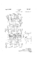
- Fig. 1 is a diagrammatic view illustrating a typical form of conveyer system with which the control mechanism embodying this invention might be employed;
- Fig. 2 is a plan view with parts broken away of one embodiment of the control mechanism
- Fig. 3 is a side elevation of such control mechanism
- Fig. 4 is a cross-sectional view taken along the line 44 of Fig. 2; c
- Fig. 5 is an end elevation of the control mechanism taken from the right;
- Fig. 6 is a plan view of one element of the control mechanism
- Fig. 7 is a side and end elevation of another element of the control mechanism.
- Fig. 8 is a typical diagram 01' the electrical wiring which might be employed in carrying out the invention.
- a barrier I8 normally extends across the main conveyer ID to prevent the travel of articles and is held in such position by a latch mechanism i9, one including a solenoid being here selected.
- the control mechanism A comprises an elongated casing 20 in which travels a slat conveyer 2
- the conveyer slats 24 are provided with a plurality of pockets 25, here shown as apertures, in the present instance five in number, and are carried by chains 26 which pass over the sprockets 22.
- Power may be applied to the left-hand shaft (Fig. 2) through a pulley or gear wheel 21.
- the slats travel over angle supports 28 and are thus held a predetermined distance below the upper plate 29 of the casing 20.
- the pockets 25 are adapted to receive and carry elements, as for example marbles or pellets 30 fed thereto through chutes 31 which lead to openings 32 in the plate 29 over the path of travel of the pockets.
- elements as for example marbles or pellets 30 fed thereto through chutes 31 which lead to openings 32 in the plate 29 over the path of travel of the pockets.
- guiding chan nels 33 Mounted upon the under side of the plate 29 are guiding chan nels 33, the walls: ofwhich extend as shown in;
- rock shafts 36 which extend across the casing and carry a plurality of rocker arms 31 and 38.
- the arms 31 are fixed by set screws 39 to the shafts 36 (see Fig. 7), while the arms 38 turn freely on the shafts between collars 40 (see Fig. 4).
- the shaft 36 of the first housing beginning at the right in Fig. 2, is provided with five rocker arms 31 and mounted in that housing is a I circuit control device It positioned to be tripped by one ofthe arms 31.
- the shafts 36 of the other housings each carry onerocker arm 38 and one or more rocker arms 31, and there is mounted in each housing a circuit control device 42 positioned to be tripped by the rocker arm 38 and a circuit control device 43 positionedto be tripped by a rocker arm
- a circuit control device 42 positioned to be tripped by the rocker arm 38
- a circuit control device 43 positionedto be tripped by a rocker arm
- energizes a solenoid 50 of the barrier latch mechanism i9, each of the circuit makers 42 energizes a solenoid 5
- a normally open switch 53 may be closed to keep the solenoid 50 energized when the barrier I8 is not in use.
- the slat conveyer 2 l of the control mechanism A travels at a definite speed relative to that of the articles transported by the main conveyer, and that the lanes in which the marbles are carried through the casing 20., designated as a, b, c, and d (see Figs. 2 and 8) are assigned to the branch conveyers II, 2, l3 and I4 and control the deflection of articles thereto, while the lane e controls articles which are not to be deflected.
- the operator then drops a marble 30 into that chute 3
- the marble enters the corresponding pocket 25 of a slat 24, is carried thereby along the lane, trips the rocker arm 31 on the shaft 38 in the first housing 35 and causes it to actuate the circuit maker 4
- the marble then trips the rocker arm 38 on the shaft 36 in the second housing andcauses it to actuate the circuit maker 42, thereby energizing the solenoid 59 of the mechanism It, which operates the first deflector I5 and swings it into the operative position in which it is locked by the latch mechanism
- the marble is carried to the end of the casing, dropped into the trough 45 and returned to the operator.
- next article is also to be deflected to the branch conveyer Ii another marble is dropped into the same chute 3
- Mechanism for controlling the travel of articles through a conveyer system which includes a main conveyer, one or more branch conveyers leading therefrom, a deflector at the junction of each branch conveyer with the main conveyer, and means associated with each deflector for determining the position thereof, such mechanism including a barrier normally preventing the travel of articles on the main conveyer, one or more lanes through which elements travel, devices in each lane tripped by the elements traveling therein, and connections between such devices and the barrier and deflector position determining means whereby when the devices in the lanes are tripped the barrier permits the travel of an article and such deflectors are set in the operative positions.
- Mechanism for controlling the travel of articles through a conveyer system which includes a main conveyer, one or more branch conveyers leading therefrom, a deflector at the junction of each branch conveyer with the main conveyer, and means associated with each deflector for determining the position thereof
- such mechanism including a barrier normally preventing the travel of articles on the main conveyer, one or more lanes through which elements travel, mechanism for causing said elements to travel through said lanes at a rate relative to that of the articles on the main conveyer, devices in each lane tripped by the elements traveling therein, and connec-- tions between such devices and the barrier and deflector position, determining means whereby when the devices in the lanes are tripped the barrier permits the travel of an article and such deflectors are set in the operative positions to deflect articles on the main conveyer.
- Mechanism ior controlling the passage of articles through a conveyer system which includes a main conveyer, a plurality of branch conveyers leading therefrom, a deflector at the Junction of each branch conveyer and the main conveyer and means associated with each deflector for determining the position thereof, such mec including a plurality of lanes through which elements travel, each lane being assigned to a particular deflector and to those in advance of that deflector, a slat conveyer for transporting the ele ments through the lanes at a rate relative to'tliat of the articles on the main conveyer, me for feeding an element to a selected lane as an article, destined to the branch conveyer to which articles on the main conveyer are deflected by the particu lar deflector to winch the lane-is assigned, a 3 a certain point, and means actuated by said ele ment as it is transported through the lane for causing the position deter-g means of the particular deflector to set that deflector in the o
- Mechanism for controlling the passage or articles through a conveyer system which includes a main conveyer, a plurality of branch conveyers leading therefrom, a deflector at the junction of each branch conveyer and the main conveyer, and means associated with each deflector for determining the position thereof, such mechanism including lanes through which elements travel, a slat conveyer for transporting the elements through the lanes at a rate relative to that of the articles on the main conveyer, devices in each lane tripped by the elements traveling therein, connections between such devices and the deflector position determining means, one device of each lane being associated with a particular deflector so that when tripped it sets that deflector in the operative position and the other devices 01 each lane being associated with the deflectors in advance of the particular deflector so that when tripped any deflectors in advance which may be in the operative position are set in the inoperative position, and means for feeding an element to any selected lane as an article in transit reaches a predetermined point whereby the deflector associated
- Mechanism for controlling the travel of articles through a conveyer system which includes a main conveyer, a plurality of branch conveyers leading therefrom, a deflector at the junction of each branch conveyer with the main conveyer, means associated with each deflector for moving it into operative position, and means for latching it in such position, such mechanism including a plurality of lanes through which elements travel, mec for causing said elements to travel through said lanes at a rate relative to that of the articles on the main conveyer, two devices in each lane tripped by the elements traveling therein, connections between one of the devices in each lane and said deflector moving means and connections between the other oi the devices in each lane and the deflector latching means whereby the tripping oi the devices in each lane by an element traveling therein will actuate the latch means of one deflector and the moving means of another deflector to deflect articles on the main conveyer to the desired branch conveyer.
- Mechanism for controlling the travel of articles through a conveyer system which includes a main conveyer, a plurality of branch conveyers leading therefrom, a deflector at the junction of each branch conveyer with the main conveyer, means associated with each deflector for moving it into operative position, and means for latching it in such position, such mechanism including a plurality of lanes throimh which elements travel, a slat conveyer for' transporting the elements through the lanes at a rate relative to that of the articles on the main conveyer, two devices in each lane tripped by the elements traveling therein, connections between one of the devices in each lane and said deflector moving means and connections between theother of the devices in each lane and the deflector latching means whereby the tripping of the devices in each lane by an element traveling therein will actuate the latch means of one deflector and the moving means of another deflector to deflect articles on the main conveyer to the desired branch conveyer.
- Mechanism for controlling the travel of articles through a conveyer system which includes a main conveyer, a plurality of branch conveyers leading therefrom, a deflector at the junction of each branch conveyer with the main conveyer, means associated with each deflector for moving it into operative position, and means for latching it in such position, such mechanism includirg a plurality of lanes through which elements travel, a slat conveyer having pockets therein which receive and transport the elements through the lanes, chutes through which the elements are fed into the pockets in said slat conveyer, two devices in each lane tripped by the elements traveling therein, connections between one of the devices in each lane and said deflector, moving means and connections between the other of the devices in each lane and the deflector latching means whereby the tripping of the devices in each lane by an element traveling therein will actuate the latch means of one deflector and the moving means of another deflector.
- Mechanism for controlling the travel of articles through a conveyer system which includes a main conveyer, a plurality of branch conveyers leading therefrom. a deflector at the junction of each branch conveyer and the main conveyer, means associated with each deflector for determining the positions thereof, a barrier which prevents the advance of articles over said main conveyer toward said deflectors, and means for holding said barrier in the article preventing position, such mechanism comprising means for rendering said barrier ineffective and thus permitting the advance of an article, devices connected with the deflector position determining means, and means for actuating said barrier rendering means and the device connected with the deflector at the junction of a selected branch conveyer whereby that deflector is in the position to deflect the advancing article into its branch conveyer.
- Mechanism for controlling the travel of articles through a conveyer system which includes a main conveyer, a plurality of branch conveyers leading therefrom, a deflector at the junction of each branch conveyer and the main conveyer, means associated with each deflector for determining the positions thereof, a barrier which prevents the advance of articles over said main conveyer toward said deflectors, and means for holdixm said barrier in the article preventing position, such mechanism comprising means for rendering said barrier ineifective and thus permitting the advance of an article, devices connected with the deflector position determining means, and means for actuating said barrier rendering means and the device connected with the deflector at the junction of a selected branch conveyer whereby that deflector is in the position to deflect the advancing article into its branch conveyer, said last-named means including a plurality of lanes through which elements may travel, arms extending into said lanes to be tripped by said elements, which arms when tripped actuate said barrier rendering means, and means for advancing an element through a selected lane.
- Mechanism for controlling thetravel of articles through a conveyer system which includes a main conveyer, a plurality of branch conveyers leading therefrom, a deflector at the junction of each branch conveyer and the main conveyer, means associated with each deflector for determining the positions thereof, a barrier which prevents the advance of articles over said main conveyer toward said deflectors, and means for holding said barrier in the article preventing position, such mechanism comprising means for rendering said barrier ineffective and thus permitting the advance of an article, devices connected with the deflector position determining means, and means for actuating said barrier rendering means and the device connected with the deflector at the junction of a selected branch conveyer whereby that deflector is in the position to deflect the advancing article into its branch conveyer, said last-named means including a plurality of lanes through which said elements may travel, arms extending into said lanes to be tripped by said elements, which arms when tripped actuate said barrier rendering means and said devices, and means for advancing an element through a selected lane.
- Mechanism for controlling the passage of articles through a conveyer system which includes a main conveyer, a plurality of branch conveyers leading therefrom, a deflector at the junction of each branch conveyer and the main conveyer. and means associated with each deflector for determining the positions thereof, such mechanism comprising operator controlled means including a single actuator for determining the position of the deflectors of a selected branchconveyer and 13.
- Mechanism for controlling the passage of articles through a conveyer system which includes a main conveyer, a plurality of branch conveyers leading therefrom, a deflector at the junction of each branch conveyer and the main conveyer, and means associated with each deflector for determining the positions thereof, such mechanism comprising devices connected with the position determining means of each deflector, and operator controlled means including a single actuator for actuating the positioning determining means of such devices whereby the deflector of a selected branch conveyer is set in the op erative position and the deflector of each branch conveyer in advance of the selected branch conveyer is set in the inoperative position and an article traveling on the main conveyer is de: flected to such selected branch conveyer.
- Mechanism for controlling-the passage of articles through a conveyer system which includes a main conveyer, a plurality of branch conveyers leading therefrom, a deflector at the junction of each branch conveyer and the main conveyer, and means associated with each deflector for determining the positions thereof, such mechanism comprising a plurality of lanes through which elements travel, means for moving the elements through the lanes, each lane being assigned to a particular branch conveyer, devices in each lane connected with the position determining means of the deflector of the branch conveyer assigned to that lane and of the deflector of each branch conveyer in advance of the assigned branch conveyer, and operator controlled means for supplying an element to a selected lane, which element actuates the devices in the lane to set the deflector of the assigned branch conveyer in the opera tive position and the deflector of each branch conveyer in advance thereof in the inoperative position, whereby an article traveling on the main conveyer is deflected to the branch conveyer'as' signed to such selected lane.
- Mechanism for controlling the passage of articles through a conveyer system which includes a main conveyer, a plurality of branch conveyers leading therefrom, a deflector at the junction of each branch conveyer and the main conveyer, and means associated with each deflector for determining the positions thereof, such mechanism comprising a. plurality of lanes through which elements travel, means for moving the elements through the lanes, each lane being assigned to a particular branch conveyer, devices in each lane connected with the position determining means of the deflector of the branch con-.
- Mechanism for controlling the passage of articles through a conveyer system which includes a main conveyer, a plurality of branch conveyers leading therefrom, a normally inoperative deflector at the junction of each branch conveyer and the main conveyer, means associated with each deflector to move it into the operative position in which an article in transit is deflected from the main conveyer to a branch conveyer, and means associated with each deflector to latch and maintain it in its operative position
- operator controlled means including a single actuator for actuating the moving means of the deflector of a selected branch conveyer and ior rendering inoperative the latching means of the deflector of each branch conveyer in advance of the selected branch conveyer to release such as may be in the operative position so that an article in transit on the main conveyer passes undisturbed to the deflector of such selected branch conveyer, and is deflected thereby to that branch conveyer.
- Mechanism for controlling the passage of articles through a conveyer system which includes a main conveyer, a plurality of branch conveyers leading therefrom, a normally inoperative deflector at the junction of each branch conveyer and the main conveyer, means associated with each deflector to move it into the operative position in which an article in transit is deflected from the main conveyer to a branch conveyer, and means associated with each deflector to latch and maintain it in its operative position, such mechanism comprising devices connected with the moving means and the latching means of each deflector,
- Mechanism for controlling the passage of articles through a conveyer system which includes a main conveyer, a plurality of branch conveyers leading therefrom, a normally inoperative deflector at the junction of each branch conveyer and the main conveyer, means associated with each deflector to move it into the operative position, and means associated with-each deflector to latch it in its operative position, such mechanism comprising a plurality of lanes through which elements travel, means for moving the elements through the lanes, each lane being assigned to a particular branch conveyer, devices in each lane connected with the moving means of the deflector of the branch conveyer assigned to that lane, and with the latching means of the deflector of each branch conveyer in advance of the assigned branch conveyer, and operator controlled means for supplying an element to a selected lane, which element actuates the devices in the lane to set the deflector of the assigned branch conveyer in the operative position and render inoperative the latching means of the deflector of each branch conveyer in advance of the assigned branch conveyer whereby an article
Landscapes
- Engineering & Computer Science (AREA)
- Mechanical Engineering (AREA)
- Branching, Merging, And Special Transfer Between Conveyors (AREA)
- Control Of Conveyors (AREA)
- Discharge Of Articles From Conveyors (AREA)
Description
Au. 2Q, 1935. J. E. REGAN 2,011,827
CONVEYER Filed Sept. 27, 1952 4 Sheets-Sheet 1 2 Q Q Q Q' 3.111 24 G Q 0 o 0 Q Q Q Q Q 4 Sheets-Sheet 2 i l l .1
J. E. REGAN Filed Sept. 2'7, 1932 Aug. 20, 1935.-
J. E. REGAN Aug, 20 i935 CONVEYE R 4 Sheets-Sheet 3 Filed Sept. 27, 1952 i O l Aug. 20, 1935. J, E REGAN 2,011,827
CONVEYER Filed Sept. 27, 1932 4 Sheets-Sheet 4 Q N M '1 g I J W1 a l I 1 fnv zzwf Jakrz Z: a172,
Patented Aug. 20, 1935 PATENT OFFICE CONVEYER John E. Regan, Syracuse, N. Y., assignor to The Lamson Company, Syracuse, N. Y., a corporation of Massachusetts Application September 27, 1932, Serial No. 635,035
18 Claims.
This invention relates to an improvement in conveyers and more particularly in a conveyer system including a plurality of deflectors or other direction determining devices.
In systems of this type it is desirable to provide means under the control of an operator by which the course of travel of each article is determined independent of the size, shape or character of the articles. One such means is disclosed in the patent to Spooner, No. 1,528,227, dated March 3, 1925, and the present invention is a further development of the subject matter disclosed therein.
The primary object of this invention resides in the provision. of a mechanism under the control of the operator and comprising a plurality of chutes each adapted to receive an element such as a marble or pellet and a plurality of trips each of which automatically actuates a selected defiector or direction determining device, each trip being associated with a particular chute and being engaged by the element received thereby. Preferably, as will be hereinafter disclosed, the marbles or pellets received in the chutes are advanced into engagement with the trips at a predetermined rate of speed, as, for example, by a slat conveyer.
A further object of this invention resides in the provision of means actuated by the deflector control mechanism for permitting the advance of the selected article in timed relation to that marble or pellet by which the'course of travel of the article is determined.
Other objects will appear from a consideration of the following description of one embodiment of the invention and of the accompanying drawings which illustrate one embodiment of the invention and in which;
Fig. 1 is a diagrammatic view illustrating a typical form of conveyer system with which the control mechanism embodying this invention might be employed;
Fig. 2 is a plan view with parts broken away of one embodiment of the control mechanism;
Fig. 3 is a side elevation of such control mechanism;
Fig. 4 is a cross-sectional view taken along the line 44 of Fig. 2; c
Fig. 5 is an end elevation of the control mechanism taken from the right;
Fig. 6 is a plan view of one element of the control mechanism;
Fig. 7 is a side and end elevation of another element of the control mechanism; and
Fig. 8 is a typical diagram 01' the electrical wiring which might be employed in carrying out the invention.
The selected conveyer system shown in Fig. 1:
is of a well-known type comprising a main conveyer I0 and a plurality of branch conveyers H, H, I3 and M to which articles transported by the main conveyer are deflected by deflectors I5. Each deflector is advanced from the normal inoperative position shown in dotted lines to the operative position shown in full lines by mechanism designated generally by the numerals l6, each of which includes as an operating element a solenoid, and is held in such operative position by a latch H, which is retracted by a solenoid not shown. A barrier I8 normally extends across the main conveyer ID to prevent the travel of articles and is held in such position by a latch mechanism i9, one including a solenoid being here selected. These solenoids are indicated diagrammatically in the wiring diagram of Fig. 8. Adjajacent the barrier I8 is located the control mechanism A by which, as will be set forth below, the destination of each article traveling on the conveyer i0 is selectively determined by an operator.
The control mechanism A comprises an elongated casing 20 in which travels a slat conveyer 2| over end sprockets 22 carried on shafts 23. The conveyer slats 24 are provided with a plurality of pockets 25, here shown as apertures, in the present instance five in number, and are carried by chains 26 which pass over the sprockets 22. Power may be applied to the left-hand shaft (Fig. 2) through a pulley or gear wheel 21. At the upper reach or run of the conveyer the slats travel over angle supports 28 and are thus held a predetermined distance below the upper plate 29 of the casing 20. The pockets 25 are adapted to receive and carry elements, as for example marbles or pellets 30 fed thereto through chutes 31 which lead to openings 32 in the plate 29 over the path of travel of the pockets. Mounted upon the under side of the plate 29 are guiding chan nels 33, the walls: ofwhich extend as shown in;
Fig. 4 at the sides of the marbles in the pockets and prevent their escape laterally therefrom.
Mounted in housings 35 supported on the casing 20 are rock shafts 36, which extend across the casing and carry a plurality of rocker arms 31 and 38. The arms 31 are fixed by set screws 39 to the shafts 36 (see Fig. 7), while the arms 38 turn freely on the shafts between collars 40 (see Fig. 4). The shaft 36 of the first housing, beginning at the right in Fig. 2, is provided with five rocker arms 31 and mounted in that housing is a I circuit control device It positioned to be tripped by one ofthe arms 31. The shafts 36 of the other housings each carry onerocker arm 38 and one or more rocker arms 31, and there is mounted in each housing a circuit control device 42 positioned to be tripped by the rocker arm 38 and a circuit control device 43 positionedto be tripped by a rocker arm When the marbles transported by the slat conveyer 2| arrive at the end of the upper reach they fall out of the pockets 25 into a trough 45, which is so inclined that the marbles are returned by gravity through a pipe 48 into a trough 41 from which they can easily be removed by the operator. In the typical wiring diagram shown in Fig. 8 the circuit control devices 4|, 42 and 43 are all normally open circuit makers. The circuit maker 4|, energizes a solenoid 50 of the barrier latch mechanism i9, each of the circuit makers 42 energizes a solenoid 5| of a deflector operating mechanism I6 and each of the circuit makers 43 energizes a solenoid 52, which retracts a deflector latch IT. ,A normally open switch 53 may be closed to keep the solenoid 50 energized when the barrier I8 is not in use. The circuits set up when the various circuit breakers are tripped will not be described in detail, since they are obvious from a consideration of the diagram in connection with the following description of the operation.
In this description of the operation of this system, it will be understood that the slat conveyer 2 l of the control mechanism A travels at a definite speed relative to that of the articles transported by the main conveyer, and that the lanes in which the marbles are carried through the casing 20., designated as a, b, c, and d (see Figs. 2 and 8) are assigned to the branch conveyers II, 2, l3 and I4 and control the deflection of articles thereto, while the lane e controls articles which are not to be deflected. T 4
Assume that the barrier i8 is latched in position across the main conveyer and that an article to be deflected to the branch conveyer I l is at the barrier, the operator then drops a marble 30 into that chute 3| at the right end in Fig. 5 leading to lane a. The marble enters the corresponding pocket 25 of a slat 24, is carried thereby along the lane, trips the rocker arm 31 on the shaft 38 in the first housing 35 and causes it to actuate the circuit maker 4|, thereby energizing the solenoid 50 of the latch mechanism l9, which releases the barrier I8 and allows the article to advance. The marble then trips the rocker arm 38 on the shaft 36 in the second housing andcauses it to actuate the circuit maker 42, thereby energizing the solenoid 59 of the mechanism It, which operates the first deflector I5 and swings it into the operative position in which it is locked by the latch mechanism |1 so that the article will be deflected onto the branch conveyer The marble is carried to the end of the casing, dropped into the trough 45 and returned to the operator. If the next article is also to be deflected to the branch conveyer Ii another marble is dropped into the same chute 3|, but that marble merely acts to release the barrier, and its tripping of the arm 38 performs no function because the deflector l5 at that conveyer is held in the operative position by the latch mechanism l1. When, however, an article arrives'at the barrier to be deflected to another branch conveyer, for example conveyer M, the marble is dropped into the chute 3| feeding the lane d, and as that marble passes along the casing it trips, not only the rocker arm 31 of the first housing torelease the barrier, but also the arms 31 of the second, third and fourth housings actuating the latch mechanisms of the deflectors at conveyers I, I2 and I3 through circuit makers 4| and solenoids 52, and thus clearing the way for the article on the main conveyer. At the fifth housing it trips the rocker arm 38 which, through the circuit maker 42 and solenoid 5|, causes the mechanism I6 to close the deflector |5 at the desired branch conveyer. Should the article be one to pass all the branch conveyers, a marble is dropped through the chute 3|, which conducts it to lane e and the marble traveling through that lane trips a rocker arm 31 in each housing, thus releasing the barrier l8 and each of the deflectors I5.
Since there is only one rocker arm 38 in any housing they are mounted to swing freely upon their shafts. The rocker arms 31, however, are all fixed on the shafts and hence the tripping of any rocker arm in a housing causes the actuation of the circuit breaker 43 in such housing. It will be noted that the marbles traveling in each lane act not only to release the barrier and actuate the deflector of the desired branch conveyer but also to render the deflectors of the intermediate branch conveyers inoperative, thus clearing the way for the articles and insuring their uninterrupted travel to the proper branch conveyer or past all the branch conveyers.
When the switch 53 is closed the barrier I. remains open and under these conditions it is only necessary to drop a marble into the control mechanism when the destination of an article differs from that of the preceding article.
While one embodiment of this invention has been shown and described in detail it will be understood that I am not limited thereto and that other embodiments thereof may be made without departing from the spirit and scope of the invention as set forth in the following claims.
I claim:
1. Mechanism for controlling the travel of articles through a conveyer system which includes a main conveyer, one or more branch conveyers leading therefrom, a deflector at the junction of each branch conveyer with the main conveyer, and means associated with each deflector for determining the position thereof, such mechanism including a barrier normally preventing the travel of articles on the main conveyer, one or more lanes through which elements travel, devices in each lane tripped by the elements traveling therein, and connections between such devices and the barrier and deflector position determining means whereby when the devices in the lanes are tripped the barrier permits the travel of an article and such deflectors are set in the operative positions.
2. Mechanism for controlling the travel of articles through a conveyer system which includes a main conveyer, one or more branch conveyers leading therefrom, a deflector at the junction of each branch conveyer with the main conveyer, and means associated with each deflector for determining the position thereof such mechanism including a barrier normally preventing the travel of articles on the main conveyer, one or more lanes through which elements travel, mechanism for causing said elements to travel through said lanes at a rate relative to that of the articles on the main conveyer, devices in each lane tripped by the elements traveling therein, and connec-- tions between such devices and the barrier and deflector position, determining means whereby when the devices in the lanes are tripped the barrier permits the travel of an article and such deflectors are set in the operative positions to deflect articles on the main conveyer.
3. Mechanism ior controlling the passage of articles through a conveyer system which includes a main conveyer, a plurality of branch conveyers leading therefrom, a deflector at the Junction of each branch conveyer and the main conveyer and means associated with each deflector for determining the position thereof, such mec including a plurality of lanes through which elements travel, each lane being assigned to a particular deflector and to those in advance of that deflector, a slat conveyer for transporting the ele ments through the lanes at a rate relative to'tliat of the articles on the main conveyer, me for feeding an element to a selected lane as an article, destined to the branch conveyer to which articles on the main conveyer are deflected by the particu lar deflector to winch the lane-is assigned, a 3 a certain point, and means actuated by said ele ment as it is transported through the lane for causing the position deter-g means of the particular deflector to set that deflector in the op erative position and causing the position deter mining means of the advance deflectors to set in the inoperative position any of such advance deflectors as may at that time be in the operative position whereby the article travels along the main conveyer to the particular deflector by which it is deflected undisturbed by any advance deflector.
4. Mechanism for controlling the passage or articles through a conveyer system which includes a main conveyer, a plurality of branch conveyers leading therefrom, a deflector at the junction of each branch conveyer and the main conveyer, and means associated with each deflector for determining the position thereof, such mechanism including lanes through which elements travel, a slat conveyer for transporting the elements through the lanes at a rate relative to that of the articles on the main conveyer, devices in each lane tripped by the elements traveling therein, connections between such devices and the deflector position determining means, one device of each lane being associated with a particular deflector so that when tripped it sets that deflector in the operative position and the other devices 01 each lane being associated with the deflectors in advance of the particular deflector so that when tripped any deflectors in advance which may be in the operative position are set in the inoperative position, and means for feeding an element to any selected lane as an article in transit reaches a predetermined point whereby the deflector associated therewith is set in the operative position and the deflectors in advance of that deflector are in the inoperative position and the article travels undisdisturbed until deflected by the deflector associated with that lane.
' traveling therein, connections between one of the devices in each lane and said deflector moving means and connections between the other of the devices in each lane and the deflector latching means whereby the tripping of the devices in each lane by an element traveling therein will actuate the latch means of one deflector and the moving means of another deflector.
8. Mechanism for controlling the travel of articles through a conveyer system which includes a main conveyer, a plurality of branch conveyers leading therefrom, a deflector at the junction of each branch conveyer with the main conveyer, means associated with each deflector for moving it into operative position, and means for latching it in such position, such mechanism including a plurality of lanes through which elements travel, mec for causing said elements to travel through said lanes at a rate relative to that of the articles on the main conveyer, two devices in each lane tripped by the elements traveling therein, connections between one of the devices in each lane and said deflector moving means and connections between the other oi the devices in each lane and the deflector latching means whereby the tripping oi the devices in each lane by an element traveling therein will actuate the latch means of one deflector and the moving means of another deflector to deflect articles on the main conveyer to the desired branch conveyer.
7. Mechanism for controlling the travel of articles through a conveyer system which includes a main conveyer, a plurality of branch conveyers leading therefrom, a deflector at the junction of each branch conveyer with the main conveyer, means associated with each deflector for moving it into operative position, and means for latching it in such position, such mechanism including a plurality of lanes throimh which elements travel, a slat conveyer for' transporting the elements through the lanes at a rate relative to that of the articles on the main conveyer, two devices in each lane tripped by the elements traveling therein, connections between one of the devices in each lane and said deflector moving means and connections between theother of the devices in each lane and the deflector latching means whereby the tripping of the devices in each lane by an element traveling therein will actuate the latch means of one deflector and the moving means of another deflector to deflect articles on the main conveyer to the desired branch conveyer.
8. Mechanism for controlling the travel of articles through a conveyer system which includes a main conveyer, a plurality of branch conveyers leading therefrom, a deflector at the junction of each branch conveyer with the main conveyer, means associated with each deflector for moving it into operative position, and means for latching it in such position, such mechanism includirg a plurality of lanes through which elements travel, a slat conveyer having pockets therein which receive and transport the elements through the lanes, chutes through which the elements are fed into the pockets in said slat conveyer, two devices in each lane tripped by the elements traveling therein, connections between one of the devices in each lane and said deflector, moving means and connections between the other of the devices in each lane and the deflector latching means whereby the tripping of the devices in each lane by an element traveling therein will actuate the latch means of one deflector and the moving means of another deflector.
9. Mechanism for controlling the travel of articles through a conveyer system which includes a main conveyer, a plurality of branch conveyers leading therefrom. a deflector at the junction of each branch conveyer and the main conveyer, means associated with each deflector for determining the positions thereof, a barrier which prevents the advance of articles over said main conveyer toward said deflectors, and means for holding said barrier in the article preventing position, such mechanism comprising means for rendering said barrier ineffective and thus permitting the advance of an article, devices connected with the deflector position determining means, and means for actuating said barrier rendering means and the device connected with the deflector at the junction of a selected branch conveyer whereby that deflector is in the position to deflect the advancing article into its branch conveyer.
10. Mechanism for controlling the travel of articles through a conveyer system which includes a main conveyer, a plurality of branch conveyers leading therefrom, a deflector at the junction of each branch conveyer and the main conveyer, means associated with each deflector for determining the positions thereof, a barrier which prevents the advance of articles over said main conveyer toward said deflectors, and means for holdixm said barrier in the article preventing position, such mechanism comprising means for rendering said barrier ineifective and thus permitting the advance of an article, devices connected with the deflector position determining means, and means for actuating said barrier rendering means and the device connected with the deflector at the junction of a selected branch conveyer whereby that deflector is in the position to deflect the advancing article into its branch conveyer, said last-named means including a plurality of lanes through which elements may travel, arms extending into said lanes to be tripped by said elements, which arms when tripped actuate said barrier rendering means, and means for advancing an element through a selected lane.
11. Mechanism for controlling thetravel of articles through a conveyer system which includes a main conveyer, a plurality of branch conveyers leading therefrom, a deflector at the junction of each branch conveyer and the main conveyer, means associated with each deflector for determining the positions thereof, a barrier which prevents the advance of articles over said main conveyer toward said deflectors, and means for holding said barrier in the article preventing position, such mechanism comprising means for rendering said barrier ineffective and thus permitting the advance of an article, devices connected with the deflector position determining means, and means for actuating said barrier rendering means and the device connected with the deflector at the junction of a selected branch conveyer whereby that deflector is in the position to deflect the advancing article into its branch conveyer, said last-named means including a plurality of lanes through which said elements may travel, arms extending into said lanes to be tripped by said elements, which arms when tripped actuate said barrier rendering means and said devices, and means for advancing an element through a selected lane.
12. Mechanism for controlling the passage of articles through a conveyer system which includes a main conveyer, a plurality of branch conveyers leading therefrom, a deflector at the junction of each branch conveyer and the main conveyer. and means associated with each deflector for determining the positions thereof, such mechanism comprising operator controlled means including a single actuator for determining the position of the deflectors of a selected branchconveyer and 13. Mechanism for controlling the passage of articles through a conveyer system which includes a main conveyer, a plurality of branch conveyers leading therefrom, a deflector at the junction of each branch conveyer and the main conveyer, and means associated with each deflector for determining the positions thereof, such mechanism comprising devices connected with the position determining means of each deflector, and operator controlled means including a single actuator for actuating the positioning determining means of such devices whereby the deflector of a selected branch conveyer is set in the op erative position and the deflector of each branch conveyer in advance of the selected branch conveyer is set in the inoperative position and an article traveling on the main conveyer is de: flected to such selected branch conveyer.
14. Mechanism for controlling-the passage of articles through a conveyer system which includes a main conveyer, a plurality of branch conveyers leading therefrom, a deflector at the junction of each branch conveyer and the main conveyer, and means associated with each deflector for determining the positions thereof, such mechanism comprising a plurality of lanes through which elements travel, means for moving the elements through the lanes, each lane being assigned to a particular branch conveyer, devices in each lane connected with the position determining means of the deflector of the branch conveyer assigned to that lane and of the deflector of each branch conveyer in advance of the assigned branch conveyer, and operator controlled means for supplying an element to a selected lane, which element actuates the devices in the lane to set the deflector of the assigned branch conveyer in the opera tive position and the deflector of each branch conveyer in advance thereof in the inoperative position, whereby an article traveling on the main conveyer is deflected to the branch conveyer'as' signed to such selected lane.
15. Mechanism for controlling the passage of articles through a conveyer system which includes a main conveyer, a plurality of branch conveyers leading therefrom, a deflector at the junction of each branch conveyer and the main conveyer, and means associated with each deflector for determining the positions thereof, such mechanism comprising a. plurality of lanes through which elements travel, means for moving the elements through the lanes, each lane being assigned to a particular branch conveyer, devices in each lane connected with the position determining means of the deflector of the branch con-. veyer assigned to that lane'and of the deflector of each branch conveyer in advance of the assigned branch conveyer, and operator controlled means for supplying an element to a selected lane, which element actuates the devices in the lane to set the deflector of the assigned branch conveyer in the operative position and the deflector of each branch conveyer in advance thereof in the inoperative position, whereby an article traveling on the main conveyer is deflected to the branch conveyer assignedto such selected lane, a lane assigned to none of the branch conveyers and devices in said lane connected with the position determining of each of the deflectors, which devices are actuated by an element supplied to that lane to set all the deflectors in the inoperative position, whereby an article traveling on the main conveyer is not deflected to any of the branch conveyers.
16. Mechanism for controlling the passage of articles through a conveyer system which includes a main conveyer, a plurality of branch conveyers leading therefrom, a normally inoperative deflector at the junction of each branch conveyer and the main conveyer, means associated with each deflector to move it into the operative position in which an article in transit is deflected from the main conveyer to a branch conveyer, and means associated with each deflector to latch and maintain it in its operative position, such mechanism comprising operator controlled means including a single actuator for actuating the moving means of the deflector of a selected branch conveyer and ior rendering inoperative the latching means of the deflector of each branch conveyer in advance of the selected branch conveyer to release such as may be in the operative position so that an article in transit on the main conveyer passes undisturbed to the deflector of such selected branch conveyer, and is deflected thereby to that branch conveyer.
17. Mechanism for controlling the passage of articles through a conveyer system which includes a main conveyer, a plurality of branch conveyers leading therefrom, a normally inoperative deflector at the junction of each branch conveyer and the main conveyer, means associated with each deflector to move it into the operative position in which an article in transit is deflected from the main conveyer to a branch conveyer, and means associated with each deflector to latch and maintain it in its operative position, such mechanism comprising devices connected with the moving means and the latching means of each deflector,
and operator controlled means including a single actuator for actuating the device connected with the moving means of the deflector of a selected branch conveyer to set it in the operative position and for actuating each device connected with the latching means of the deflector of each branch conveyer in advance of the selected branch con-' veyer to render it inoperative and release such deflector or deflectors as may be in the operative position so that an article in transit on the main conveyer passes undisturbed to the deflector of .such branch conveyer, and is deflected thereby to that branch conveyer. v
18. Mechanism for controlling the passage of articles through a conveyer system which includes a main conveyer, a plurality of branch conveyers leading therefrom, a normally inoperative deflector at the junction of each branch conveyer and the main conveyer, means associated with each deflector to move it into the operative position, and means associated with-each deflector to latch it in its operative position, such mechanism comprising a plurality of lanes through which elements travel, means for moving the elements through the lanes, each lane being assigned to a particular branch conveyer, devices in each lane connected with the moving means of the deflector of the branch conveyer assigned to that lane, and with the latching means of the deflector of each branch conveyer in advance of the assigned branch conveyer, and operator controlled means for supplying an element to a selected lane, which element actuates the devices in the lane to set the deflector of the assigned branch conveyer in the operative position and render inoperative the latching means of the deflector of each branch conveyer in advance of the assigned branch conveyer whereby an article traveling on the main conveyer is deflected to the branch conveyer assigned to such lane.- t
JOHN E. REGAN.
Priority Applications (1)
| Application Number | Priority Date | Filing Date | Title |
|---|---|---|---|
| US635035A US2011827A (en) | 1932-09-27 | 1932-09-27 | Conveyer |
Applications Claiming Priority (1)
| Application Number | Priority Date | Filing Date | Title |
|---|---|---|---|
| US635035A US2011827A (en) | 1932-09-27 | 1932-09-27 | Conveyer |
Publications (1)
| Publication Number | Publication Date |
|---|---|
| US2011827A true US2011827A (en) | 1935-08-20 |
Family
ID=24546164
Family Applications (1)
| Application Number | Title | Priority Date | Filing Date |
|---|---|---|---|
| US635035A Expired - Lifetime US2011827A (en) | 1932-09-27 | 1932-09-27 | Conveyer |
Country Status (1)
| Country | Link |
|---|---|
| US (1) | US2011827A (en) |
Cited By (6)
| Publication number | Priority date | Publication date | Assignee | Title |
|---|---|---|---|---|
| US2610748A (en) * | 1939-04-11 | 1952-09-16 | Larham David Percival | Machine for sorting goods |
| US2636622A (en) * | 1947-08-18 | 1953-04-28 | Conveyor Company | Automatic car loading conveyer system |
| US2666535A (en) * | 1949-08-20 | 1954-01-19 | Jordan Marsh Company | Sorting system |
| US2898452A (en) * | 1954-12-13 | 1959-08-04 | Roland J Berti | Switching systems and apparatus therefor |
| US3263776A (en) * | 1965-01-08 | 1966-08-02 | Jr Robert H Kroemer | Food service system |
| US3424320A (en) * | 1965-05-26 | 1969-01-28 | Electrolux Ab | Conveyor system |
-
1932
- 1932-09-27 US US635035A patent/US2011827A/en not_active Expired - Lifetime
Cited By (6)
| Publication number | Priority date | Publication date | Assignee | Title |
|---|---|---|---|---|
| US2610748A (en) * | 1939-04-11 | 1952-09-16 | Larham David Percival | Machine for sorting goods |
| US2636622A (en) * | 1947-08-18 | 1953-04-28 | Conveyor Company | Automatic car loading conveyer system |
| US2666535A (en) * | 1949-08-20 | 1954-01-19 | Jordan Marsh Company | Sorting system |
| US2898452A (en) * | 1954-12-13 | 1959-08-04 | Roland J Berti | Switching systems and apparatus therefor |
| US3263776A (en) * | 1965-01-08 | 1966-08-02 | Jr Robert H Kroemer | Food service system |
| US3424320A (en) * | 1965-05-26 | 1969-01-28 | Electrolux Ab | Conveyor system |
Similar Documents
| Publication | Publication Date | Title |
|---|---|---|
| US1868894A (en) | Conveyer | |
| US2011827A (en) | Conveyer | |
| US3523618A (en) | Feeder devices | |
| PL81147B1 (en) | ||
| US2886164A (en) | Conveyors | |
| US2298829A (en) | Conveyer system | |
| US1939891A (en) | Conveyer system | |
| US2455741A (en) | Automatic can distributor | |
| US2797057A (en) | Pneumatic dispatch-tube systems | |
| US3265901A (en) | Electronic bottle width selector | |
| US1781424A (en) | Conveying and spacing apparatus | |
| US3036689A (en) | Conveyor system for supplying articles of a plurality of kinds to apparatus for assembling them | |
| US1825038A (en) | Conveying apparatus | |
| US1895046A (en) | Conveyer mechanism | |
| US1938104A (en) | Conveyer system | |
| US1563446A (en) | Package sorter | |
| US1968547A (en) | Conveying system | |
| US1620531A (en) | Apparatus for loading and unloading materials | |
| US1820674A (en) | Safety shut-off device for conveyer systems | |
| US2346285A (en) | Conveyer system | |
| US1990050A (en) | Conveying mechanism | |
| US2372789A (en) | Conveyer system | |
| US1655476A (en) | Conveyer system | |
| US1923447A (en) | Conveyer mechanism | |
| US2357875A (en) | Conveyer system |