US2011826A - Apparatus for handling multiple paper strips - Google Patents
Apparatus for handling multiple paper strips Download PDFInfo
- Publication number
- US2011826A US2011826A US687631A US68763133A US2011826A US 2011826 A US2011826 A US 2011826A US 687631 A US687631 A US 687631A US 68763133 A US68763133 A US 68763133A US 2011826 A US2011826 A US 2011826A
- Authority
- US
- United States
- Prior art keywords
- paper
- plate
- strips
- carbon
- sheets
- Prior art date
- Legal status (The legal status is an assumption and is not a legal conclusion. Google has not performed a legal analysis and makes no representation as to the accuracy of the status listed.)
- Expired - Lifetime
Links
Images


Classifications
-
- B—PERFORMING OPERATIONS; TRANSPORTING
- B41—PRINTING; LINING MACHINES; TYPEWRITERS; STAMPS
- B41J—TYPEWRITERS; SELECTIVE PRINTING MECHANISMS, i.e. MECHANISMS PRINTING OTHERWISE THAN FROM A FORME; CORRECTION OF TYPOGRAPHICAL ERRORS
- B41J17/00—Mechanisms for manipulating page-width impression-transfer material, e.g. carbon paper
Definitions
- This invention relates to improvements in means for supporting, aligning and guiding a plurality of superimposed strips of paper, and means for supportin g in interleaved relationship with E6 the strips of paper, sheets of carbon paper, and
- the invention has for its object the provision, in connection with an apparatus for supporting iii) a plurality of strips of paper, means for adjust ably supporting a plurality of sheets of carbon paper interleaved between the strips of paper.
- the type may strike upon that part of the carbon sheets between lines formerly used.
- Figure 1 is a perspective view showing the upper part of a typewriter, with the apparatus attached thereto.
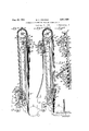
- Figure 2 shows fragments of the superimposed strips of paper with the interleaved carbon sheets therebetween and the supports for the carbon sheets.
- Figure 4 is a section side bars.
- Figure5 is a section similar to Figure 4 but showing the position of the strips of paper-and 5 the carbon sheets at the end of the writing operation.
- Figure 6 is a view showing one end of the aligning mechanism, together with the chain to which it is attached and the strips of paper aligned 10 thereby.
- Figure 7 is a vertical sectional view of the aligning mechanism, with the aligning pins released from the holes in the paper strips.
- Figure 8 is a section similar to Figure 4 but 15.
- FIG. 9 is a view showing thelower ends'oi the strips of paper and the carbon sheets with perforations therein, by which the sheets are 20 divided into narrow strips which may be easily torn oiT.
- Figure 10 is a section on the line ifl-lfi of Figure 3.
- Figure 11 is a view showing the spring attached as to one of the sprocket chain shafts. This view shows the spring casing in section.
- Figure 12 shows the front face of the carbon supporting plate, with means thereon for adjusting the position of the carbon sheets with re- 30 lation to the plate.
- Figure 13 shows the back face of the carbon supporting plate, with means thereon for adjustably supporting the plate on the supporting chain.
- Figure 14 shows the carbon sheets supported 35 in their lower position on the carbon supporting plate
- a guide plate II On the upper end of the frame and attached to the side bars is a guide plate II.
- This plate is attached to the side bars by means of rivets l8, and has adjacent each 'end thereof a slot l9 adapted to receive one end of a guide pin 20, adjustably supported in the slot by means of a screw 2
- a carbon supporting plate 24 Supported on the front of the frame and by the side bars thereof, is a carbon supporting plate 24.
- This plate engages the side bars at each end, and has struck up therefrom tongues 25, which fit behind part of the side bars for guiding the plate as it moves up. and down on the .frame.
- the frame is U-shaped, with the arms thereof projecting toward-each other, and it is the front arms of these side bars that are engaged by the carbon supporting plate and thetongues struck up therefrom.
- This plate is adjlistably attached to the chains 82 by means of pins 26.
- pins 26 There are two of these pins, one attached to each end of a flat spring 27, attached intermediate its ends to the plate by means of rivets 28 (Figure 10).
- the plate is provided with holes 2611 to receive the free ends of these pins.
- These pins pass through links of the chains for supporting the plate on the chains.
- Each pin is supported at one end by the flat spring, while its other end is supported by the plate when the plate is supported on the chains.
- the chains are held in close engagement with the plate by.
- loops 29 In the present instance there are two loops for each end of the flat spring. These loops prevent the chain from pulling the pins out of the'holes so there is no danger of the carbon supporting plate being accidentally released from Adjacent each end of the plate 24 is a U- shaped slot 30 ( Figures 12 and 13).
- the arms are two of these pins, one attached to each end of a flat spring 27, attached intermediate its ends to the plate by means
- which has attached to each end a pin am.
- the parts of these pins on one side of the spring strip are adapted to support a plurality of sheets of carbon paper interleaved between strips of paper, while the parts of the pins projecting on the other side of the spring strip serve 'to engage the plate 24 within the slots 30 to hold the spring strip in the slots in adjusted position with relation to the plate.
- the carbon paper can be so adjusted as to cause the type to strike the portion of the unused carbon sheets between the lines previously struck.
- the parts of the pins projecting through the slots are indicated by the These pins may be.
- washers 33 serve to hold the pins and the spring strip against the plate, but permit a free movement in relation thereto.
- the pins 3la. have thereon a plurality of circular notches 34 adapted to receive a member, not shown, for holding the carbon sheets on the pins. also provided with small pins 35 to prevent the carbon sheets from slipping off of the pins 3
- a paper feed plate 36 which is attached to the sprocket chains I 2, as by the bolts 36a.
- the feed plate 36' has at each end, on the upper edge thereof, a bracket 31 ( Figures 4 to 8 inclusive). These brackets support a guide rod 38 by means of screws 39 extending through the brackets into the ends of the rod.
- a guiding disc 40 adjusted with relation to the rod by means of a set screw 4
- the feed plate 36 also has on its lower edge, at each end, a bracket 42 to which is attached one end of an arm 43 by means of bolts 44.
- the upper end of each arm 43 has a stop 45 adapted to engage the upper edge of the feed plate.
- an angle iron 46 which has thereon aligning and feeding pins 41 adapted to pass through holes in the strips of paper and through holes provided therefor in the upper edge of the feed plate.
- the angle iron is urged toward the feed plate by means of a spring 48 connected at one end to the angle iron and at its other end to the rod 38.
- brackets 49 which support a guide rod 59.
- guide rod serves to hold the strips of paper against Y the feed plate.
- This rod also cooperates with the rod 38 in holding the strips of paper in proper position when the aligning and feeding pins are withdrawn from the holes in the strips of paper.
- the strips of paper are fed over the drum at the top of the frame from a pile of paper 55, located on some suitable support behind the type-
- Each strip of paper is divided by means of cross perforations 52, into sheets of sufiicient size for the desired use ( Figure 1).
- Adjacent the upper edge of each sheet of the strip are holes 53 for receiving the pins 41.
- the carbon sheets are indicated by the numeral 54 and may be divided, as shown in Figures 9, 14 and 15 into narrow strips bymeans of cross perforations 55.
- These narrow strips are indicated by the numeral 56, the width of which may be varied to suit the extent of the carbon sheet to be used. After any one of these narrow strips has been so used that it has become worthless it maybe torn off.
- the carbon sheets thus become shorter, and in order to use the other part of the sheet it is necessary to lower the carbon supporting plate on the chains. This is doneby withdrawing the pins 26 from the chains so that the plate may be slipped down, after which the pins may be forced to :engage anotherlink in the chain, whereby the plate is again supported in its desired position.
- Another of these narrow strips of carbon it is torn off andthe carbon sheet.
- Each carbon sheet is supported bon sheets relative to said plate by minute graby means of a narrow strip 51 composed of some suitable material.
- this strip is made of some fibrous material, and has in each end a hole 58 adapted to'receive one of the pins Ma.
- each side bar is provided with a rubber stop disc 59 engaged by the paper feed plate when it is in its lowest position, and
- a spring housing 60 ( Figure 11) which has therein a coil spring 6
- the point at which the type engages the carbon sheets may be changed so that the whole of the carbon sheet may be used.
- the whole length of the carbon sheet may be varied. When a long sheet is used this plate is attached to the chain near the upper end of the frame while the on the chain a greater distance from the top of the frame, this distance depending upon the length of the carbon sheet.
- this plate 24 is lowered so that unused parts of the carbon sheets may be used.
- an aligning device movable by the strips of paper, a flexible member attached to the aligning device for movement therewith, a plate attached to the flexible member, and means on said plate to support sheets of carbon paper interleaved between said strips, said plate being arranged to simultaneously adjust the positions of the carbon sheets relative to said aligning device by minute gradations.
- a member adapted to be attached to and be moved by the movement of the strips of paper, and means supported on the member to support sheets of carbon paper interleaved between the strips of paper, said carbon-supporting means being arranged to simultaneously adjust the positions of to simultaneously adjust the positions of the cardations.
- the member adapted to be moved by the movement of the strips of paper, and means adjustably supported on the member to support sheets of'carbon paper interleaved between the strips of paper, said means comprising a plate having at each end a U-shaped slot, a pin for each slot and spring nlieans for holding the pin in either arm of the s ot.
- a pair of traveling members adapted to be attached to and be moved by the movement of the strips cf paper, a plate adjustably mounted on said members, and means adjustably mounted on the plate to support sheets of carbon paper interleaved between the strips of paper.
- a pair of traveling members adapted to be moved by the movement of the strips of paper, a plate adjustably mounted on said members, a, spring strip having at each end a pin for supporting sheets of carbon paper interleaved between the strips of paper, and means on the plate cooperating with the spring strip to support the pins on the plate.
- a pair of traveling members adapted to be attached to and be moved by the movement of the strips of paper, a plate, spring-operated means to adjustably support the plate on said members, and
- a'pair of chains adapted to be attached to and be moved by the movement of the strips of paper, a plate, a spring attached to the plate, means on the spring to engage the chains to adjustably support the plate on the chains, and means on the plate to support sheets of carbon paper interleaved between the strips of paper, said lastnamed means comprising pins and means to adjustably support the pins on the plate.
- a frame having at each end guide members engaging the frame, a spring strip adapted to lie against one face of the plate, a pin on each end of said strip for supporting sheets of carbon paper interleaved.
- a frame having at each'end guide membersengaging the frame, a spring' strip adapted to lie against one face of the plate, a pin on each end of said strip for supporting sheets of carbonpaper interleaved between the strips of paper, and means on said strip cooperating with the plate and actuated by said strip to hold the pins on the plate.
- a frame having at each end guide members engagingv the frame and adjacent each end a slot, a spring strip, means on each end of said strip to support sheets of carbon paper between the strips of paper, and means on said strip operated by the springstrip 'to engage the plate in the slots to support said strip on the plate.
- a frame having thereon guide means engaging the frame and adjacent each end a slot, and a spring strip having at each end a pin, the pins projecting on one side of said strip to support a plurality of sheetsof carbon paper interleaved between the strips of paper and projecting on' the other side of said strip and operated by the spring strip to engage the plate in the slots for adjustably supporting the pins on the plate.
- a frame having at each end a shaft, a pair of chains supported for movement by said shafts, a plate having thereon means to adjustably engage the chains and adjacent each end a slot, and a spring strip having at each end a pin projecting from both sides, the pins in one side of said strip being adapted to support a plurality of sheets of-carbon. paper interleaved between the strips ,of paper and on the other side of said strip adapted to engage because of the spring strip the plate in the slots for adjustably supporting the pins on the plate.
- a support for sheets of carbon paper comprising a plate having therein a pair of holes and a slot adjacent each hole, a spring attached to one side of the plate, a pair of pins on the spring, one pin for each hole, a spring strip on the other side of the plate, and a pair of 2,o-1 1',s2o pins cooperating with the plate and actuated by pins on said strip, one end of each pin adapted to engage the plate in a slot to support the pins and saidv strip on the plate.
- aisupport for sheets of carbon paper comprising a'plate having therein a pair of holes and a U-shaped slot adjacent each hole,
- a flat spring attached intermediate its ends to the plate and having in each end a'pin to fit in one of the holes, and a spring strip having at each end a pin, the pins on one side of saidstrip being adapted to support sheets of carbon paper and on the other side of said strip being adapted to engage the plate in the arms of the slots to adjustably support. the pins on said strip on the plate.
- a frame supported on the typewriter a pair of chains onthe frame, means on the chains to engage the strips of paper to cause the chains to move, means. to support a plurality of sheets of carbon paper interleaved between the strips, and means to adjustably connect said last-named means to the chains whereby the distance between the said first two means may be varied.
- a frame means on one side of the frame to guide and move, with paper strips, means to travel with strips to align and maintain them in alignment, and means on the other side of the frame to support carbon sheets attached to said moving means adjustably,
- said strip means to support sheets of carbon paper between the folds of said strip, means removably attached to said strip and operated by the movement of said strip to move said second-named means, said last-named means comprising a chain to which said second-named means is adjustably attached.
Landscapes
- Pile Receivers (AREA)
Description
Aug. 20, 1935. w. c. PFEIFFER APPARATUS FOR HANDLING MULTIPLE PAPER STRIPS Filed Au 51, 1953 6 Sheets-Sheet 1 1935. w. c. PFEIFFER APPARATUS FOR HANDLING MULT IFLE PAPER STRIPS 6 Sheets-Sheet 2 Filed Aug. 31, 1953 M f M 5y WILL/14M C. PFE/FFt R.
Aug. 20, 1935. w. c. PFEIFFER 2,011,826
APPARATUS FOR HANDLING MULTIPLE PAPER STRIPS Filed Aug. 31. 193:5 6 Sheets-Sheet 5 5H 39 i s ,l 3111, 40 #531 Aug. 20, 1935. w c PFE|FFER 2,011,826
APPARATUS FOR HANDLING MULTIPLE PAPER STRIPS Filed Aug. 31, 1935 6 Sheets-Sheet 4 l l z l I? Z /5 7 20 4 b] l 1 57 P a F 45} a 8 49 l 54 36" 5'4 lfil/E/W'Ofi ByW/Lll/IM C. Pf'f/Fff/F.
ATTORNEYS Aug. 20, 1935. w. c. PFEIFFER APPARATUS FOR HANDLING MULTIPLE PAPER STRIPS Filed Aug. 31, 195:5 6 Sheet's-Shet 5 INVENTOR WILLIAM C. PFf/FFER.
ATTORNEYS Fatented Aug 2Q, "319315 guises v APPARATUS FUR HANDLING MUIL'EEPLE PAPER STRHPS v William c. Pieifier,
llliayton, @hio, assignor to The Egry Register Company, Dayton, @hio, a
corporation of Qhio Application August 31, 1933, Serial No. 627,631 7 21 @laims.
This invention relates to improvements in means for supporting, aligning and guiding a plurality of superimposed strips of paper, and means for supportin g in interleaved relationship with E6 the strips of paper, sheets of carbon paper, and
for utilizing all parts of the carbon sheets.
The invention has for its object the provision, in connection with an apparatus for supporting iii) a plurality of strips of paper, means for adjust ably supporting a plurality of sheets of carbon paper interleaved between the strips of paper.
It is an object of the invention to provide, in connection with -a typewriter, means for supporting a plural per fed to the typew ably supporting a p ity of superimposed strips of pariter, and means for adjustlurality of sheets of carbon paper interleaved between the strips of paper so that the sheets of carbon paper may be adjusted that the type of the typewriter will not strike upon the same line at all times.
In other words,
the type may strike upon that part of the carbon sheets between lines formerly used.
It is also an object of the invention to provide, in connection with a typewriter, a frame for supporting a plurality of superimposed strips of pa per adapted to be fed through the typewriter and by the typewriter, and to provide on this frame adjustable means i bon paper, and means to adjust or supporting sheets of carthe sheets of carbon paper with relation to the supporting means.
following description taken in the drawings.
Referring to the drawings: Figure 1 is a perspective view showing the upper part of a typewriter, with the apparatus attached thereto.
Figure 2 shows fragments of the superimposed strips of paper with the interleaved carbon sheets therebetween and the supports for the carbon sheets.
connection with Figure 3 is a front elevation of the apparatus with parts of the strips of paper and. the carbon sheets broken away to show more fully the structure of the apparatus.
Figure 4 is a section side bars.
In Figure on the inside of one of the 4 the carbon sheets are in their most elevated position, with the lower ends of the paper strips engaging the platen of the typewriter.
Figure5 is a section similar to Figure 4 but showing the position of the strips of paper-and 5 the carbon sheets at the end of the writing operation.
Figure 6 is a view showing one end of the aligning mechanism, together with the chain to which it is attached and the strips of paper aligned 10 thereby.
Figure 7 is a vertical sectional view of the aligning mechanism, with the aligning pins released from the holes in the paper strips.
Figure 8 is a section similar to Figure 4 but 15.
with all of the parts in their intermediate positions.
- Figure 9 is a view showing thelower ends'oi the strips of paper and the carbon sheets with perforations therein, by which the sheets are 20 divided into narrow strips which may be easily torn oiT.
Figure 10 is a section on the line ifl-lfi of Figure 3.
Figure 11 is a view showing the spring attached as to one of the sprocket chain shafts. This view shows the spring casing in section.
Figure 12 shows the front face of the carbon supporting plate, with means thereon for adjusting the position of the carbon sheets with re- 30 lation to the plate.
Figure 13 shows the back face of the carbon supporting plate, with means thereon for adjustably supporting the plate on the supporting chain.
Figure 14 shows the carbon sheets supported 35 in their lower position on the carbon supporting plate,
, upper ends by means of a cross bar i, and at their lower ends by means of a cross bar 5. These two cross bars are braced by means of braces ii, which are riveted by means of rivets i to the cross bars and to each other by means of a rivet 8., The lower end of the frame is provided with brackets t, by which the side bars operatively connects the lower sprockets l I to another pair of sprockets I3 located on the upper shaft l4, rotatably mounted on the upper end of the frame upon two bars I 5, each attached to one of the side bars by screws, not shown. Each shaft has thereon a pair of sprockets connected by means of the sprocket chains l2. The upper ends of these bars l5 are connected by means of a rod I 6.,
On the upper end of the frame and attached to the side bars is a guide plate II. This plate is attached to the side bars by means of rivets l8, and has adjacent each 'end thereof a slot l9 adapted to receive one end of a guide pin 20, adjustably supported in the slot by means of a screw 2| (Figure 4). adjusted to and from eachother, and serve to guide strips of paper 22 as they pass over a drum 23 mounted on the shaft l4.
Supported on the front of the frame and by the side bars thereof, is a carbon supporting plate 24. This plate engages the side bars at each end, and has struck up therefrom tongues 25, which fit behind part of the side bars for guiding the plate as it moves up. and down on the .frame. The frame is U-shaped, with the arms thereof projecting toward-each other, and it is the front arms of these side bars that are engaged by the carbon supporting plate and thetongues struck up therefrom.
This plate is adjlistably attached to the chains 82 by means of pins 26. There are two of these pins, one attached to each end of a flat spring 27, attached intermediate its ends to the plate by means of rivets 28 (Figure 10). The plate is provided with holes 2611 to receive the free ends of these pins. These pins pass through links of the chains for supporting the plate on the chains. Each pin is supported at one end by the flat spring, while its other end is supported by the plate when the plate is supported on the chains. The chains are held in close engagement with the plate by. means of loops 29. In the present instance there are two loops for each end of the flat spring. These loops prevent the chain from pulling the pins out of the'holes so there is no danger of the carbon supporting plate being accidentally released from Adjacent each end of the plate 24 is a U- shaped slot 30 (Figures 12 and 13). The arms.
of these slots project away from the ends of the plate so that the arms of one slot project toward the arms of the other slot and are parallel therewith. On the front side of the plate 24 is a spring strip 3|, which has attached to each end a pin am. The parts of these pins on one side of the spring strip are adapted to support a plurality of sheets of carbon paper interleaved between strips of paper, while the parts of the pins projecting on the other side of the spring strip serve 'to engage the plate 24 within the slots 30 to hold the spring strip in the slots in adjusted position with relation to the plate. By
this means the carbon paper can be so adjusted as to cause the type to strike the portion of the unused carbon sheets between the lines previously struck. The parts of the pins projecting through the slots are indicated by the These pins may be.
writer.
numeral 32, and have thereon washers 33 which serve to hold the pins and the spring strip against the plate, but permit a free movement in relation thereto.
The pins 3la. have thereon a plurality of circular notches 34 adapted to receive a member, not shown, for holding the carbon sheets on the pins. also provided with small pins 35 to prevent the carbon sheets from slipping off of the pins 3| a in the event no other instrumentality is used for that purpose.
At the back side of the frame is a paper feed plate 36, which is attached to the sprocket chains I 2, as by the bolts 36a. The feed plate 36' has at each end, on the upper edge thereof, a bracket 31 (Figures 4 to 8 inclusive). These brackets support a guide rod 38 by means of screws 39 extending through the brackets into the ends of the rod. On each end of the rod, adjacent a bracket, is a guiding disc 40 adjusted with relation to the rod by means of a set screw 4|. These discs are spaced according to the width of the paper being used on the apparatus. The distance these discs are apart also corresponds to the distance the pins 20 are apart.
The feed plate 36 also has on its lower edge, at each end, a bracket 42 to which is attached one end of an arm 43 by means of bolts 44. The upper end of each arm 43 has a stop 45 adapted to engage the upper edge of the feed plate. To the stop ends of the arms 43 is attached an angle iron 46, which has thereon aligning and feeding pins 41 adapted to pass through holes in the strips of paper and through holes provided therefor in the upper edge of the feed plate. The angle iron is urged toward the feed plate by means of a spring 48 connected at one end to the angle iron and at its other end to the rod 38.
There is also provided on the feed plate intermediate its upper edges and between its ends, brackets 49 which support a guide rod 59. This The extreme outer ends of these pins are guide rod serves to hold the strips of paper against Y the feed plate. This rod also cooperates with the rod 38 in holding the strips of paper in proper position when the aligning and feeding pins are withdrawn from the holes in the strips of paper.
The strips of paper are fed over the drum at the top of the frame from a pile of paper 55, located on some suitable support behind the type- Each strip of paper is divided by means of cross perforations 52, into sheets of sufiicient size for the desired use (Figure 1). Adjacent the upper edge of each sheet of the strip are holes 53 for receiving the pins 41. The carbon sheets are indicated by the numeral 54 and may be divided, as shown in Figures 9, 14 and 15 into narrow strips bymeans of cross perforations 55. These narrow strips are indicated by the numeral 56, the width of which may be varied to suit the extent of the carbon sheet to be used. After any one of these narrow strips has been so used that it has become worthless it maybe torn off.
The carbon sheets thus become shorter, and in order to use the other part of the sheet it is necessary to lower the carbon supporting plate on the chains. This is doneby withdrawing the pins 26 from the chains so that the plate may be slipped down, after which the pins may be forced to :engage anotherlink in the chain, whereby the plate is again supported in its desired position. When another of these narrow strips of carbon is used it is torn off andthe carbon sheet. Each carbon sheet is supported bon sheets relative to said plate by minute graby means of a narrow strip 51 composed of some suitable material. Usually this strip is made of some fibrous material, and has in each end a hole 58 adapted to'receive one of the pins Ma.
The lower end of each side bar is provided with a rubber stop disc 59 engaged by the paper feed plate when it is in its lowest position, and
when the carbon supporting plate. is in its uppermost position. On one of the side bars without the frame is a spring housing 60 (Figure 11) which has therein a coil spring 6| attached at one end at the "point 62 to the upper shaft l4, and atits other end at the point 63 to the spring housing 60. I
By adjusting the spring strip 3| on the plate 24 the point at which the type engages the carbon sheets may be changed so that the whole of the carbon sheet may be used. By varying the position of the plate Mon the chains the whole length of the carbon sheet may be varied. When a long sheet is used this plate is attached to the chain near the upper end of the frame while the on the chain a greater distance from the top of the frame, this distance depending upon the length of the carbon sheet. When the carbon sheets have been used and the lower narrow strips thereof tornoif, this plate 24 is lowered so that unused parts of the carbon sheets may be used.
By means of applicants apparatus every available part of the carbon sheet is used, thereby avoiding waste and lengthening the life of the carbon sheets and increasing the efficiency of the writing.
It will be understood that I desire to comprehend within my invention such modifications as come within the scope of my claims and my invention.
Having thus fully described my invention, what I claim as new and desire to secure, by Letters Patent, is:
1. In an apparatus for supporting and guiding a plurality of superimposed strips of paper, an aligning device movable by the strips of paper, a flexible member attached to the aligning device for movement therewith, a plate attached to the flexible member, and means on said plate to support sheets of carbon paper interleaved between said strips, said plate being arranged to simultaneously adjust the positions of the carbon sheets relative to said aligning device by minute gradations.
2. In an apparatus for supporting and guiding a plurality of superimposed strips of paper, a member adapted to be attached to and be moved by the movement of the strips of paper, and means supported on the member to support sheets of carbon paper interleaved between the strips of paper, said carbon-supporting means being arranged to simultaneously adjust the positions of to simultaneously adjust the positions of the cardations.
4; Inan apparatus for supporting and guiding i a plurality of superimposed strips of paper, a member adapted to be moved by the movement a plurality of superimposed strips of paper, a
member adapted to be moved by the movement of the strips of paper, and means adjustably supported on the member to support sheets of'carbon paper interleaved between the strips of paper, said means comprising a plate having at each end a U-shaped slot, a pin for each slot and spring nlieans for holding the pin in either arm of the s ot.
6. In an apparatusv for supporting and guiding a plurality of superimposed strips of paper, a pair of traveling members adapted to be attached to and be moved by the movement of the strips cf paper, a plate adjustably mounted on said members, and means adjustably mounted on the plate to support sheets of carbon paper interleaved between the strips of paper.
'7. In an apparatus for supporting and guiding a plurality of superimposed strips of paper, a pair of traveling members adapted to be moved by the movement of the strips of paper, a plate adjustably mounted on said members, a, spring strip having at each end a pin for supporting sheets of carbon paper interleaved between the strips of paper, and means on the plate cooperating with the spring strip to support the pins on the plate.
8. In an apparatus for supporting and guiding a plurality of superimposed strips of paper, a pair of traveling members adapted to be attached to and be moved by the movement of the strips of paper, a plate, spring-operated means to adjustably support the plate on said members, and
means on the plate to support sheets of carbon" leaved between the strips of paper.
10. In an apparatus for supporting and guiding a plurality of superimposed strips of paper, a'pair of chains adapted to be attached to and be moved by the movement of the strips of paper, a plate, a spring attached to the plate, means on the spring to engage the chains to adjustably support the plate on the chains, and means on the plate to support sheets of carbon paper interleaved between the strips of paper, said lastnamed means comprising pins and means to adjustably support the pins on the plate.
11. In an apparatus for handling a plurality of superimposed strips of paper, a frame, a plate having at each end guide members engaging the frame, a spring strip adapted to lie against one face of the plate, a pin on each end of said strip for supporting sheets of carbon paper interleaved.
between the strips of paper, means on the said strip to hold the pins on the plate.
' 12. In an apparatus for handling a plurality of superimposed strips of paper, a frame, a plate having at each'end guide membersengaging the frame, a spring' strip adapted to lie against one face of the plate, a pin on each end of said strip for supporting sheets of carbonpaper interleaved between the strips of paper, and means on said strip cooperating with the plate and actuated by said strip to hold the pins on the plate.
13. In an apparatus for handling aplurality of superimposed strips of paper, a frame, a plate having at each end guide members engagingv the frame and adjacent each end a slot, a spring strip, means on each end of said strip to support sheets of carbon paper between the strips of paper, and means on said strip operated by the springstrip 'to engage the plate in the slots to support said strip on the plate.
14. In an apparatus for handling a plurality of superimposed strips of paper, a frame, a plate having thereon guide means engaging the frame and adjacent each end a slot, and a spring strip having at each end a pin, the pins projecting on one side of said strip to support a plurality of sheetsof carbon paper interleaved between the strips of paper and projecting on' the other side of said strip and operated by the spring strip to engage the plate in the slots for adjustably supporting the pins on the plate.
15. In an apparatus for handling a plurality of superimposed-strips of paper, a frame having at each end a shaft, a pair of chains supported for movement by said shafts, a plate having thereon means to adjustably engage the chains and adjacent each end a slot, and a spring strip having at each end a pin projecting from both sides, the pins in one side of said strip being adapted to support a plurality of sheets of-carbon. paper interleaved between the strips ,of paper and on the other side of said strip adapted to engage because of the spring strip the plate in the slots for adjustably supporting the pins on the plate.
16. In-an apparatus for handling superimposed strips of paper, a support for sheets of carbon paper comprising a plate having therein a pair of holes and a slot adjacent each hole, a spring attached to one side of the plate, a pair of pins on the spring, one pin for each hole, a spring strip on the other side of the plate, and a pair of 2,o-1 1',s2o pins cooperating with the plate and actuated by pins on said strip, one end of each pin adapted to engage the plate in a slot to support the pins and saidv strip on the plate.
1'7. In an apparatus for handling superimposed ,strips of paper, aisupport for sheets of carbon paper comprising a'plate having therein a pair of holes and a U-shaped slot adjacent each hole,
a flat spring attached intermediate its ends to the plate and having in each end a'pin to fit in one of the holes, and a spring strip having at each end a pin, the pins on one side of saidstrip being adapted to support sheets of carbon paper and on the other side of said strip being adapted to engage the plate in the arms of the slots to adjustably support. the pins on said strip on the plate.
18. In an apparatus for handling superimposed strips of paper in combination with a typewriter,
a frame supported on the typewriter, a pair of chains onthe frame, means on the chains to engage the strips of paper to cause the chains to move, means. to support a plurality of sheets of carbon paper interleaved between the strips, and means to adjustably connect said last-named means to the chains whereby the distance between the said first two means may be varied.
19. In combination, a frame, means on one side of the frame to guide and move, with paper strips, means to travel with strips to align and maintain them in alignment, and means on the other side of the frame to support carbon sheets attached to said moving means adjustably,
said strip, means to support sheets of carbon paper between the folds of said strip, means removably attached to said strip and operated by the movement of said strip to move said second-named means, said last-named means comprising a chain to which said second-named means is adjustably attached.
WILLIAM c. PFEIFFER.
Priority Applications (1)
| Application Number | Priority Date | Filing Date | Title |
|---|---|---|---|
| US687631A US2011826A (en) | 1933-08-31 | 1933-08-31 | Apparatus for handling multiple paper strips |
Applications Claiming Priority (1)
| Application Number | Priority Date | Filing Date | Title |
|---|---|---|---|
| US687631A US2011826A (en) | 1933-08-31 | 1933-08-31 | Apparatus for handling multiple paper strips |
Publications (1)
| Publication Number | Publication Date |
|---|---|
| US2011826A true US2011826A (en) | 1935-08-20 |
Family
ID=24761176
Family Applications (1)
| Application Number | Title | Priority Date | Filing Date |
|---|---|---|---|
| US687631A Expired - Lifetime US2011826A (en) | 1933-08-31 | 1933-08-31 | Apparatus for handling multiple paper strips |
Country Status (1)
| Country | Link |
|---|---|
| US (1) | US2011826A (en) |
-
1933
- 1933-08-31 US US687631A patent/US2011826A/en not_active Expired - Lifetime
Similar Documents
| Publication | Publication Date | Title |
|---|---|---|
| US2077428A (en) | Strip controlling attachment | |
| US2080524A (en) | Paper feeding apparatus for typing devices | |
| US2011826A (en) | Apparatus for handling multiple paper strips | |
| US2482108A (en) | Paper feed for writing machines | |
| US1897654A (en) | Mechanism and method of feeding a plurality of paper sheets | |
| US2179150A (en) | Pin feed attachment for autographic registers | |
| USRE19871E (en) | Apparatus for handling multiple | |
| US2027612A (en) | Method and apparatus for handling multiple paper sheets | |
| US2364087A (en) | Paper guide | |
| US2111611A (en) | Record strip regulator | |
| US2076022A (en) | Record strip aligner for manifolding machines | |
| US2053578A (en) | Apparatus for feeding and aligning paper sheets for a typewriter | |
| US1624685A (en) | Manifold-web-printing machine | |
| US1930202A (en) | Web control | |
| US1998333A (en) | Manifolding device | |
| US1974874A (en) | Duplicating machine | |
| US2026845A (en) | Typewriter attachment | |
| US2047428A (en) | Typewriter attachment | |
| US1488782A (en) | Typewriting machine | |
| US1688157A (en) | Manifolding machine | |
| US1983586A (en) | Paper feed mechanism | |
| US1610599A (en) | And tensioning device | |
| US2047232A (en) | Typewriter attachment | |
| US1738024A (en) | Paper feed for typewriters | |
| US1254368A (en) | Manifolding attachment for type-writers. |