US2011665A - Electrical measuring apparatus - Google Patents
Electrical measuring apparatus Download PDFInfo
- Publication number
- US2011665A US2011665A US669170A US66917033A US2011665A US 2011665 A US2011665 A US 2011665A US 669170 A US669170 A US 669170A US 66917033 A US66917033 A US 66917033A US 2011665 A US2011665 A US 2011665A
- Authority
- US
- United States
- Prior art keywords
- bar
- flux
- instrument
- magnetic
- density
- Prior art date
- Legal status (The legal status is an assumption and is not a legal conclusion. Google has not performed a legal analysis and makes no representation as to the accuracy of the status listed.)
- Expired - Lifetime
Links
Images

Classifications
-
- G—PHYSICS
- G01—MEASURING; TESTING
- G01N—INVESTIGATING OR ANALYSING MATERIALS BY DETERMINING THEIR CHEMICAL OR PHYSICAL PROPERTIES
- G01N27/00—Investigating or analysing materials by the use of electric, electrochemical, or magnetic means
- G01N27/72—Investigating or analysing materials by the use of electric, electrochemical, or magnetic means by investigating magnetic variables
- G01N27/82—Investigating or analysing materials by the use of electric, electrochemical, or magnetic means by investigating magnetic variables for investigating the presence of flaws
- G01N27/825—Investigating or analysing materials by the use of electric, electrochemical, or magnetic means by investigating magnetic variables for investigating the presence of flaws by using magnetic attraction force
Definitions
- My invention relates, generally, to electrical measuring apparatus and it relates particularly to apparatus for obtaining magnetic measurements.
- the objectof my invention is the provision of magnetic testing apparatus for detectingfiaws in magnetic material which shall be simple, efficient and accurate in operation and which may be readily and economically manufactured, installed and operated.
- the principal object of my invention is to provide for detecting the non-homogeneous character of magnetic material. 7
- Another object of my invention isto provide for detecting the non-homogeneous character of magnetic material while the material its1lf is being moved relative to the detecting apparatus.
- a further object of my invention is to provide for signalling to an operator the presence or existence of a slight flaw in magnetic material being tested.
- Still another object of my invention is to provide additional signalling means for indicating to an operator the presence or 'existence of a relatively large flaw in magnetic material being tested.
- Another object of my invention is to provide for testing bars of magnetic material of varying size with the same testing apparatus.
- Fig. 2 is an enlarged view, illustrating in more" detail the mounting of the measuring instruments used in practicing my invention
- Fig. 3 is an enlarged sectional view taken along the line IIIIII of Fig-1,
- Fig. 4 is an enlarged view of one of the measuring instruments, certain parts being broken away to more clearly illustrate the construction
- Fig. 5 is an enlarged sectional view taken along the line VV of Fig. 4,
- Fig. 6 is an enlarged sectional view taken along the line VI-VI of Fig. 4, and
- Fig. '7 is a diagrammatic representation of the signalling circuits which may be used in conjunction with the measuring instruments.
- the reference character l designates a bar of magnetic material such as rolled steel, the character of which it is desired to test in order to ascertain whether there are any serious flaws incorporated therein. It is particularly desirable to ascertain the character of bars of this type which may be used in the construction of such parts as axles for use in the construc-. tion of automobiles, railroad cars or the like without subjecting them to destructive tests or applying such tests as. involve the use of expensive apparatus such as X-ray equipment.
- an armature II is provided which,.as illustrated, is of substantially U-shape.
- the ends of the armature II are provided with transverse aligned openings l2 and I3 through which the bar it may be driven by means of rollers I8 one or more of which may be driven by means of a motor I5.
- the motor I may be of any suitable type, such as a shunt wound direct current motor, as illustrated, and may be provided with a rheostat 16 for varying the speed thereof, as will be readily understood.
- the rollers M are disposed to cooperate in such manner as to guide the bar l0 through the openings l2 and H5 in the armature H.
- the openings l2 and I3 are formed large enough to accommodate the largest diameter of a bar which it is desired to test.
- removable collars l6 and ll of magnetic material, may be positioned in the openings l2 and I3, in order to reduce the air gap, between the armature II and the bar Hi, to a minimum.
- the collars l6 and I! may be of difl'erent thicknesses in order to accommodate bars of different diameters;
- rollers l9 are provided in suitable frames 20 which may be slidably mounted upon the armature II, as illustrated, and adjusted by means of an adjusting screw 2
- a magnetizing winding 22 is provided around the central portion of the armature II, as illustrated. This windin may be supplied with direct current from any' suitable source.
- An ammeter 23 is provided for measuring the amount of current that is supplied to the magnetizing winding 22 and a rheostat 24 is also provided for varying the amount of current supplied, as may be desired.
- the bar l0 being tested is generally of homogeneous structure and no flaws such as cracks, pipes or the like are present therein,
- the distribution of the magnetic flux within the bar 10 and the leakage flux along it will be substantially uniform.
- a flaw or crack is present in thebar in, its presence will alter the character of themagnetic field in the vicinity of the flaw or crack and will tend to increase the density of the leakage flux in this vicinity.
- a sensitive flux measuring device is provided for giving an indication of the density of the leakage flux, as the bar 10 is moved through the armature I I, it will be possible to detect flaws which may be present.
- bar-l 0 though the bar-l 0 may be entirely free from flaws.
- the articulated frame 26 comprises a support member 21 to which the instrument 25 may be secured by any suitable means and which is provided with downwardly extending arms 28 on which rollers 29 are mounted.
- the rollers 29 are arranged to engage the bar 10 being tested and to maintain the lower edge of the instrument 25 in close proximity to the bar IO' and only their non-residual characteristics.
- the supporifmernber 21 may be carried by means of arms 41 which are hinged to the top of the support member 21 at the lower ends and are also hinged to the under side of a cross member 30.
- is provided :for exerting a-bia s'ing force on the articulated frame 26 to maintain the rollers 29 in engagement with the bar Ill;
- the cross members 30 of the articulated frames 26 may be secured to a main"frame,:.illu"strated generally at 32. mounted by any suitable means, notshown, be-
- one of the arms 41 is provided with an extension member 33 with which an adjusting screw 34 is arranged to cooperate to limit'the inward radial movement of the frame 26 to any desired position.
- the instru-' ment 25 is shown in greater detail.
- the instrument 35 comprises a stationary vane 31, which is mounted on a suitable non-magnetic support member 38, and a movable vane 39 which is rotatably mounted .on a support member 40,
- vanes 31 and 39 are preferably formed of non-residual magnetic steel. It will be understood that when vanes of this character are used, they will repel each other when subjected to a. magnetic field for the reason that they are similarly magnetized. However, as soon as themagnetic field is removed, the vanes 31 and 39 will return to their normal position, because of The main frame 32 maybe At one end of the shaft 42 an arm or pointer 43 I isprovided which is adapted to carry' a single contact member 44. A coil spring 44a is provided, as illustrated, for biasing the shaft 42 and thereby the vane 39 to the non-magnetized position.
- the instrument 36 is identical with the instrument 35 with the exception that it is arranged to deflect in the reverse direction. That is, in the instrument 36 the relative position of the vanes 31 and 39 is reversed so that the application of a' magnetic field to both instruments causes the arms 43 to move in the same direction.
- the arm 43 of the instrument 3B is provided with a bifurcated contact member 45, the arms of which are disposed in the path of the contact member 44, as illustrated in Fig. 6.
- the contact member may be mounted on the instrument 35 for a purpose which will be set forth hereinafter.
- indicating lamps 48 and 49 may be provided individual to each of the sets of contact members M and 45, as illustrated.
- the indicating lamps 48 and 69 may be individually connected to conductors5ii and 5! which may be energized from any suitable source of current.
- the indicating lights 58 and 49 may generally be determined by the physical conditions under which the testing of the bars I is performed, their relative mechanical position with respect to the testing apparatus is not shown.
- suitable magnetizing current is supplied to the magnetizing winding 22, as desired, and-the motor I is energized to move the be! H) throughthe openings 12 and [3 in the armature H.
- the energization of the winding 22 generates a magnetic flux in the bar l0 and a leakage flux along it, as described hereinbefore. Since the vanes 31 and 39 of the instruments 35 and 35 are positioned in the field of the leakage flux, it will be readily apparent that they will be repelled from each other and that the arms 43 operated by the movable vanes as will be moved to a position depending upon the density of the leakage ilux to which they are subjected.
- the leakage fiux which will be applied to thevanes 31 and 39 of this instrument will be greater than that which is applied to the corresponding vanes oi the instrument 35. If this difference in flux density is sufficiently great, the contact member at will be moved relative to one of the arms of 55 so that it will engage it, thereby connecting the indicating lamps 48 and 59 in series circuit relation to the-energized conductors 50 and iii. If the flaw is relatively small, the continued movement of the bar I! will cause it to pass from underneath the instrument and to increase the density or the leakage flux that is applied to the vanes of the instrument 36.
- the contact member 65 will then be moved relative to the contact member 54 and the indicating lights 58 and 69 will again be energized.
- An operator observing the two successive illuminations of the indicating lamps G8 and 49 will then be immediately aware that a slight flaw is present in the bar it and he may to further investigate. that the operator will then stop the motor Hi It will also be observed be generally informed as the bar Iii and by observing to the particular part of the circumference of the bar III at which the flaw is present by observing which set of the indicating lights 48 and 49 has been energized.
- means for magnetizing the material to be tested means re-.
- magnetizing means disposed'to produce leakage flux along the material to be tested, a plurality of individually responsive flux density measuring means disposed at spaced positions along said material,
- diiferential indicating means mechanically operated by said measuring means in accordance with the difference in the flux densities between said positions to reveal the presence of a nonhomogeneous portion of said material at one of said positions.
- circuit means forapplying a magnetomotive force to said material to produce leakage flux therealong, a plurality of independently operable flux density measuring means disposed at spaced positions along said material, indicating means controlled by said measuring means in accordance with the difference in the flux densities betweensaid positions to reveal the presence of a non-homogeneous portion of said material at one of and additional indicating means said positions, controlled; by
- said measuring means and operative on the aplication of leakage flux of relatively high density, at one of said positions to reveal the presence of a relatively large non-homogeneous portion of said material.
- 6.-Apparatus for detecting non-homogeneous portions or magnetic material in the form of bars or the like comprising, in combination, anarmature of substantially U shape having transverse aligned openings in the ends thereof through which a bar to be tested may be passed, a winding connected to a source of electrical energy forenergizing the armature to generate magnetic flux within and along the bar as it is moved, and a plurality of flux measuring devices disposed .around said bar and within the armature for obtaining indication of the density of the leakage flux along the bar, thereby indicating the relative homogeneity of the bar as it is moved through the armature,
- Apparatus for detecting non-homogeneous portions of magnetic material in-the form of" bars or the like comprising, in combination.
- Apparatus for detecting non-homogeneous portions of magnetic material in the form of bars or the like comprising, in combination, an
- each of said flux measuring devices comprising a. pair of instruments of the repulsion vane type dis- "posed in tandem longitudinally along the bar, a
- Magnetic flux density measuring means comprising, in combination, .a pair of instruments of the repulsion vane type adapted to be mounted in spaced relation in the magnetic field to be measured, and indicating means operated in accordance with the movement of the vanes in the instruments and disposed differentially to permit a comparison of the flux densities measuredby each instrument.
- Magnetic flux density measuring means comprising, in combfnation, a pair of instruments of the repulsion vane type adapted to be mounted in spaced relation in the magnetic field to be measured, afixed and a movable vane in each instrument, contact members carried by the movable vanes engagement on the occurrence of a predetermined difference in the flux densities meamired anddisposed to come into contact 11.
- Magnetic fluxdensity measuring means comprising, in combination, a pair of instruments of the repulsion vane type adapted to be mounted in spaced relation in the magnetic field to be measuredfa' fixed and a movable vane in each instrument, contact members carried by the movable vanes and disposed to come into contact the flux densities measured occurrence of a predeterby each instrument, a stationary contact member mounted in the path of the movable contact members and disposed to be engaged thereby on the occurrence of a, relatively high flux density m asured by said instruments, signalling means connected to a current source and to said movable contact members for indicating the existence of said predetermined difference in the flux density as measured by each instrument, and circuit means connecting the current source to the stationary contact member to effect a different operation of the signalling means to indicate the existence of said relatively high flux density.
- Magnetic flux density measuring means comprising, in combination, a pair of instruments of the repulsion vane type adapted to be mounted in spaced relation in the magnetic field to be measured, a fixed and a movable vane in each instrument, interfitting contact members carried by the movable vanes and disposed to come into contact engagement on the occurrence of a predetermined difference in the fiux densities measured by each instrument regardless of which instrument is subjected to the greater flux density,
- a stationary contact member mounted in the path' of the movable contact members and disposed to be engaged thereby on the occurrence of a relatively high flux density measured by said instruments, signalling means connected to a current source and to said movable contact members for indicating the existence of said predetermined difference in the fiuxdensity as measured by each instrument, and circuit means connecting the current source to the stationary contact member to effect a different operation of the signalling means to indicate the existence of said relatively high flux density.
- electro-magnetic means for generating a magnetic field within and along a bar to be tested, a main frame disposed in the magnetic field around the bar, a plurality of flux measuring devices spaced around the bar to obtain indications of whesdensity ggwfi the leakage flux along the bar, an articulated frame for supporting each flux measuring device a mounted on the main frame, resilient means operatively connected to each articulated frame for biasing the flux measuring devices radially in- 'wardly to maintain them in substantially constant spaced relation relative to bars of varying size, and adjustable stop means mounted on each articulated frame for preventing the inward movement of the flux measuring device individual thereto beyond a predetermined range of of the magnetic circuit at said openings to a I minimum for each size, a winding connected to a source of electrical energy for energizing the armature to generate magnetic flux within and along the bar as it is moved, and a plurality of
- Apparatus for testing the condition of a specimen of magnetic material comprising, in combination, means for magnetizing the specimen to be tested, and a plurality of flux density measuring means disposed at different positions adjacent to said specimen within the field generated by said magnetizing means, each of said measuring means comprising a pair of differentially related spaced flux measuring pointers disposed to indicate any difference in the flux densities at said devices.
Landscapes
- Chemical & Material Sciences (AREA)
- Chemical Kinetics & Catalysis (AREA)
- Electrochemistry (AREA)
- Physics & Mathematics (AREA)
- Health & Medical Sciences (AREA)
- Life Sciences & Earth Sciences (AREA)
- Analytical Chemistry (AREA)
- Biochemistry (AREA)
- General Health & Medical Sciences (AREA)
- General Physics & Mathematics (AREA)
- Immunology (AREA)
- Pathology (AREA)
- Investigating Or Analyzing Materials By The Use Of Magnetic Means (AREA)
Description
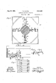
Aug. 20, 1935. R, WATTS ELECTRICAL MEASURING APPARATUS Filed May 3, 1953 I 2 Sheets-Sheet l INVENTOR 7770mas R Waits. mml xxr Aug.20, 1935. R WATT 2,011,665
ELECTRICAL MEASURING APPARATUS Filed May 3, 1933 2 Sheets-Sheet 2 INVENTOR Thomas R Walls.
SAES
ELECTRICAL MEASURING APPARATUS Thomas R. Watts, Forest Hills, Pa., assignor to Westinghouse Electric & Manufacturing Company, East Pittsburgh, Pa., a corporation of Pennsylvania Application May 3, 1933, Serial No. 669,170 16 Claims. (Cl. 175-183) My invention relates, generally, to electrical measuring apparatus and it relates particularly to apparatus for obtaining magnetic measurements.
The objectof my invention, generally stated. is the provision of magnetic testing apparatus for detectingfiaws in magnetic material which shall be simple, efficient and accurate in operation and which may be readily and economically manufactured, installed and operated.
The principal object of my invention is to provide for detecting the non-homogeneous character of magnetic material. 7
Another object of my invention isto provide for detecting the non-homogeneous character of magnetic material while the material its1lf is being moved relative to the detecting apparatus.
A further object of my invention is to provide for signalling to an operator the presence or existence of a slight flaw in magnetic material being tested.
Still another object of my invention is to provide additional signalling means for indicating to an operator the presence or 'existence of a relatively large flaw in magnetic material being tested.
Another object of my invention is to provide for testing bars of magnetic material of varying size with the same testing apparatus.
Other objects of my invention will in part be obvious and in part appear hereinafter.
My invention, accordingly, is disclosed in the embodiment hereof shown in the accompanying drawings and comprises the features of construction, combination of elements and arrangement of parts which will be exemplified in the construction hereinafter set forth and the scope of ticular embodiment of my invention,
Fig. 2 is an enlarged view, illustrating in more" detail the mounting of the measuring instruments used in practicing my invention,
Fig. 3 is an enlarged sectional view taken along the line IIIIII of Fig-1,
Fig. 4 is an enlarged view of one of the measuring instruments, certain parts being broken away to more clearly illustrate the construction,
Fig. 5 is an enlarged sectional view taken along the line VV of Fig. 4,
Fig. 6 is an enlarged sectional view taken along the line VI-VI of Fig. 4, and
Fig. '7 is a diagrammatic representation of the signalling circuits which may be used in conjunction with the measuring instruments.
Referring now particularly to Fig. 1 of the drawings, the reference character l designates a bar of magnetic material such as rolled steel, the character of which it is desired to test in order to ascertain whether there are any serious flaws incorporated therein. It is particularly desirable to ascertain the character of bars of this type which may be used in the construction of such parts as axles for use in the construc-. tion of automobiles, railroad cars or the like without subjecting them to destructive tests or applying such tests as. involve the use of expensive apparatus such as X-ray equipment. It willbe readily understood that it is desirable to provide a simple and economical testing appara-' tus which will indicate the character of steel bars or the like with a considerable degree of rapidity, so that the cost of testing material of this'type may be reduced to a minimum.
In order to obtain an indication of the homogeneity of the bar l0, an armature II is provided which,.as illustrated, is of substantially U-shape. The ends of the armature II are provided with transverse aligned openings l2 and I3 through which the bar it may be driven by means of rollers I8 one or more of which may be driven by means of a motor I5. The motor I may be of any suitable type, such as a shunt wound direct current motor, as illustrated, and may be provided with a rheostat 16 for varying the speed thereof, as will be readily understood. As shown, the rollers M are disposed to cooperate in such manner as to guide the bar l0 through the openings l2 and H5 in the armature H.
In order to provide for the testing of bars of different diameters, the openings l2 and I3 are formed large enough to accommodate the largest diameter of a bar which it is desired to test. When it is desired to test a bar of smaller diameter, removable collars l6 and ll, of magnetic material, may be positioned in the openings l2 and I3, in order to reduce the air gap, between the armature II and the bar Hi, to a minimum. It will be readily understood that the collars l6 and I! may be of difl'erent thicknesses in order to accommodate bars of different diameters;
It is desirable to accurately center the bar I0 within the openings l2 and I3 in order to maintain a uniform air gap around the bar I9 in-the openings l2 and 13. For this purpose rollers l9 are provided in suitable frames 20 which may be slidably mounted upon the armature II, as illustrated, and adjusted by means of an adjusting screw 2| to center the bar 10, as desired.
With a view to generating magnetic flux, both within and along the bar 10, a magnetizing winding 22 is provided around the central portion of the armature II, as illustrated. This windin may be supplied with direct current from any' suitable source. An ammeter 23 is provided for measuring the amount of current that is supplied to the magnetizing winding 22 and a rheostat 24 is also provided for varying the amount of current supplied, as may be desired.
In the event that the bar l0 being tested is generally of homogeneous structure and no flaws such as cracks, pipes or the like are present therein,
the distribution of the magnetic flux within the bar 10 and the leakage flux along it will be substantially uniform. However, if a flaw or crack is present in thebar in, its presence will alter the character of themagnetic field in the vicinity of the flaw or crack and will tend to increase the density of the leakage flux in this vicinity. There fore, if a sensitive flux measuring device is provided for giving an indication of the density of the leakage flux, as the bar 10 is moved through the armature I I, it will be possible to detect flaws which may be present.
While a simple instrument that will indicatevariations in flux density may be used; theoretically, for determining the character of the bar 16 as it is-moved, it has been found in practice that such apparatus is not entirely satisfactory because of the fact that the conditions external to the'bar 10 may not be entirely uniform under all circumstances and that, under certain conditions, a simple magnetic measuring instrument might indicate the presence of a flaw when, in fact, no
flaw existed. These variations may be due to variations in the density of the leakage 'fiulxnear the ends of the bar ill being tested as it enters or leaves the testing apparatus, to variations in the air gap between the armature and the bar ill, or due to other'cause's, and, as a result, variations in the density of the leakage flux may occur, al-
' though the bar-l 0 may be entirely free from flaws.
Under certain conditions, these variations would indicate that a fiaw was present and for this reason the bar being tested might be rejected because of this apparent indication although, in
fact, the indication that a flaw was presentwas due to variations in the density "of the leakage flux which were caused'by conditions external to the bar 10;
Therefore, in view of the foregoing, it is highly desirable to provide a magnetic measuring instrument which will be sensitive only to variations in the homogeneous character of the bar 16 and which .will not be responsive to variations which are caused by conditions external to the bar 10 itself. An instrument of this type is illusstrated generally at 25 in Figs. 2 and 3 of the drawings and it may be mounted, as illustrated,
- on an articulated frame shown generally at 26.
The articulated frame 26 comprises a support member 21 to which the instrument 25 may be secured by any suitable means and which is provided with downwardly extending arms 28 on which rollers 29 are mounted. The rollers 29 are arranged to engage the bar 10 being tested and to maintain the lower edge of the instrument 25 in close proximity to the bar IO' and only their non-residual characteristics. v
slightly spaced therefrom. The supporifmernber 21 may be carried by means of arms 41 which are hinged to the top of the support member 21 at the lower ends and are also hinged to the under side of a cross member 30. A tension spring 3| is provided :for exerting a-bia s'ing force on the articulated frame 26 to maintain the rollers 29 in engagement with the bar Ill;
The cross members 30 of the articulated frames 26 may be secured to a main"frame,:.illu"strated generally at 32. mounted by any suitable means, notshown, be-
' tween the ends of the armature H in such posibias the frame 25 inwardly in a radial direction.
It is desirable tov limit this movement to a certain extent in order to facilitate the positioning of the bar 10 within the testing apparatus. 7 For this reason, one of the arms 41 is provided with an extension member 33 with which an adjusting screw 34 is arranged to cooperate to limit'the inward radial movement of the frame 26 to any desired position. 1
Referring now particularly to Figs. 4, 5 and 6 of the drawings, it will be observed that the instru-' ment 25 is shown in greater detail. In this instance, the instrument 25 illustrated as being comprised of two instruments 35 and 36 which may be of the repulsion vane type or any other suitable type.
The instrument 35 comprises a stationary vane 31, which is mounted on a suitable non-magnetic support member 38, and a movable vane 39 which is rotatably mounted .on a support member 40,
which may also be of non-magnetic material, by means of bearing members 41 and a shaft 42, as illustrated. The vanes 31 and 39 are preferably formed of non-residual magnetic steel. It will be understood that when vanes of this character are used, they will repel each other when subjected to a. magnetic field for the reason that they are similarly magnetized. However, as soon as themagnetic field is removed, the vanes 31 and 39 will return to their normal position, because of The main frame 32 maybe At one end of the shaft 42 an arm or pointer 43 I isprovided which is adapted to carry' a single contact member 44. A coil spring 44a is provided, as illustrated, for biasing the shaft 42 and thereby the vane 39 to the non-magnetized position.
The instrument 36 is identical with the instrument 35 with the exception that it is arranged to deflect in the reverse direction. That is, in the instrument 36 the relative position of the vanes 31 and 39 is reversed so that the application of a' magnetic field to both instruments causes the arms 43 to move in the same direction. However, the arm 43 of the instrument 3B is provided with a bifurcated contact member 45, the arms of which are disposed in the path of the contact member 44, as illustrated in Fig. 6.
In addition, a stationary contact member 46 65. They. however,
. the contact member may be mounted on the instrument 35 for a purpose which will be set forth hereinafter.
While it is possible to obtain an indication of the character of the bar H] by observing the relative position of the contact member 54 between the arms of the contact member 45, it is preferable to provide a suitable signalling means so that an operator using the testing apparatus need only observe the signalling apparatus rather than the relative position of the contact members M and 45. i
As is more clea ly illustrated in Fig.7 of the drawings, indicating lamps 48 and 49 may be provided individual to each of the sets of contact members M and 45, as illustrated. The indicating lamps 48 and 69 may be individually connected to conductors5ii and 5! which may be energized from any suitable source of current.
It will be apparent that the indicating lamps 48 and 69 may be arranged on any suitable mounting,
such as a panel or the like, where they will be convenient to the view of the operator. Since the position of the indicating lights 58 and 49 may generally be determined by the physical conditions under which the testing of the bars I is performed, their relative mechanical position with respect to the testing apparatus is not shown.
In operation, suitable magnetizing current is supplied to the magnetizing winding 22, as desired, and-the motor I is energized to move the be! H) throughthe openings 12 and [3 in the armature H. The energization of the winding 22 generates a magnetic flux in the bar l0 and a leakage flux along it, as described hereinbefore. Since the vanes 31 and 39 of the instruments 35 and 35 are positioned in the field of the leakage flux, it will be readily apparent that they will be repelled from each other and that the arms 43 operated by the movable vanes as will be moved to a position depending upon the density of the leakage ilux to which they are subjected. However, if the density of the flux of the leakage field, as applied to both instruments 35 and 36 is the same, there will be substantially no relative movement between the contact members it and will move to some position which may be termed the normal position to which they will be actuated when the character of the bar is entirely uniform and free from flaws or defects.
In the event that'a slight flaw is present under one of the instruments 35, for example, the leakage fiux which will be applied to thevanes 31 and 39 of this instrument will be greater than that which is applied to the corresponding vanes oi the instrument 35. If this difference in flux density is sufficiently great, the contact member at will be moved relative to one of the arms of 55 so that it will engage it, thereby connecting the indicating lamps 48 and 59 in series circuit relation to the-energized conductors 50 and iii. If the flaw is relatively small, the continued movement of the bar I!) will cause it to pass from underneath the instrument and to increase the density or the leakage flux that is applied to the vanes of the instrument 36. The contact member 65 will then be moved relative to the contact member 54 and the indicating lights 58 and 69 will again be energized. An operator observing the two successive illuminations of the indicating lamps G8 and 49 will then be immediately aware that a slight flaw is present in the bar it and he may to further investigate. that the operator will then stop the motor Hi It will also be observed be generally informed as the bar Iii and by observing to the particular part of the circumference of the bar III at which the flaw is present by observing which set of the indicating lights 48 and 49 has been energized.
In the event that a relatively large flaw or void is present in the bar 10, a relatively great the density of the leakage change will occur in flux surrounding it and this change will be reflected in a marked deflection of the instruments 35 and 36. If it is assumed that the large flaw .or void is first moved into proximity with the instrument 35 and a flux of relatively large density is applied to the vanes 3'! and 39 of this instrument, the contact member 64 will be moved into engagement with the contact member 45. However, due to the extremely high density to which the instrument 35 is subjected, sufficient torque will be applied to move the contact member into engagement with the fixed contact member 46. It will then be observed that each of the indicatinglamps 48 and 49 nected directly. across the energized conductors and 5|, and as a result. they will be brilliantly illuminated. The operator will then be informed that a relatively large flaw or void is present in the particular set of lamps that are brilliantly illuminated, he may determine the particular part of the bar ill in which the flaw is present.
In the event that a relatively long pipe of gradually increasing size is present in the bar l0 being tested, it will be apparent that there will be slight, if any, diiference in the density of the leakage flux as applied to the instruments 35 and 36. For this reason, the contact member A l may not move relative to the contact member 45 sufficiently far to indicate to the operator that a flaw is present. However, if the pipe is sufflciently large to materially alter the density of the leakage flux, the contact member 45 will engage the stationary contact member 46. The operator, noting that the lamps 48 and 49 have been illuminated to the maximum brilliancy, will then be aware of the type of flaw which may be present under the instruments 35 and 36.
In order to obtain satisfactory operation of the testing apparatus described hereinbeiore, it is desirable to adjust the amount of flux generated by the magnetizing winding 22', so that the best operating conditions may be obtained. It is also desirable to provide a suitable tension in the springs 44a, that are used to bias the movable vanes 39 to the normal positions, so that the apparatus will not be too sensitive. However,
' after the necessary preliminary adjustments have been made, a succession of the bars Hi may be moved through the armature H. The testing of the bars may thus assume the form of a continuous operation by means of which imperfect matewill be conshown in the accompanying drawings shall be interpreted as illustrative and not in a limiting sense.
I claim as my invention:
1. In apparatus for testing the condition of magnetic material, in combination, means for magnetizing the material to be. tested, means responsive to variations in leakage flux disposed at spaced positions along said material, and diflerential means mechanically operated by said flux responsive means for indicating a difference in the leakage flux density between said spaced positions.
2. In apparatus for detecting flaws or the like in magnetic material, in combination, means for magnetizing the material to be tested, means re-.
I cordance with the operation of said magnetic means for indicating a difference in the leakage flux density between said spaced positions, and additional means for indicating the leakage flux density at one of said points when it exceeds a predetermined value.
4. In apparatus for detecting flaws or the like in magnetic material, in combination, magnetizing means disposed'to produce leakage flux along the material to be tested, a plurality of individually responsive flux density measuring means disposed at spaced positions along said material,
and diiferential indicating means mechanically operated by said measuring means in accordance with the difference in the flux densities between said positions to reveal the presence of a nonhomogeneous portion of said material at one of said positions.
5. In apparatus for detecting flaws or the like in magnetic material, in combination, circuit means forapplying a magnetomotive force to said material to produce leakage flux therealong, a plurality of independently operable flux density measuring means disposed at spaced positions along said material, indicating means controlled by said measuring means in accordance with the difference in the flux densities betweensaid positions to reveal the presence of a non-homogeneous portion of said material at one of and additional indicating means said positions, controlled; by
said measuring means and operative on the aplication of leakage flux of relatively high density, at one of said positions to reveal the presence of a relatively large non-homogeneous portion of said material.
6.-Apparatus for detecting non-homogeneous portions or magnetic material in the form of bars or the like comprising, in combination, anarmature of substantially U shape having transverse aligned openings in the ends thereof through which a bar to be tested may be passed, a winding connected to a source of electrical energy forenergizing the armature to generate magnetic flux within and along the bar as it is moved, and a plurality of flux measuring devices disposed .around said bar and within the armature for obtaining indication of the density of the leakage flux along the bar, thereby indicating the relative homogeneity of the bar as it is moved through the armature,
7. Apparatus for detecting non-homogeneous portions of magnetic material in-the form of" bars or the like comprising, in combination. an
, engagement. on the mined difierence in armature of substantially U shape having transverse aligned openings in the ends thereof through which abar to be tested may be passed, a winding connected to a source of electrical energy for energizing. the armature to generate magnetic flux within and along the bar as it is moved, a plurality oi flux measuring devices disposed around said bar and within the"armature, and signalling means individual to each of said flux measuring devices and adapted to be energized thereby when the leakage flux exceeds a predetermined density thereby indicating the relative homogeneity of the bar as it is moved through saidfield. K
8. Apparatus for detecting non-homogeneous portions of magnetic material in the form of bars or the like comprising, in combination, an
armature of substantially U shape having transverse aligned opening in the ends thereof through which a bar to be tested may be passed, a; windaround said bar andwithin the armature, each of said flux measuring devices comprising a. pair of instruments of the repulsion vane type dis- "posed in tandem longitudinally along the bar, a
fixed and a movable vane-in each of said instruments, contact members carried by the movable vanes and disposed to come into contact engagement on the occurrence of a predetermined difference in the flux densities measuredby each instrument regardless of which instrmnent is subjected to the greater flux, and signalling means connected to a current source and to said contact members for indicating when said contact membars are closed. v 9. Magnetic flux density measuring means comprising, in combination, .a pair of instruments of the repulsion vane type adapted to be mounted in spaced relation in the magnetic field to be measured, and indicating means operated in accordance with the movement of the vanes in the instruments and disposed differentially to permit a comparison of the flux densities measuredby each instrument.
10. Magnetic flux density measuring means comprising, in combfnation, a pair of instruments of the repulsion vane type adapted to be mounted in spaced relation in the magnetic field to be measured, afixed and a movable vane in each instrument, contact members carried by the movable vanes engagement on the occurrence of a predetermined difference in the flux densities meamired anddisposed to come into contact 11. Magnetic fluxdensity measuring means comprising, in combination, a pair of instruments of the repulsion vane type adapted to be mounted in spaced relation in the magnetic field to be measuredfa' fixed and a movable vane in each instrument, contact members carried by the movable vanes and disposed to come into contact the flux densities measured occurrence of a predeterby each instrument, a stationary contact member mounted in the path of the movable contact members and disposed to be engaged thereby on the occurrence of a, relatively high flux density m asured by said instruments, signalling means connected to a current source and to said movable contact members for indicating the existence of said predetermined difference in the flux density as measured by each instrument, and circuit means connecting the current source to the stationary contact member to effect a different operation of the signalling means to indicate the existence of said relatively high flux density.
12. Magnetic flux density measuring means.
comprising, in combination, a pair of instruments of the repulsion vane type adapted to be mounted in spaced relation in the magnetic field to be measured, a fixed and a movable vane in each instrument, interfitting contact members carried by the movable vanes and disposed to come into contact engagement on the occurrence of a predetermined difierence in the flux densities measured by each instrument regardless of which in strument is subjected to the greater flux density, and signalling means connected to a current source and to said contact members for indicating when said contact members are closed;
13. Magnetic flux density measuring means comprising, in combination, a pair of instruments of the repulsion vane type adapted to be mounted in spaced relation in the magnetic field to be measured, a fixed and a movable vane in each instrument, interfitting contact members carried by the movable vanes and disposed to come into contact engagement on the occurrence of a predetermined difference in the fiux densities measured by each instrument regardless of which instrument is subjected to the greater flux density,
a stationary contact member mounted in the path' of the movable contact members and disposed to be engaged thereby on the occurrence of a relatively high flux density measured by said instruments, signalling means connected to a current source and to said movable contact members for indicating the existence of said predetermined difference in the fiuxdensity as measured by each instrument, and circuit means connecting the current source to the stationary contact member to effect a different operation of the signalling means to indicate the existence of said relatively high flux density.
14. In apparatus for detecting non-homogeneous portions of magnetic material in the form of bars or the like, in combination, electro-magnetic means for generating a magnetic field within and along a bar to be tested, a main frame disposed in the magnetic field around the bar, a plurality of flux measuring devices spaced around the bar to obtain indications of whesdensity ggwfi the leakage flux along the bar, an articulated frame for supporting each flux measuring device a mounted on the main frame, resilient means operatively connected to each articulated frame for biasing the flux measuring devices radially in- 'wardly to maintain them in substantially constant spaced relation relative to bars of varying size, and adjustable stop means mounted on each articulated frame for preventing the inward movement of the flux measuring device individual thereto beyond a predetermined range of of the magnetic circuit at said openings to a I minimum for each size, a winding connected to a source of electrical energy for energizing the armature to generate magnetic flux within and along the bar as it is moved, and a plurality of flux measuring devices disposed around said bar and within the armature for obtaining indications of the density of the leakage flux alongthe bar thereby indicating the relative homogeneity of the bar as it is moved through the armature.
16. Apparatus for testing the condition of a specimen of magnetic material comprising, in combination, means for magnetizing the specimen to be tested, and a plurality of flux density measuring means disposed at different positions adjacent to said specimen within the field generated by said magnetizing means, each of said measuring means comprising a pair of differentially related spaced flux measuring pointers disposed to indicate any difference in the flux densities at said devices. THOMAS R. WATTS.
Priority Applications (1)
| Application Number | Priority Date | Filing Date | Title |
|---|---|---|---|
| US669170A US2011665A (en) | 1933-05-03 | 1933-05-03 | Electrical measuring apparatus |
Applications Claiming Priority (1)
| Application Number | Priority Date | Filing Date | Title |
|---|---|---|---|
| US669170A US2011665A (en) | 1933-05-03 | 1933-05-03 | Electrical measuring apparatus |
Publications (1)
| Publication Number | Publication Date |
|---|---|
| US2011665A true US2011665A (en) | 1935-08-20 |
Family
ID=24685351
Family Applications (1)
| Application Number | Title | Priority Date | Filing Date |
|---|---|---|---|
| US669170A Expired - Lifetime US2011665A (en) | 1933-05-03 | 1933-05-03 | Electrical measuring apparatus |
Country Status (1)
| Country | Link |
|---|---|
| US (1) | US2011665A (en) |
Cited By (4)
| Publication number | Priority date | Publication date | Assignee | Title |
|---|---|---|---|---|
| US2770773A (en) * | 1954-12-27 | 1956-11-13 | Stanolind Oil & Gas Co | Detecting corrosion of well casing |
| US2892150A (en) * | 1953-05-12 | 1959-06-23 | Nettles Forrest Truett | Thickness gauge |
| US3015063A (en) * | 1960-06-23 | 1961-12-26 | Camco Inc | Magnetic caliper |
| US3247453A (en) * | 1961-03-09 | 1966-04-19 | Api Instr Company | Magnetic flaw detector with exciting and sensing coils axially aligned on opposite sides of the material |
-
1933
- 1933-05-03 US US669170A patent/US2011665A/en not_active Expired - Lifetime
Cited By (4)
| Publication number | Priority date | Publication date | Assignee | Title |
|---|---|---|---|---|
| US2892150A (en) * | 1953-05-12 | 1959-06-23 | Nettles Forrest Truett | Thickness gauge |
| US2770773A (en) * | 1954-12-27 | 1956-11-13 | Stanolind Oil & Gas Co | Detecting corrosion of well casing |
| US3015063A (en) * | 1960-06-23 | 1961-12-26 | Camco Inc | Magnetic caliper |
| US3247453A (en) * | 1961-03-09 | 1966-04-19 | Api Instr Company | Magnetic flaw detector with exciting and sensing coils axially aligned on opposite sides of the material |
Similar Documents
| Publication | Publication Date | Title |
|---|---|---|
| US1998952A (en) | Rail inspection apparatus | |
| US4218651A (en) | Apparatus for detecting longitudinal and transverse imperfections in elongated ferrous workpieces | |
| US2065118A (en) | Method and apparatus for testing metals for defects | |
| US1992100A (en) | Testing flaws and the like in working materials | |
| US2124577A (en) | Method and apparatus for testing metal articles for defects | |
| US6377040B1 (en) | Eddy current probe and process for checking the edges of metal articles | |
| US2432948A (en) | Electric coil testing device | |
| US2701336A (en) | Flaw detector | |
| US2011665A (en) | Electrical measuring apparatus | |
| US1954975A (en) | Method and apparatus for testing electrically conducting bodies | |
| US2540589A (en) | Magnetic testing recording system for metallic bodies | |
| US1944954A (en) | Flaw detector for electrical conductors | |
| US3437918A (en) | Inductive bridge circuit for flaw sensing in which all coils of the bridge are positioned adjacent the test piece | |
| US2031469A (en) | Method and means for detecting flaws | |
| US2485285A (en) | Strip elongation indicator | |
| US1859020A (en) | Method of and apparatus for measuring materials | |
| USRE15859E (en) | burrows | |
| US2758276A (en) | Apparatus for the non-destructive testing of magnetizable objects | |
| US2102452A (en) | Detection of flaws in magnetizable bodies | |
| JPS60237358A (en) | Ultrasonic inspection method and device for conductive material to be inspected | |
| US2054020A (en) | Magnetic sheet tester | |
| US2055672A (en) | Metal testing device | |
| US3293543A (en) | Magnetic ink tester utilizing a. c. or d. c. magnetization and visual indications | |
| US2416090A (en) | Strain measuring and recording apparatus | |
| US2124578A (en) | Apparatus and method for testing metal articles |