US20100228170A1 - Lower back supporter - Google Patents
Lower back supporter Download PDFInfo
- Publication number
- US20100228170A1 US20100228170A1 US12/381,202 US38120209A US2010228170A1 US 20100228170 A1 US20100228170 A1 US 20100228170A1 US 38120209 A US38120209 A US 38120209A US 2010228170 A1 US2010228170 A1 US 2010228170A1
- Authority
- US
- United States
- Prior art keywords
- anchor
- lower back
- belts
- support
- pair
- Prior art date
- Legal status (The legal status is an assumption and is not a legal conclusion. Google has not performed a legal analysis and makes no representation as to the accuracy of the status listed.)
- Granted
Links
- 239000000463 material Substances 0.000 claims abstract description 17
- 210000001015 abdomen Anatomy 0.000 claims abstract description 13
- 230000003187 abdominal effect Effects 0.000 description 5
- 238000000034 method Methods 0.000 description 5
- 230000006870 function Effects 0.000 description 4
- 208000008930 Low Back Pain Diseases 0.000 description 3
- 239000000853 adhesive Substances 0.000 description 3
- 210000004705 lumbosacral region Anatomy 0.000 description 3
- 208000010201 Exanthema Diseases 0.000 description 2
- 230000006378 damage Effects 0.000 description 2
- 201000005884 exanthem Diseases 0.000 description 2
- 239000006260 foam Substances 0.000 description 2
- 206010037844 rash Diseases 0.000 description 2
- 229920002379 silicone rubber Polymers 0.000 description 2
- 208000025978 Athletic injury Diseases 0.000 description 1
- 229920000742 Cotton Polymers 0.000 description 1
- 208000036366 Sensation of pressure Diseases 0.000 description 1
- 208000027418 Wounds and injury Diseases 0.000 description 1
- 239000004744 fabric Substances 0.000 description 1
- 239000000835 fiber Substances 0.000 description 1
- 208000014674 injury Diseases 0.000 description 1
- 238000011084 recovery Methods 0.000 description 1
- 239000011347 resin Substances 0.000 description 1
- 229920005989 resin Polymers 0.000 description 1
- 230000000284 resting effect Effects 0.000 description 1
- 230000000087 stabilizing effect Effects 0.000 description 1
- 239000000126 substance Substances 0.000 description 1
- 229920002803 thermoplastic polyurethane Polymers 0.000 description 1
Images





Classifications
-
- A—HUMAN NECESSITIES
- A61—MEDICAL OR VETERINARY SCIENCE; HYGIENE
- A61F—FILTERS IMPLANTABLE INTO BLOOD VESSELS; PROSTHESES; DEVICES PROVIDING PATENCY TO, OR PREVENTING COLLAPSING OF, TUBULAR STRUCTURES OF THE BODY, e.g. STENTS; ORTHOPAEDIC, NURSING OR CONTRACEPTIVE DEVICES; FOMENTATION; TREATMENT OR PROTECTION OF EYES OR EARS; BANDAGES, DRESSINGS OR ABSORBENT PADS; FIRST-AID KITS
- A61F5/00—Orthopaedic methods or devices for non-surgical treatment of bones or joints; Nursing devices ; Anti-rape devices
- A61F5/01—Orthopaedic devices, e.g. long-term immobilising or pressure directing devices for treating broken or deformed bones such as splints, casts or braces
- A61F5/02—Orthopaedic corsets
- A61F5/028—Braces for providing support to the lower back, e.g. lumbo sacral supports
Definitions
- the present invention relates to a new lower back supporter alternative to a known lower back taping which is used for reducing and preventing recurrence of lower back pain.
- the tape used in taping has problems. It is difficult to handle when it is being applied because of its adhesiveness, and a rash would occur on the skin of a wearer due to the adhesive agent depending on the physical constitution of the patient.
- tape removed from the body cannot be reused and has to be disposed of, and thus new tape is required with each application, and further it is necessary to have the tape applied by an expert.
- lower back supporters generally do not have the problems mentioned above and can be easily put on.
- these supporters are of a type that may increase abdominal pressure to stabilize the lower back, there is a strong sensation of pressure on the abdomen, and the problem is that such supporters are uncomfortable and painful to wear for a long time, and they can slip easily while being worn (they can slip easily especially upward).
- the present invention is created taking into consideration of the problems described above with the conventionally lower back taping and lower back supporter, and it is an object of the present invention to provide a new lower back supporter which, while having the same function as conventional taping, does not have the above-described problems specific to taping and is as easy to wear as in a conventional lower back supporter, but is not uncomfortable to wear for a long time, and further is prevented from slipping while it is being worn.
- the lower back supporter of the present invention comprises: a pair of flat first and second anchor parts of which inner side surfaces comprising a non-slip material which closely contacts a skin of a wearer and of which outer side surfaces comprising a material to which a surface fastener is fastened, the pair of anchor parts coming into contact with a lower back of the wearer with a specified space in between; a pair of anchor belts connected respectively to the pair of anchor parts and brought to an abdomen side of the wearer so that end portions of the anchor belts are coupled to each other; a first support belt connected to the first anchor part and brought to the second anchor part through a central back side so that the first support belt is fastened to the outer side surface of the second anchor part via a surface fastener; and a second support belt connected to the second anchor part and brought to the first anchor part through the central back side of the wearer so that the second support belt is fastened to the outer side surface of the first anchor part.
- the pair of anchor parts When this supporter is worn, the pair of anchor parts are brought to come into contact almost laterally in a symmetric manner with suitable positions ranging from the sides of the waist to the central back area of a wearer, though the pair of anchor belts can be omitted.
- the above-described lower back supporter can be further comprised of a center connecting belt that connects the pair of anchor parts and provided on the inner side surface sides of the first and second support belts; and it can, with or without the center connecting belt, be equipped with a pair of operation belts respectively connected to the end portions of the first and second support belts.
- the anchor parts when the anchor parts are put on the lower back, the inner side surfaces of the anchor parts closely contacts the skin of a wearer and does not slide, and the anchor parts play a role of anchor tape of conventional taping; and in addition, the first and second support belts that are connected to and fastened to that anchor parts have a role of a support tape of conventional taping.
- the anchor belts play a role of securing a close contact of the anchor parts' inner side surface with the skin of the wearer and of eliminating the slippage.
- the anchor belts can be omitted.
- the lower back supporter of the present invention functions the same way as conventional taping and provides pressure, support, restriction and immobilization of the lower back, and it disperses the impact applied to the lower back and reduces and prevents recurrence of lower back pain; and it can be used instead of conventional taping.
- the lower back supporter of the present invention is not directly put on the skin of a wearer using adhesive agent; accordingly, no concern of rash occurring on the skin of a wearer is required. Also, the same lower back supporter can be used any number of times, and it is less expensive than conventional taping. Furthermore, though it is necessary in conventional taping to rely on an expert when it is put on, the lower back supporter of the present invention can be easily worn by the patient just like conventional supporters; and after having it put on, if there is a sense of discomfort such as restriction, pressure or the like, it can be easily removed and then put back on, which is advantageous.
- FIG. 1 shows the outer side of the lower back supporter of the present invention
- FIG. 2 shows the inner side of the lower back supporter
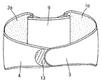
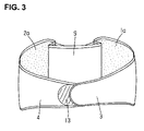
- FIG. 3 shows the lower back supporter, seen from the back side, in the process of being put on
- FIG. 4 shows the lower back supporter, seen from the abdominal side, in the process of being put on
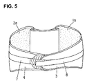
- FIG. 5 shows the lower back supporter, seen from the back side, in the state that it is worn
- FIG. 6 shows the lower back supporter, seen from the abdominal side, in the state that it is worn
- FIG. 7 shows the outer side of another lower back supporter of the present invention.
- FIG. 8 shows the inner side thereof
- FIG. 9 shows the outer side of yet another lower back supporter of the present invention.
- FIG. 10 shows the inner side thereof.
- the lower back supporter shown in FIGS. 1 and 2 is comprised of a pair of anchor parts 1 and 2 arranged with a specified space in between and anchor belts 3 and 4 connected respectively to the anchor parts 1 and 2 ; and it is further comprised of a first support belt 5 , which is connected to the anchor part 1 and brought to the anchor part 2 via the central back side of the lower back and fastened to the outer side surface of the anchor part 2 , and a second support belt 6 , which is connected to the anchor part 2 and brought to the anchor part 1 via the central back side of the lower back and fastened to the outer side surface of the anchor part 1 .
- Operation belts 7 and 8 are respectively connected to the first and second support belts 5 and 6
- a connecting belt 9 is provided between the anchor parts 1 and 2 so as to connect the anchor parts 1 and 2 .
- the inner side surfaces (areas 1 a and 2 a shown by the dots in FIG. 2 ) of the anchor parts 1 and 2 are comprised of a material that can closely contact the skin of a wearer and does not slip easily.
- Preferable materials include, among others, a foam resin (foam urethane resin or the like) and silicon rubber.
- the outer side surfaces (areas 1 b and 2 b shown by the diagonal lines in FIG. 1 ) of the anchor parts 1 and 2 consist almost entirely of a material to which a surface fastener can be fastened such as pile fabric or the like.
- Stays 11 which are hard and narrow in width, are attached to the inside edges (edge portions toward the center) of the anchor parts 1 and 2 .
- the anchor parts 1 and 2 as a whole consist of a flexible material.
- the anchor parts 1 and 2 as a whole have a stretchability derived from the elasticity.
- the anchor parts 1 and 2 nonetheless, do not need to have the ability to stretch.
- the pair of anchor parts 1 and 2 are provided so that they have a space between them and have their horizontal width so that the anchor parts 1 and 2 are, when the lower back supporter is put on a wearer, in contact with a suitable lateral position extending from both sides of the waist toward the back of the wearer, preferably from the center point of each side of the body to the back side in the waist area of the wearer.
- a suitable length is selected so that the anchor parts 1 and 2 provide sufficient coverage vertically for the site of soreness as the center; and for the horizontal width, such width is selected so that the coverage necessary to ensure a close contact of the inner side surface of the anchor parts 1 and 2 with the skin of the wearer is assured (so that the supporter is prevented from slipping when tensile force is applied to the supporter from the first and second support belts 5 and 6 or when the wearer bends his body, for example).
- the anchor belt 3 is sewn at its base part onto the outside edge (referred to by 1 c ) of the anchor part 1 , and a surface fastener 12 (shown by the check marks in FIG. 2 ) is attached to the inner side surface of its end portion.
- the anchor belt 4 is sewn at its base part onto the outside edge (referred to by 2 c ) of the anchor part 2 , and a receiving piece 13 (shown by the diagonal lines in FIG. 1 ) to which the surface fastener 12 of the anchor belt 3 is fastened is attached to the outer side surface of its end portion.
- the anchor belts 3 and 4 consist entirely of a flexible material and have stretchiness (elasticity).
- the anchor belts 3 and 4 preferably have stretchiness that can release the pressure on the abdomen when the lower back supporter is put on. Nonetheless, it is not essential for the anchor belts 3 and 4 to have stretchiness.
- the first and second support belts 5 and 6 consisting of a flexible material are respectively formed substantially in a V shape.
- the base parts (open side of the V shape) of the first support belt 5 is sewn onto the inside edge (inside of the stay 11 ) of the anchor part 1 , and a surface fastener 14 which fastens to the outer side surface 2 b of the anchor part 2 is attached to the inner side surface of the pointed end portion (bottom of the V shape).
- the base parts (open side of the V shape) of the second support belt 6 is sewn onto the inside edge (inside of stay 11 ) of the anchor part 2 , and a surface fastener 15 which fastens to the outer side surface 1 b of the anchor part 1 is attached to the inner side surface of the pointed end portion (bottom of the V shape).
- the tensile force from the first and second support belts 5 and 6 is distributed almost evenly over the entire anchor parts 1 and 2 as a whole.
- the reason for making the support belts 5 and 6 substantially V-shape is to allow these belts to cross over in opposite directions to avoid interference with each other and to apply tensile force as evenly as possible to the anchor parts 1 and 2 . Nonetheless, it is not essential that the support belts 5 and 6 be in substantially a V-shape.
- the operation belt 7 is connected at its base part to the pointed end portion of the first support belt 5 , and a receiving piece 16 fastened to a surface fastener is attached to the outer side surface of the end portion of the operation belt 7 .
- the operation belt 8 is connected at its base part to the pointed end portion of the second support belt 6 , and a surface fastener 17 fastened to the receiving piece 16 of the operation belt 7 is attached to the inner side surface of the end portion of the operation belt 8 .
- the V-shaped first and second support belts 5 and 6 have stretchiness of relatively strong elasticity. If the focus is on resting of the lower back when wearing the lower back supporter, then the first and second support belts 5 and 6 can be formed without the stretchiness; however, if movement of the lower back is desired, then elastic belts can be employed for them. Either type may be selected according to the purpose; however, it is generally preferable that the first and second support belts 5 and 6 have a certain amount of stretchiness to meet both demands.
- the operation belts 7 and 8 are held by hands when putting the lower back supporter on; and they are used to pull the first and second support belts 5 and 6 laterally, and they do not have elasticity (stretchiness). More specifically, these operation belts 7 and 8 are provided to improve the operability in pulling the first and second support belts 5 and 6 laterally, and the presence or absence of stretchiness is not essential. However, it is somewhat preferable that the operation belts 7 and 8 do not have stretchiness so that pulling force is transmitted directly to the first and second support belts 5 and 6 as noted above. In the present invention, the operation belts 7 and 8 are not essential elements.
- the connecting belt 9 is provided to prevent the anchor parts 1 and 2 from being separated, and they improve the operability of the lower back supporter when it is put on or stored.
- the connecting belt 9 is comprised of a flexible material and has stretchiness (elasticity).
- stretchiness elasticity
- the connecting belt 9 can be the same as that of the anchor belts 3 and 4 .
- the connecting belt 9 is, nonetheless, not an essential element.
- the procedure for putting on the lower back supporter shown in FIGS. 1 and 2 will be described.
- the anchor parts 1 and 2 are fitted almost symmetrically on the left and right sides of the lumbar spine, and the inner side surfaces 1 a and 2 a of the anchor parts 1 and 2 are brought into a close contact with the skin of both sides of the lumbar spine; then while lightly applying pulling force, the anchor belts 3 and 4 are wrapped around the abdomen side, and the surface fastener 12 of the anchor belt 3 is fastened to the receiving piece 13 of the anchor belt 4 so that the supporter is secured around the waist.
- the anchor parts 1 and 2 are at positions ranging from the center point of each side of the body to the back side in the waist area.
- the operation belts 7 and 8 are pulled left and right to apply tensile force to the support belts 5 and 6 ; and then the surface fastener 14 of the end portion of the support belt 5 is fastened to the outer side surface 2 b of the anchor part 2 , and the surface fastener 15 of the end portion of the support belt 6 is fastened to the outer side surface 1 b of the anchor part 1 ; and further the operation belts 7 and 8 are brought to the front (the abdomen side), and the surface fastener 17 of the operation belt 8 is fastened to the receiving piece 16 of the operation belt 7 (at this time, it is not necessary to apply tensile force to the operation belts 7 and 8 ).
- This state is shown in FIGS.
- the wearer When the lower back supporter is not provided with the operation belts 7 and 8 , the wearer holds the support belts 5 and 6 in hands and fastens the surface fasteners 14 and 15 thereof to the outer side surfaces 1 b and 2 b of the anchor parts 1 and 2 .
- the anchor parts 1 and 2 contact closely to the skin of the wearer and slipping does not occur, and also tensile force is applied between the anchor parts 1 and 2 by the support belts 5 and 6 ; accordingly, it is possible to pressurize, support, restrict and immobilize the lower back area in the same manner as with conventional taping.
- the tensile force by the support belts 5 and 6 is applied between the anchor parts 1 and 2 ; however, when the elasticity of the belt constituting the support belts 5 and 6 is great, or when there is no elasticity and they do not have stretchiness, the movement of the lower back is restricted even without applying the tensile force, functioning the same manner as taping.
- the anchor belts 3 and 4 are wrapped around the abdomen, it is possible to prevent falling or slipping of the anchor parts 1 and 2 with just a very light application of tensile force to the anchor belts 3 and 4 , and there is very little burden on the abdomen even when the supporter is worn for a long time.
- a strong tensile force is applied by the support belts 5 and 6 between the anchor parts 1 and 2 , or a strong tensile force is applied to the anchor parts 1 and 2 via the support belts 5 and 6 when the wearer bent his body, because the anchor parts 1 and 2 are in close contact with the skin of the wearer, strong tensile force is not applied to the anchor belts 3 and 4 .
- the lower back supporter of the present invention does not increase abdominal pressure when stabilizing the lower back.
- the anchor parts 1 and 2 are set so that they are located from the center point of each side of the body to the back side in the waist area; accordingly, the burden on the abdomen is very small.
- portions of the anchor parts 1 and 2 can be positioned, without any problem, further frontward from the center points of both sides of the waist (which would increase the burden slightly on the abdomen), and the anchor parts 1 and 2 can be provided with a specified space in between on the left and right sides of the lumbar spine in the area ranging from both sides of the lower back to the back side.
- FIGS. 7 and 8 show a lower back supporter that is different from the lower back supporter shown in FIGS. 1 and 2 in that it is not provided with the connecting belt 9 .
- Other components are the same as those of the supporter of FIGS. 1 and 2 , and the method of putting it on is substantially the same. Because there is no connecting belt 9 , the anchor parts 1 and 2 of the supporter of FIGS. 7 and 8 are not connected; however, since the substantially V-shaped support belts 5 and 6 cross over each other and are engaged, the anchor parts will not be completely separated from each other, and there is little trouble with handling. Nonetheless, it has an advantage that the structure is simpler because there is no connecting belt.
- the lower back supporter shown in FIGS. 9 and 10 differs from the lower back supporter shown in FIGS. 1 and 2 in that it is not provided with anchor belts 3 and 4 , and the other components are the same those of the supporter of FIGS. 1 and 2 . Even without the anchor belts 3 and 4 , by normally wearing clothing etc. (e.g. using a belt of a pants or a skirt), the anchor parts 1 and 2 can be held in place by being pressed by the belt, and slipping thereof does not occur easily.
- the procedure for putting this lower back supporter on is the same as that in the lower back supporter shown in FIGS. 1 and 2 except that the anchor belt operation is not required. Since the lower back supporter is not provided with anchor belts, it is possible to eliminate the burden on the abdomen when wearing it.
Landscapes
- Health & Medical Sciences (AREA)
- Nursing (AREA)
- Orthopedic Medicine & Surgery (AREA)
- Engineering & Computer Science (AREA)
- Biomedical Technology (AREA)
- Heart & Thoracic Surgery (AREA)
- Vascular Medicine (AREA)
- Life Sciences & Earth Sciences (AREA)
- Animal Behavior & Ethology (AREA)
- General Health & Medical Sciences (AREA)
- Public Health (AREA)
- Veterinary Medicine (AREA)
- Orthopedics, Nursing, And Contraception (AREA)
Abstract
Description
- 1. Field of the Invention
- The present invention relates to a new lower back supporter alternative to a known lower back taping which is used for reducing and preventing recurrence of lower back pain.
- 2. Description of the Related Art
- In lower back taping, a tape that is made of cotton or chemical fiber or the like with an adhesive agent on its one surface is used, and the tape is applied diagonally and horizontally to the back of a patient from the sides to the center of the back so that it puts pressure on the lower back and supports, restricts and immobilizes the lower back, thus dispersing the impact applied to the lower back to reduce and prevent recurrence of lower back pain. Recently, taping has come to be used widely in particularly the sports field for the purpose of preventing injuries and for fast function recovery training or participation in games and the like (see “Practice and Theory of Taping from the Perspective of Sports Injuries and Damage,” written by Yamamoto and Hirakawa and published by Bunkodo Corp. on Apr. 21, 1997, Fourth Edition, Second Printing, pages 216 to 217; and “New Taping Practicalities,” written by Kuriyama and published by Nankodo Corp. on Mar. 1, 1998, Second Printing, pages 124 to 127).
- Meanwhile, supporters worn around the lower back for the same purpose as of the taping are also known (see Japanese Patent Application Laid-Open (Kokai) No. H11-104159 and Japanese Utility Model Application Laid-Open (Kokai) No. S62-186716).
- However, the tape used in taping has problems. It is difficult to handle when it is being applied because of its adhesiveness, and a rash would occur on the skin of a wearer due to the adhesive agent depending on the physical constitution of the patient. In addition, tape removed from the body cannot be reused and has to be disposed of, and thus new tape is required with each application, and further it is necessary to have the tape applied by an expert.
- Meanwhile, lower back supporters generally do not have the problems mentioned above and can be easily put on. However, since these supporters are of a type that may increase abdominal pressure to stabilize the lower back, there is a strong sensation of pressure on the abdomen, and the problem is that such supporters are uncomfortable and painful to wear for a long time, and they can slip easily while being worn (they can slip easily especially upward).
- The present invention is created taking into consideration of the problems described above with the conventionally lower back taping and lower back supporter, and it is an object of the present invention to provide a new lower back supporter which, while having the same function as conventional taping, does not have the above-described problems specific to taping and is as easy to wear as in a conventional lower back supporter, but is not uncomfortable to wear for a long time, and further is prevented from slipping while it is being worn.
- The lower back supporter of the present invention comprises: a pair of flat first and second anchor parts of which inner side surfaces comprising a non-slip material which closely contacts a skin of a wearer and of which outer side surfaces comprising a material to which a surface fastener is fastened, the pair of anchor parts coming into contact with a lower back of the wearer with a specified space in between; a pair of anchor belts connected respectively to the pair of anchor parts and brought to an abdomen side of the wearer so that end portions of the anchor belts are coupled to each other; a first support belt connected to the first anchor part and brought to the second anchor part through a central back side so that the first support belt is fastened to the outer side surface of the second anchor part via a surface fastener; and a second support belt connected to the second anchor part and brought to the first anchor part through the central back side of the wearer so that the second support belt is fastened to the outer side surface of the first anchor part.
- When this supporter is worn, the pair of anchor parts are brought to come into contact almost laterally in a symmetric manner with suitable positions ranging from the sides of the waist to the central back area of a wearer, though the pair of anchor belts can be omitted.
- The above-described lower back supporter can be further comprised of a center connecting belt that connects the pair of anchor parts and provided on the inner side surface sides of the first and second support belts; and it can, with or without the center connecting belt, be equipped with a pair of operation belts respectively connected to the end portions of the first and second support belts.
- In the lower back supporter of the present invention, when the anchor parts are put on the lower back, the inner side surfaces of the anchor parts closely contacts the skin of a wearer and does not slide, and the anchor parts play a role of anchor tape of conventional taping; and in addition, the first and second support belts that are connected to and fastened to that anchor parts have a role of a support tape of conventional taping. In addition, by wearing the supporter with slight tensile force applied by the anchor belts, the anchor belts play a role of securing a close contact of the anchor parts' inner side surface with the skin of the wearer and of eliminating the slippage. However, the anchor belts can be omitted. With the above-described structure, the lower back supporter of the present invention functions the same way as conventional taping and provides pressure, support, restriction and immobilization of the lower back, and it disperses the impact applied to the lower back and reduces and prevents recurrence of lower back pain; and it can be used instead of conventional taping.
- The lower back supporter of the present invention is not directly put on the skin of a wearer using adhesive agent; accordingly, no concern of rash occurring on the skin of a wearer is required. Also, the same lower back supporter can be used any number of times, and it is less expensive than conventional taping. Furthermore, though it is necessary in conventional taping to rely on an expert when it is put on, the lower back supporter of the present invention can be easily worn by the patient just like conventional supporters; and after having it put on, if there is a sense of discomfort such as restriction, pressure or the like, it can be easily removed and then put back on, which is advantageous.
- Furthermore, compared to the conventional lower back supporter, there is little pressure on the abdomen of the wearer, and thus it is possible to wear it for a long time, and slippage during wearing or the like is less likely to occur.
-
FIG. 1 shows the outer side of the lower back supporter of the present invention; -
FIG. 2 shows the inner side of the lower back supporter; -
FIG. 3 shows the lower back supporter, seen from the back side, in the process of being put on; -
FIG. 4 shows the lower back supporter, seen from the abdominal side, in the process of being put on; -
FIG. 5 shows the lower back supporter, seen from the back side, in the state that it is worn; -
FIG. 6 shows the lower back supporter, seen from the abdominal side, in the state that it is worn; -
FIG. 7 shows the outer side of another lower back supporter of the present invention; -
FIG. 8 shows the inner side thereof; and -
FIG. 9 shows the outer side of yet another lower back supporter of the present invention. -
FIG. 10 shows the inner side thereof. - In the below, the lower back supporter of the present invention will be described in a more specific manner while referring to
FIG. 1 throughFIG. 10 . - The lower back supporter shown in
FIGS. 1 and 2 is comprised of a pair ofanchor parts 1 and 2 arranged with a specified space in between andanchor belts anchor parts 1 and 2; and it is further comprised of afirst support belt 5, which is connected to the anchor part 1 and brought to theanchor part 2 via the central back side of the lower back and fastened to the outer side surface of theanchor part 2, and asecond support belt 6, which is connected to theanchor part 2 and brought to the anchor part 1 via the central back side of the lower back and fastened to the outer side surface of the anchor part 1.Operation belts second support belts connecting belt 9 is provided between theanchor parts 1 and 2 so as to connect theanchor parts 1 and 2. - The inner side surfaces (
areas 1 a and 2 a shown by the dots inFIG. 2 ) of theanchor parts 1 and 2 are comprised of a material that can closely contact the skin of a wearer and does not slip easily. Preferable materials include, among others, a foam resin (foam urethane resin or the like) and silicon rubber. The outer side surfaces (areas 1 b and 2 b shown by the diagonal lines inFIG. 1 ) of theanchor parts 1 and 2 consist almost entirely of a material to which a surface fastener can be fastened such as pile fabric or the like. Stays 11, which are hard and narrow in width, are attached to the inside edges (edge portions toward the center) of theanchor parts 1 and 2. Except for thestays 11, theanchor parts 1 and 2 as a whole consist of a flexible material. In addition, except for thestays 11, theanchor parts 1 and 2 as a whole have a stretchability derived from the elasticity. Theanchor parts 1 and 2, nonetheless, do not need to have the ability to stretch. - The pair of
anchor parts 1 and 2 are provided so that they have a space between them and have their horizontal width so that theanchor parts 1 and 2 are, when the lower back supporter is put on a wearer, in contact with a suitable lateral position extending from both sides of the waist toward the back of the wearer, preferably from the center point of each side of the body to the back side in the waist area of the wearer. For the vertical length of theanchor parts 1 and 2, a suitable length is selected so that theanchor parts 1 and 2 provide sufficient coverage vertically for the site of soreness as the center; and for the horizontal width, such width is selected so that the coverage necessary to ensure a close contact of the inner side surface of theanchor parts 1 and 2 with the skin of the wearer is assured (so that the supporter is prevented from slipping when tensile force is applied to the supporter from the first andsecond support belts - The
anchor belt 3 is sewn at its base part onto the outside edge (referred to by 1 c) of the anchor part 1, and a surface fastener 12 (shown by the check marks inFIG. 2 ) is attached to the inner side surface of its end portion. On the other hand, theanchor belt 4 is sewn at its base part onto the outside edge (referred to by 2 c) of theanchor part 2, and a receiving piece 13 (shown by the diagonal lines inFIG. 1 ) to which the surface fastener 12 of theanchor belt 3 is fastened is attached to the outer side surface of its end portion. Theanchor belts anchor belts anchor belts - The first and
second support belts first support belt 5 is sewn onto the inside edge (inside of the stay 11) of the anchor part 1, and asurface fastener 14 which fastens to theouter side surface 2 b of theanchor part 2 is attached to the inner side surface of the pointed end portion (bottom of the V shape). On the other hand, the base parts (open side of the V shape) of thesecond support belt 6 is sewn onto the inside edge (inside of stay 11) of theanchor part 2, and asurface fastener 15 which fastens to the outer side surface 1 b of the anchor part 1 is attached to the inner side surface of the pointed end portion (bottom of the V shape). With thestays 11 in between, the tensile force from the first andsecond support belts entire anchor parts 1 and 2 as a whole. The reason for making thesupport belts anchor parts 1 and 2. Nonetheless, it is not essential that thesupport belts - Furthermore, the
operation belt 7 is connected at its base part to the pointed end portion of thefirst support belt 5, and areceiving piece 16 fastened to a surface fastener is attached to the outer side surface of the end portion of theoperation belt 7. On the other hand, theoperation belt 8 is connected at its base part to the pointed end portion of thesecond support belt 6, and asurface fastener 17 fastened to the receivingpiece 16 of theoperation belt 7 is attached to the inner side surface of the end portion of theoperation belt 8. - The V-shaped first and
second support belts second support belts second support belts - The
operation belts second support belts operation belts second support belts operation belts second support belts operation belts - The connecting
belt 9 is provided to prevent theanchor parts 1 and 2 from being separated, and they improve the operability of the lower back supporter when it is put on or stored. Thus, the connectingbelt 9 is comprised of a flexible material and has stretchiness (elasticity). However, the presence or absence of stretchiness in the connectingbelt 9 is not essential. With elasticity, it is possible for the connectingbelt 9 to function so as to provide pressure and immobilization, and thus it is generally preferable that the connecting belt have stretchiness. The material of the connectingbelt 9 can be the same as that of theanchor belts belt 9 is, nonetheless, not an essential element. - Next, referring to
FIG. 3 toFIG. 6 , the procedure for putting on the lower back supporter shown inFIGS. 1 and 2 will be described. First, holding theanchor belts anchor parts 1 and 2 are fitted almost symmetrically on the left and right sides of the lumbar spine, and theinner side surfaces 1 a and 2 a of theanchor parts 1 and 2 are brought into a close contact with the skin of both sides of the lumbar spine; then while lightly applying pulling force, theanchor belts surface fastener 12 of theanchor belt 3 is fastened to the receivingpiece 13 of theanchor belt 4 so that the supporter is secured around the waist. At this time, as shown inFIGS. 3 and 4 , theanchor parts 1 and 2 are at positions ranging from the center point of each side of the body to the back side in the waist area. - Next, holding the
operation belts operation belts support belts surface fastener 14 of the end portion of thesupport belt 5 is fastened to theouter side surface 2 b of theanchor part 2, and thesurface fastener 15 of the end portion of thesupport belt 6 is fastened to the outer side surface 1 b of the anchor part 1; and further theoperation belts surface fastener 17 of theoperation belt 8 is fastened to the receivingpiece 16 of the operation belt 7 (at this time, it is not necessary to apply tensile force to theoperation belts 7 and 8). This state is shown inFIGS. 5 and 6 . In the shown example, because the tensile force by thesupport belts anchor parts 1 and 2, the space between the left andright anchor parts 1 and 2 is somewhat narrower (the skin of the wearer under theanchor parts 1 and 2 is pulled toward the center). - When the lower back supporter is not provided with the
operation belts support belts surface fasteners outer side surfaces 1 b and 2 b of theanchor parts 1 and 2. - When the lower back supporter is put on in this way, the
anchor parts 1 and 2 contact closely to the skin of the wearer and slipping does not occur, and also tensile force is applied between theanchor parts 1 and 2 by thesupport belts support belts anchor parts 1 and 2; however, when the elasticity of the belt constituting thesupport belts - Also, since the
anchor belts anchor parts 1 and 2 with just a very light application of tensile force to theanchor belts support belts anchor parts 1 and 2, or a strong tensile force is applied to theanchor parts 1 and 2 via thesupport belts anchor parts 1 and 2 are in close contact with the skin of the wearer, strong tensile force is not applied to theanchor belts anchor parts 1 and 2 are set so that they are located from the center point of each side of the body to the back side in the waist area; accordingly, the burden on the abdomen is very small. However, portions of theanchor parts 1 and 2 can be positioned, without any problem, further frontward from the center points of both sides of the waist (which would increase the burden slightly on the abdomen), and theanchor parts 1 and 2 can be provided with a specified space in between on the left and right sides of the lumbar spine in the area ranging from both sides of the lower back to the back side. -
FIGS. 7 and 8 show a lower back supporter that is different from the lower back supporter shown inFIGS. 1 and 2 in that it is not provided with the connectingbelt 9. Other components are the same as those of the supporter ofFIGS. 1 and 2 , and the method of putting it on is substantially the same. Because there is no connectingbelt 9, theanchor parts 1 and 2 of the supporter ofFIGS. 7 and 8 are not connected; however, since the substantially V-shapedsupport belts - The lower back supporter shown in
FIGS. 9 and 10 differs from the lower back supporter shown inFIGS. 1 and 2 in that it is not provided withanchor belts FIGS. 1 and 2 . Even without theanchor belts anchor parts 1 and 2 can be held in place by being pressed by the belt, and slipping thereof does not occur easily. In addition, when, for example, a silicon rubber, which generally has a stronger contact to the skin of a wearer, is used for the material of theinner side surface 1 a and 2 a of theanchor parts 1 and 2, and when the shape of theanchor parts 1 and 2 is formed so that they can keep the three-dimensional shape that follows the shape of the lower back even when there is no burden thereon, it is possible to more reliably prevent slipping of theanchor parts 1 and 2. - The procedure for putting this lower back supporter on is the same as that in the lower back supporter shown in
FIGS. 1 and 2 except that the anchor belt operation is not required. Since the lower back supporter is not provided with anchor belts, it is possible to eliminate the burden on the abdomen when wearing it. - Like the lower back supporter shown in
FIGS. 1 and 2 , it is possible to omit the connectingbelt 9 and theoperation belts
Claims (8)
Priority Applications (1)
| Application Number | Priority Date | Filing Date | Title |
|---|---|---|---|
| US12/381,202 US8057417B2 (en) | 2009-03-09 | 2009-03-09 | Lower back supporter |
Applications Claiming Priority (1)
| Application Number | Priority Date | Filing Date | Title |
|---|---|---|---|
| US12/381,202 US8057417B2 (en) | 2009-03-09 | 2009-03-09 | Lower back supporter |
Publications (2)
| Publication Number | Publication Date |
|---|---|
| US20100228170A1 true US20100228170A1 (en) | 2010-09-09 |
| US8057417B2 US8057417B2 (en) | 2011-11-15 |
Family
ID=42678866
Family Applications (1)
| Application Number | Title | Priority Date | Filing Date |
|---|---|---|---|
| US12/381,202 Expired - Fee Related US8057417B2 (en) | 2009-03-09 | 2009-03-09 | Lower back supporter |
Country Status (1)
| Country | Link |
|---|---|
| US (1) | US8057417B2 (en) |
Cited By (18)
| Publication number | Priority date | Publication date | Assignee | Title |
|---|---|---|---|---|
| WO2012098424A1 (en) * | 2011-01-17 | 2012-07-26 | Fgp Srl | Lumbar corset |
| US20130087141A1 (en) * | 2011-10-06 | 2013-04-11 | Michael Williams | Back support belt |
| US20140288474A1 (en) * | 2011-12-09 | 2014-09-25 | Kowa Company, Ltd. | Supporter |
| US20150328033A1 (en) * | 2013-01-24 | 2015-11-19 | Ossur Hf | Orthopedic device for treating complications of the hip |
| JP2015231533A (en) * | 2011-12-09 | 2015-12-24 | 興和株式会社 | Supporter |
| WO2017019485A1 (en) * | 2015-07-27 | 2017-02-02 | Ossur Iceland Ehf | Orthopedic device for treating complications of the hip |
| EP3113730A4 (en) * | 2014-03-07 | 2018-01-03 | Aspen Medical Partners LLC | Brace having elastic and inelastic portions |
| US9872794B2 (en) | 2012-09-19 | 2018-01-23 | Ossur Hf | Panel attachment and circumference adjustment systems for an orthopedic device |
| US9987158B2 (en) | 2013-01-24 | 2018-06-05 | Ossur Hf | Orthopedic device for treating complications of the hip |
| US10159592B2 (en) | 2015-02-27 | 2018-12-25 | Ossur Iceland Ehf | Spinal orthosis, kit and method for using the same |
| US10357391B2 (en) | 2013-01-24 | 2019-07-23 | Ossur Hf | Orthopedic device for treating complications of the hip |
| US10561520B2 (en) | 2015-02-27 | 2020-02-18 | Ossur Iceland Ehf | Spinal orthosis, kit and method for using the same |
| US10617552B2 (en) | 2009-11-04 | 2020-04-14 | Ossur Hf | Thoracic lumbar sacral orthosis |
| US10828186B2 (en) | 2009-02-26 | 2020-11-10 | Ossur Hf | Orthopedic device for treatment of the back |
| US10898365B2 (en) | 2012-01-13 | 2021-01-26 | Ossur Hf | Spinal orthosis |
| US11000439B2 (en) | 2017-09-28 | 2021-05-11 | Ossur Iceland Ehf | Body interface |
| US11246734B2 (en) | 2017-09-07 | 2022-02-15 | Ossur Iceland Ehf | Thoracic lumbar sacral orthosis attachment |
| JP2022108368A (en) * | 2021-01-13 | 2022-07-26 | 有限会社Opti | belt |
Families Citing this family (18)
| Publication number | Priority date | Publication date | Assignee | Title |
|---|---|---|---|---|
| US8303527B2 (en) | 2007-06-20 | 2012-11-06 | Exos Corporation | Orthopedic system for immobilizing and supporting body parts |
| HUE046825T2 (en) | 2009-02-24 | 2020-03-30 | Exos Llc | A method of making a customized orthopedic product using a composite material |
| US9398973B1 (en) * | 2011-06-01 | 2016-07-26 | Celeste Emory Goodson | Abdominal splint and back support wrap |
| USD666301S1 (en) * | 2011-12-08 | 2012-08-28 | Exos Corporation | Back brace |
| US9295748B2 (en) | 2012-07-31 | 2016-03-29 | Exos Llc | Foam core sandwich splint |
| US9408738B2 (en) | 2012-08-01 | 2016-08-09 | Exos Llc | Orthopedic brace for animals |
| US9655761B2 (en) | 2012-11-12 | 2017-05-23 | Djo, Llc | Orthopedic back brace |
| JP6462362B2 (en) * | 2015-01-08 | 2019-01-30 | ダイヤホールディングス株式会社 | Waist belt |
| KR101636518B1 (en) * | 2015-03-25 | 2016-07-05 | 이성종 | Waist belt having dual locking function |
| WO2017163303A1 (en) * | 2016-03-22 | 2017-09-28 | ダイヤ工業株式会社 | Waist belt |
| USD863565S1 (en) | 2017-08-29 | 2019-10-15 | Hollister Incorporated | Hernia belt |
| USD865185S1 (en) | 2018-01-30 | 2019-10-29 | Hollister Incorporated | Hernia belt |
| USD865186S1 (en) | 2018-01-30 | 2019-10-29 | Hollister Incorporated | Hernia belt |
| USD865187S1 (en) | 2018-02-19 | 2019-10-29 | Hollister Incorporated | Hernia belt |
| US11324622B1 (en) | 2019-08-08 | 2022-05-10 | Preferred Prescription, Inc. | Back brace belt and apparatus, and method of belt length adjustment therefor |
| USD947389S1 (en) * | 2019-10-29 | 2022-03-29 | The New Genius (Sz) Technology Co., Limited | Belt |
| USD937428S1 (en) * | 2019-12-12 | 2021-11-30 | Hoi Ming Michael HO | Multi-functional back relief belt |
| US12589018B2 (en) | 2023-03-09 | 2026-03-31 | Brian Heller | Lumbar support belt with rigid outer belt |
Citations (11)
| Publication number | Priority date | Publication date | Assignee | Title |
|---|---|---|---|---|
| US2117309A (en) * | 1936-10-20 | 1938-05-17 | Lewis A Fritsch | Belt support |
| US2476029A (en) * | 1946-09-28 | 1949-07-12 | S H Camp & Company | Adjustment strap for surgical garments and the like |
| US3754549A (en) * | 1971-06-29 | 1973-08-28 | Enterprises H | Truss |
| US3926183A (en) * | 1974-11-27 | 1975-12-16 | All Orthopedic Appliances Inc | Dorsal lumbo sacral support |
| US4245628A (en) * | 1978-08-29 | 1981-01-20 | Joachim Eichler | Back support device |
| US4794916A (en) * | 1986-11-20 | 1989-01-03 | Porterfield James A | Lumbar stabilizer |
| US5500959A (en) * | 1994-02-01 | 1996-03-26 | Yewer, Jr.; Edward H. | Support belt with high tension cinching system |
| US5722940A (en) * | 1996-07-16 | 1998-03-03 | Medical Specialties, Inc. | Industrial back support |
| US5853378A (en) * | 1997-10-02 | 1998-12-29 | Modglin; Michael D. | Lumbo-Sacral orthosis |
| US7449006B2 (en) * | 2006-06-30 | 2008-11-11 | Wolanske Walter J | Equalizing lumbar orthosis |
| US20090326427A1 (en) * | 2006-06-28 | 2009-12-31 | Takemasa Kawahara | Waist Belt |
Family Cites Families (3)
| Publication number | Priority date | Publication date | Assignee | Title |
|---|---|---|---|---|
| JPS62186716A (en) | 1986-02-08 | 1987-08-15 | 株式会社クボタ | Working machine |
| JP3793778B2 (en) | 1997-10-03 | 2006-07-05 | ダイヤ工業株式会社 | Lumbar belt |
| JP5105979B2 (en) * | 2007-07-10 | 2012-12-26 | ダイヤ工業株式会社 | Lumbar supporter |
-
2009
- 2009-03-09 US US12/381,202 patent/US8057417B2/en not_active Expired - Fee Related
Patent Citations (11)
| Publication number | Priority date | Publication date | Assignee | Title |
|---|---|---|---|---|
| US2117309A (en) * | 1936-10-20 | 1938-05-17 | Lewis A Fritsch | Belt support |
| US2476029A (en) * | 1946-09-28 | 1949-07-12 | S H Camp & Company | Adjustment strap for surgical garments and the like |
| US3754549A (en) * | 1971-06-29 | 1973-08-28 | Enterprises H | Truss |
| US3926183A (en) * | 1974-11-27 | 1975-12-16 | All Orthopedic Appliances Inc | Dorsal lumbo sacral support |
| US4245628A (en) * | 1978-08-29 | 1981-01-20 | Joachim Eichler | Back support device |
| US4794916A (en) * | 1986-11-20 | 1989-01-03 | Porterfield James A | Lumbar stabilizer |
| US5500959A (en) * | 1994-02-01 | 1996-03-26 | Yewer, Jr.; Edward H. | Support belt with high tension cinching system |
| US5722940A (en) * | 1996-07-16 | 1998-03-03 | Medical Specialties, Inc. | Industrial back support |
| US5853378A (en) * | 1997-10-02 | 1998-12-29 | Modglin; Michael D. | Lumbo-Sacral orthosis |
| US20090326427A1 (en) * | 2006-06-28 | 2009-12-31 | Takemasa Kawahara | Waist Belt |
| US7449006B2 (en) * | 2006-06-30 | 2008-11-11 | Wolanske Walter J | Equalizing lumbar orthosis |
Cited By (35)
| Publication number | Priority date | Publication date | Assignee | Title |
|---|---|---|---|---|
| US12127965B2 (en) | 2009-02-26 | 2024-10-29 | Ossur Hf | Orthopedic device for treatment of the back |
| US10828186B2 (en) | 2009-02-26 | 2020-11-10 | Ossur Hf | Orthopedic device for treatment of the back |
| US10617552B2 (en) | 2009-11-04 | 2020-04-14 | Ossur Hf | Thoracic lumbar sacral orthosis |
| WO2012098424A1 (en) * | 2011-01-17 | 2012-07-26 | Fgp Srl | Lumbar corset |
| US20130087141A1 (en) * | 2011-10-06 | 2013-04-11 | Michael Williams | Back support belt |
| US20140288474A1 (en) * | 2011-12-09 | 2014-09-25 | Kowa Company, Ltd. | Supporter |
| EP2789316A4 (en) * | 2011-12-09 | 2015-08-12 | Kowa Co | SUPPORT |
| JP2015231533A (en) * | 2011-12-09 | 2015-12-24 | 興和株式会社 | Supporter |
| US10335306B2 (en) * | 2011-12-09 | 2019-07-02 | Kowa Co., Ltd | Supporter |
| US12186226B2 (en) | 2012-01-13 | 2025-01-07 | Ossur Hf | Spinal orthosis |
| US10898365B2 (en) | 2012-01-13 | 2021-01-26 | Ossur Hf | Spinal orthosis |
| US9872794B2 (en) | 2012-09-19 | 2018-01-23 | Ossur Hf | Panel attachment and circumference adjustment systems for an orthopedic device |
| US11484428B2 (en) | 2012-09-19 | 2022-11-01 | Ossur Hf | Panel attachment and circumference adjustment systems for an orthopedic device |
| US10980657B2 (en) | 2012-09-19 | 2021-04-20 | Ossur Hf | Panel attachment and circumference adjustment systems for an orthopedic device |
| US11259948B2 (en) | 2013-01-24 | 2022-03-01 | Ossur Hf | Orthopedic device for treating complications of the hip |
| US9987158B2 (en) | 2013-01-24 | 2018-06-05 | Ossur Hf | Orthopedic device for treating complications of the hip |
| US9795500B2 (en) * | 2013-01-24 | 2017-10-24 | Ossur Hf | Orthopedic device for treating complications of the hip |
| US10357391B2 (en) | 2013-01-24 | 2019-07-23 | Ossur Hf | Orthopedic device for treating complications of the hip |
| US12433778B2 (en) | 2013-01-24 | 2025-10-07 | Ossur Hf | Orthopedic device for treating complications of the hip |
| US20150328033A1 (en) * | 2013-01-24 | 2015-11-19 | Ossur Hf | Orthopedic device for treating complications of the hip |
| EP3113730A4 (en) * | 2014-03-07 | 2018-01-03 | Aspen Medical Partners LLC | Brace having elastic and inelastic portions |
| US9949860B2 (en) | 2014-03-07 | 2018-04-24 | Aspen Medical Partners, Llc | Brace having elastic and inelastic portions |
| US11529251B2 (en) | 2014-03-07 | 2022-12-20 | Fiji Manufacturing, Llc | Brace having elastic and inelastic portions |
| US11273064B2 (en) | 2015-02-27 | 2022-03-15 | Ossur Iceland Ehf | Spinal orthosis, kit and method for using the same |
| US10561520B2 (en) | 2015-02-27 | 2020-02-18 | Ossur Iceland Ehf | Spinal orthosis, kit and method for using the same |
| US11571323B2 (en) | 2015-02-27 | 2023-02-07 | Ossur Iceland Ehf | Spinal orthosis, kit and method for using the same |
| US10159592B2 (en) | 2015-02-27 | 2018-12-25 | Ossur Iceland Ehf | Spinal orthosis, kit and method for using the same |
| WO2017019485A1 (en) * | 2015-07-27 | 2017-02-02 | Ossur Iceland Ehf | Orthopedic device for treating complications of the hip |
| US11246734B2 (en) | 2017-09-07 | 2022-02-15 | Ossur Iceland Ehf | Thoracic lumbar sacral orthosis attachment |
| US11684506B2 (en) | 2017-09-07 | 2023-06-27 | Ossur Iceland Ehf | Thoracic lumbar sacral orthosis attachment |
| US12090079B2 (en) | 2017-09-07 | 2024-09-17 | Ossur Iceland Ehf | Thoracic lumbar sacral orthosis attachment |
| US11000439B2 (en) | 2017-09-28 | 2021-05-11 | Ossur Iceland Ehf | Body interface |
| US11850206B2 (en) | 2017-09-28 | 2023-12-26 | Ossur Iceland Ehf | Body interface |
| JP2022108368A (en) * | 2021-01-13 | 2022-07-26 | 有限会社Opti | belt |
| JP7486190B2 (en) | 2021-01-13 | 2024-05-17 | 有限会社Opti | belt |
Also Published As
| Publication number | Publication date |
|---|---|
| US8057417B2 (en) | 2011-11-15 |
Similar Documents
| Publication | Publication Date | Title |
|---|---|---|
| US8057417B2 (en) | Lower back supporter | |
| JP5105979B2 (en) | Lumbar supporter | |
| US5188585A (en) | Lumbo-sacral orthopedic support | |
| JP2651953B2 (en) | Adjustable knee support | |
| CN204293323U (en) | Adjustable waist and back correction pressure-reducing protective tool | |
| US20090156972A1 (en) | Back brace | |
| US20140058307A1 (en) | Adjustable back brace | |
| US6387067B1 (en) | Shoulder support device for correct shoulder posture | |
| JPS63300752A (en) | Femoral blood vessel presser | |
| KR20080091226A (en) | Harness for stretching the penis | |
| US6503218B1 (en) | Ankle brace | |
| US7625350B2 (en) | Glide sleeve brace | |
| WO2010030791A9 (en) | Pediatric lumbar puncture positioning device | |
| US20100262056A1 (en) | Back brace | |
| GB2089217A (en) | Harness for eliminating tensions in the neck muscles | |
| EP3856094B1 (en) | Ankle brace | |
| US20130253399A1 (en) | Harness | |
| US20150366742A1 (en) | Ambulation shorts | |
| US20150018732A1 (en) | Hemiparesis Subluxation Sling | |
| JP3200538B2 (en) | Pelvic stability supporter and pelvic stability pants | |
| JP2576473Y2 (en) | Backache belt | |
| CN211560574U (en) | Human body dynamic correction wearing coat | |
| CN211675829U (en) | Visible tube-fixing thoracoabdominal belt used after thoracolumbar surgery | |
| US20090198165A1 (en) | Brace for ankle support | |
| US20030195447A1 (en) | Shoulder support device |
Legal Events
| Date | Code | Title | Description |
|---|---|---|---|
| AS | Assignment |
Owner name: DAIYA INDUSTRY CO., LTD., JAPAN Free format text: ASSIGNMENT OF ASSIGNORS INTEREST;ASSIGNOR:IMAI, MASAYUKI;REEL/FRAME:022790/0077 Effective date: 20090514 Owner name: IMAI, MASAYUKI, JAPAN Free format text: ASSIGNMENT OF ASSIGNORS INTEREST;ASSIGNOR:IMAI, MASAYUKI;REEL/FRAME:022790/0077 Effective date: 20090514 |
|
| FEPP | Fee payment procedure |
Free format text: PAYOR NUMBER ASSIGNED (ORIGINAL EVENT CODE: ASPN); ENTITY STATUS OF PATENT OWNER: SMALL ENTITY |
|
| ZAAA | Notice of allowance and fees due |
Free format text: ORIGINAL CODE: NOA |
|
| ZAAB | Notice of allowance mailed |
Free format text: ORIGINAL CODE: MN/=. |
|
| STCF | Information on status: patent grant |
Free format text: PATENTED CASE |
|
| FPAY | Fee payment |
Year of fee payment: 4 |
|
| MAFP | Maintenance fee payment |
Free format text: PAYMENT OF MAINTENANCE FEE, 8TH YR, SMALL ENTITY (ORIGINAL EVENT CODE: M2552); ENTITY STATUS OF PATENT OWNER: SMALL ENTITY Year of fee payment: 8 |
|
| FEPP | Fee payment procedure |
Free format text: MAINTENANCE FEE REMINDER MAILED (ORIGINAL EVENT CODE: REM.); ENTITY STATUS OF PATENT OWNER: SMALL ENTITY |
|
| LAPS | Lapse for failure to pay maintenance fees |
Free format text: PATENT EXPIRED FOR FAILURE TO PAY MAINTENANCE FEES (ORIGINAL EVENT CODE: EXP.); ENTITY STATUS OF PATENT OWNER: SMALL ENTITY |
|
| STCH | Information on status: patent discontinuation |
Free format text: PATENT EXPIRED DUE TO NONPAYMENT OF MAINTENANCE FEES UNDER 37 CFR 1.362 |
|
| FP | Lapsed due to failure to pay maintenance fee |
Effective date: 20231115 |