US20100046999A1 - Image forming apparatus and a waste toner recovery device thereof - Google Patents
Image forming apparatus and a waste toner recovery device thereof Download PDFInfo
- Publication number
- US20100046999A1 US20100046999A1 US12/542,216 US54221609A US2010046999A1 US 20100046999 A1 US20100046999 A1 US 20100046999A1 US 54221609 A US54221609 A US 54221609A US 2010046999 A1 US2010046999 A1 US 2010046999A1
- Authority
- US
- United States
- Prior art keywords
- delivery
- delivery unit
- waste toner
- unit
- recovery device
- Prior art date
- Legal status (The legal status is an assumption and is not a legal conclusion. Google has not performed a legal analysis and makes no representation as to the accuracy of the status listed.)
- Granted
Links
Images




Classifications
-
- G—PHYSICS
- G03—PHOTOGRAPHY; CINEMATOGRAPHY; ANALOGOUS TECHNIQUES USING WAVES OTHER THAN OPTICAL WAVES; ELECTROGRAPHY; HOLOGRAPHY
- G03G—ELECTROGRAPHY; ELECTROPHOTOGRAPHY; MAGNETOGRAPHY
- G03G15/00—Apparatus for electrographic processes using a charge pattern
-
- G—PHYSICS
- G03—PHOTOGRAPHY; CINEMATOGRAPHY; ANALOGOUS TECHNIQUES USING WAVES OTHER THAN OPTICAL WAVES; ELECTROGRAPHY; HOLOGRAPHY
- G03G—ELECTROGRAPHY; ELECTROPHOTOGRAPHY; MAGNETOGRAPHY
- G03G21/00—Arrangements not provided for by groups G03G13/00 - G03G19/00, e.g. cleaning, elimination of residual charge
- G03G21/10—Collecting or recycling waste developer
- G03G21/12—Toner waste containers
-
- G—PHYSICS
- G03—PHOTOGRAPHY; CINEMATOGRAPHY; ANALOGOUS TECHNIQUES USING WAVES OTHER THAN OPTICAL WAVES; ELECTROGRAPHY; HOLOGRAPHY
- G03G—ELECTROGRAPHY; ELECTROPHOTOGRAPHY; MAGNETOGRAPHY
- G03G15/00—Apparatus for electrographic processes using a charge pattern
- G03G15/14—Apparatus for electrographic processes using a charge pattern for transferring a pattern to a second base
- G03G15/16—Apparatus for electrographic processes using a charge pattern for transferring a pattern to a second base of a toner pattern, e.g. a powder pattern, e.g. magnetic transfer
- G03G15/1605—Apparatus for electrographic processes using a charge pattern for transferring a pattern to a second base of a toner pattern, e.g. a powder pattern, e.g. magnetic transfer using at least one intermediate support
- G03G15/161—Apparatus for electrographic processes using a charge pattern for transferring a pattern to a second base of a toner pattern, e.g. a powder pattern, e.g. magnetic transfer using at least one intermediate support with means for handling the intermediate support, e.g. heating, cleaning, coating with a transfer agent
-
- G—PHYSICS
- G03—PHOTOGRAPHY; CINEMATOGRAPHY; ANALOGOUS TECHNIQUES USING WAVES OTHER THAN OPTICAL WAVES; ELECTROGRAPHY; HOLOGRAPHY
- G03G—ELECTROGRAPHY; ELECTROPHOTOGRAPHY; MAGNETOGRAPHY
- G03G21/00—Arrangements not provided for by groups G03G13/00 - G03G19/00, e.g. cleaning, elimination of residual charge
- G03G21/10—Collecting or recycling waste developer
- G03G21/105—Arrangements for conveying toner waste
-
- G—PHYSICS
- G03—PHOTOGRAPHY; CINEMATOGRAPHY; ANALOGOUS TECHNIQUES USING WAVES OTHER THAN OPTICAL WAVES; ELECTROGRAPHY; HOLOGRAPHY
- G03G—ELECTROGRAPHY; ELECTROPHOTOGRAPHY; MAGNETOGRAPHY
- G03G2215/00—Apparatus for electrophotographic processes
- G03G2215/16—Transferring device, details
- G03G2215/1647—Cleaning of transfer member
- G03G2215/1661—Cleaning of transfer member of transfer belt
Definitions
- the present general inventive concept relates to an image forming apparatus, and, more particularly, to an image forming apparatus having a waste toner recovery device to collect waste toner.
- An image forming apparatus is an apparatus to form an image on a printing medium, such as paper, according to input image signals.
- Examples of the image forming apparatus include printers, copiers, facsimiles, and devices combining functions thereof.
- the image forming apparatus to form an image on a printing medium includes, arranged in a body defining the external appearance of the apparatus, an exposure unit to irradiate light containing image information, a developing unit to develop a visible image via the light irradiated from the exposure unit, a transfer unit to transfer the visible image developed by the developing unit to the printing medium, a fixing unit to fix the visible image on the printing medium by applying heat and pressure to the printing medium, and a discharge unit to discharge the printing medium, on which an image is completely formed, out of the body.
- an image forming apparatus having a waste toner recovery device to collect waste toner accumulated on an image carrier, on which a toner image is formed, such as the transfer unit, has been disclosed.
- the size of the image forming apparatus is affected by a configuration of the waste toner recovery device and therefore, it is possible to appropriately select a configuration and arrangement of the waste toner recovery device, for a more compact size of the image forming apparatus.
- Example embodiments of the present general inventive concept provide an image forming apparatus having an improved configuration of a waste toner recovery device to achieve a more compact body size.
- Example embodiments of the present general inventive concept provide an image forming apparatus including a body, a frame installed in the body, an image carrier installed inside the frame, and a waste toner recovery device to recover waste toner collected from the image carrier, wherein the waste toner recovery device can include a first delivery unit to deliver the waste toner in a first direction, and a second delivery unit to deliver the waste toner delivered from the first delivery unit in a second direction, wherein the second delivery unit can be movably installed to the frame and can be coupled to or detached from the first delivery unit via movement thereof.
- the second delivery unit may be installed at an outside of the frame.
- the image forming apparatus may further include a guide rod extending in the first direction from the frame to guide movement of the second delivery unit, and a guide portion extending from the second delivery unit and formed with a guide hole to install the guide rod.
- the image forming apparatus may further include a rotating cam disposed at one side of the second delivery unit to move the second delivery unit via rotation thereof.
- the image forming apparatus may further include an elastic member to press the second delivery unit toward the first delivery unit.
- the first delivery unit may include a delivery screw to deliver the waste toner via rotation thereof, and the second delivery unit can include a delivery belt to deliver the waste toner delivered via the delivery screw.
- the second delivery unit may further include a driving pulley and a driven pulley installed at opposite inner sides of the delivery belt, and the driving pulley may be coupled with the delivery screw to receive a rotating force from the delivery screw.
- the delivery screw and driving pulley may be formed with a coupling recess and a coupling protrusion, respectively, which can be coupled with each other to transmit the rotating force of the delivery screw to the driving pulley.
- the image forming apparatus may further include a transfer unit including the image carrier and installed inside the frame, and the first delivery unit may deliver the waste toner collected from the transfer unit.
- Example embodiments of the present general inventive concept also provide an image forming apparatus including a body, a frame installed in the body, a transfer unit installed inside the frame, and a waste toner recovery device to recover waste toner collected from the transfer unit, wherein the waste toner recovery device can include a waste toner cartridge in which the waste toner is stored, and a delivery unit movably installed between the body and the frame so as to be coupled to or separated from the transfer unit via movement thereof.
- Example embodiments of the present general inventive concept can also provide a waste toner recovery device of an image forming device, including a first delivery unit disposed along a width direction of a transfer unit of the image forming device to recover waste toner therefrom, and a second delivery unit disposed at a first end of the first delivery unit perpendicular to the transfer unit to deliver the waste toner in the perpendicular direction to a storage unit via a rotational force transmitted from the first delivery unit.
- the first delivery unit may include a delivery screw to transmit the rotational force to the second delivery unit.
- the second delivery unit may include a delivery belt to receive the rotational force from the delivery screw and to deliver the waste toner to the storage unit.
- the image forming device may include a fixing motor connected to another end of the first delivery unit to generate the rotational force of the first delivery unit.
- the second delivery unit may be detachably coupled to the first delivery unit upon rotation of a cam connected to the second delivery unit.
- the second delivery unit may include a driving pulley to drive the delivery belt, the driving pulley having a second delivery screw connected to the delivery screw to deliver the waste toner from the delivery screw to the delivery belt.
- FIG. 1 is a sectional view illustrating an image forming apparatus according to an embodiment of the present general inventive concept
- FIG. 2 is a perspective view illustrating a transfer unit and a waste toner recovery device provided in the image forming apparatus according to an embodiment of the present general inventive concept
- FIG. 3 is an exploded perspective view illustrating an interior configuration of the waste toner recovery device provided in the image forming apparatus according to an embodiment of the present general inventive concept
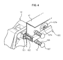
- FIG. 4 is a partially sectional perspective view illustrating a coupling relationship between a first delivery unit and a second delivery unit provided in the image forming apparatus according to an embodiment of the present general inventive concept
- FIGS. 5 and 6 are sectional views illustrating coupling/separating operations of the first delivery unit provided in the image forming apparatus according to an embodiment of the present general inventive concept.
- an image forming apparatus can include, arranged in a body 10 defining the external appearance of the apparatus, a feed unit 20 to supply a printing medium P such as paper, an exposure unit 30 to irradiate light containing image information, a developing unit 40 to develop a visible image via the light irradiated from the exposure unit 30 , a transfer unit 50 to transfer the visible image, developed by the developing unit 40 , to the printing medium P, a fixing unit 60 to fix the visible image on the printing medium P by applying heat and pressure to the printing medium P, and a discharge unit 70 to discharge the printing medium P, on which an image can be completely formed, out of the body 10 .
- a feed unit 20 to supply a printing medium P such as paper
- an exposure unit 30 to irradiate light containing image information
- a developing unit 40 to develop a visible image via the light irradiated from the exposure unit 30
- a transfer unit 50 to transfer the visible image, developed by the developing unit 40 , to the printing medium P
- the feed unit 20 can include a tray 21 in which the printing media P can be loaded, and a pickup roller 22 to pick up the printing media P, loaded in the tray 21 , sheet by sheet.
- the printing medium P, picked-up by the pickup roller 22 can be delivered to the transfer unit 50 by a delivery roller 11 installed in the body 10 .
- the exposure unit 30 can irradiate light to photoconductors 41 of the developing unit 40 before the printing medium P enters the transfer unit 50 .
- photoconductors 41 Y, 41 M, 41 C and 41 K can serve as image carriers on which a toner image is present.
- the photoconductors 41 Y, 41 M, 41 C and 41 K can correspond, respectively, to developer containers 42 Y, 42 M, 42 C and 42 K which can be arranged vertically in parallel, each of the photoconductors 41 Y, 41 M, 41 C and 41 K being formed at a surface thereof with an electrostatic latent image by the light irradiated from the exposure unit 30 .
- the present general inventive concept is not limited to such arrangement, and other arrangements may be used without departing from the broader principles and spirit of the present general inventive concept.
- the plurality of developer containers 42 Y, 42 M, 42 C and 42 K of the developing unit 40 can be used to receive yellow, magenta, cyan and black toners, respectively.
- the image forming apparatus according to an example embodiment can be of a tandem type and thus, the respective developer containers 42 Y, 42 M, 42 C and 42 K can be arranged vertically in parallel.
- the respective developer containers 42 Y, 42 M, 42 C and 42 K can correspond to the respective photoconductors 41 Y, 41 M, 41 C and 41 K.
- Each of the developer containers 42 Y, 42 M, 42 C and 42 K can be provided with a feed roller 43 and a developing roller 44 to feed the toners to the photoconductors 41 Y, 41 M, 41 C and 41 K.
- the fixing unit 60 can include a heating roller 62 in which a heater 61 is received, a press roller 63 to press the printing medium P to the heating roller 62 , and a fixing motor 64 to generate and transmit a rotating force to at least one of the heating roller 62 to press roller 63 so as to rotate the roller.
- the printing medium P onto which a toner image is transferred while passing through the transfer unit 50 , can be delivered to the fixing unit 60 .
- the toner image transferred onto the printing medium P can be fixed to the printing medium P.
- the discharge unit 70 can include a discharge roller 71 to discharge the printing medium P out of the body 10 via rotation thereof.
- the printing medium P having passed through the fixing unit 60 , can be discharged out of the body 10 by passing through the discharge roller 71 .
- a rotating force from the fixing motor 64 can be transmitted to the discharge roller 71 via a plurality of discharge gears, to allow the discharge roller 71 to discharge the printing medium P via rotation thereof.
- the transfer unit 50 can perform overlap transfer of the visible images on the photoconductors 41 Y, 41 M, 41 C and 41 K, to transfer a resulting overlapped image on the printing medium P.
- electrostatic latent images can be formed on surfaces of the photoconductors 41 Y, 41 M, 41 C and 41 K by the exposure unit 30 , and the toners can be fed to the electrostatic latent images so as to develop visible images.
- the visible images developed on the photoconductors 41 Y, 41 M, 41 C and 41 K can be transferred to and overlapped on an intermediate transfer member 51 which can be rotated in contact with the photoconductors 41 Y, 41 M, 41 C and 41 K so as to form a color image.
- the intermediate transfer member 51 can be provided as an image carrier on which the toner images are present.
- the intermediate transfer member 51 can be embodied as an intermediate transfer belt 51 a .
- the intermediate transfer belt 51 a on which the color image is formed, can transfer the image to the printing medium P, so as to form the resulting toner image on the printing medium P.
- the intermediate transfer belt 51 a can be provided with a transfer motor 55 to generate a rotating force required to rotate the intermediate transfer belt 51 a .
- the intermediate transfer belt 51 a can maintain a tensile force by intermediate transfer belt rollers 52 and transfer rollers 53 and 54 during implementation of a transfer operation.
- the intermediate transfer belt rollers 52 can provide the intermediate transfer belt 51 a with a tensile force in contact with the intermediate transfer belt 51 a .
- the intermediate transfer belt rollers 52 can include first, second and third intermediate transfer belt rollers 52 a , 52 b and 52 c .
- the first, second and third intermediate transfer belt rollers 52 a , 52 b and 52 c can come into outward contact with an inner surface of the intermediate transfer belt 51 a to maintain the intermediate transfer belt 51 a in a tightly tensioned state.
- the transfer motor 55 can be connected with the third intermediate transfer belt roller 52 c via a plurality of transfer gears 56 a , 56 b and 56 c .
- the intermediate transfer belt 51 a can be rotated around the first, second and third intermediate transfer belt rollers 52 a , 52 b and 52 c , so as to perform a transfer operation.
- the transfer rollers 53 and 54 can include first transfer rollers 53 Y, 53 M, 53 C and 53 K to press the intermediate transfer belt 51 a to the photoconductors 41 Y, 41 M, 41 C and 41 K, and a second transfer roller 54 in contact with the third intermediate transfer belt roller 52 c with the intermediate transfer belt 51 a interposed therebetween.
- the first transfer rollers 53 Y, 53 M, 53 C and 53 K can press the intermediate transfer belt 51 a to the respective photoconductors 41 Y, 41 M, 41 C and 41 K, so as to transfer the visible images from the photoconductors 41 Y, 41 M, 41 C and 41 K to the intermediate transfer belt 51 a .
- the second transfer roller 54 can press the intermediate transfer belt 51 a to correspond to the third intermediate transfer belt roller 52 c , so as to transfer the overlapped image from the intermediate transfer belt 51 a to the printing medium P.
- the transfer unit 50 further can include a cleaning blade 57 to separate waste toner remaining on the intermediate transfer belt 51 a , and a waste toner collector 58 in which the waste toner separated by the cleaning blade 57 can be received. Accordingly, after completing the transfer of toners to the printing medium P, the waste toner remaining on the intermediate transfer belt 51 a can be separated by the cleaning blade 57 , and can be collected in the waste toner collector 58 .
- the image forming apparatus can be provided with a waste toner recovery device 800 .
- the waste toner recovery device 800 can serve to recover the waste toner, which can be separated from the intermediate transfer belt 51 a , as the image carrier, after completing the transfer of toners to the printing medium P in the transfer unit 50 and is collected in the waste toner collector 58 .
- the waste toner recovery device 800 can include a first delivery unit 810 , a second delivery unit 820 , and a waste toner cartridge 830 .
- the first delivery unit 810 can be installed in the waste toner collector 58 and can extend over a large distance in the same first direction as a width direction of the intermediate transfer belt 51 a , to deliver the waste toner, collected in the waste toner collector 58 , along the first direction.
- the second delivery unit 820 can be used to redeliver the waste toner, delivered by the first delivery unit 810 , along a second direction perpendicular to the first direction.
- the waste toner cartridge 830 can receive the waste toner delivered by the second delivery unit 820 .
- the first delivery unit 810 can include a delivery screw 811 , which can be disposed in the waste toner collector 58 and can extend over a large distance in the first direction, to deliver the waste toner collected in the waste toner collector 58 along the first direction.
- the second delivery unit 820 can include a delivery belt 821 to be rotated upon receiving a rotating force transmitted via the delivery screw 811 , and a driving pulley 822 and driven pulley 823 installed at opposite inner sides of the delivery belt 821 to enable rotation of the delivery belt 821 .
- the delivery screw 811 can be formed at an outer circumference thereof with a first spiral thread 811 a .
- the driving pulley 822 can be integrally formed with the delivery belt 821 to protrude laterally from the delivery belt 821 and can be formed at an outer circumference thereof with a second spiral thread 822 a to deliver the waste toner from the first spiral thread 811 a.
- the first delivery unit 810 can be connected with the fixing motor 64 , which can have less effect on the quality of an image, via a plurality of gears, to receive a rotating force from the fixing motor 64 .
- the second delivery unit 820 can be adapted to be operated by the rotating force from the first delivery unit 810 . That is, the second delivery unit 820 can be operated upon receiving the rotating force from the first delivery unit 810 without a separate drive source, enabling a more simplified configuration of the waste toner recovery device 800 .
- the driving pulley 822 of the second delivery unit 820 can be connected to the delivery screw 811 of the first delivery unit 810 . Accordingly, the driving pulley 822 can be rotated by the rotating force transmitted through the delivery screw 811 , thereby serving to rotate the delivery belt 821 .
- the delivery screw 811 and driving pulley 822 can be formed with a coupling recess 811 b and a coupling protrusion 822 b to be engaged with each other.
- the coupling recess 811 b and coupling protrusion 822 b can have corresponding shapes and can be arranged opposite each other.
- the delivery screw 811 can include the indented coupling recess 811 b , into which the coupling protrusion 822 b can be inserted, and the driving pulley 822 can include the coupling protrusion 822 b to be inserted into the coupling recess 811 b.
- the waste toner in the waste toner collector 58 can move toward the delivery belt 821 to thereby be transmitted to the delivery belt 821 . If the waste toner transmitted to the delivery belt 821 is again guided to the waste toner cartridge 830 by the delivery belt 821 , recovery of the waste toner from the transfer unit 50 can be completed.
- the first delivery unit 810 of the image forming apparatus can be installed immediately above the transfer unit 50
- the second delivery unit 820 can be installed at one end of the first delivery unit 810 so as to protrude laterally from the transfer unit 50
- a frame 12 to which the transfer unit 50 , developer containers 42 Y, 42 M, 42 C and 42 K and other various elements are installed can be installed in the body 10 such that the frame 12 is spaced apart from an inner side surface of the body 10 .
- the transfer unit 50 , developer containers 42 Y, 42 M, 42 C and 42 K and the like may be installed inside the frame 12 , and a variety of elements may be installed in a space between the body 10 and the frame 12 .
- the transfer unit 50 is installed in a space inside the frame 12 in a state wherein the second delivery unit 820 is coupled to the first delivery unit 810 that is in turn coupled to the transfer unit 50 to allow the second delivery unit 820 to be introduced into the space inside the frame 12 , it may be possible to provide an additional space to introduce the second delivery unit 820 at a lateral side of the transfer unit 50 . This can consequently be provided by an increase in a width of the body 10 .
- the second delivery unit 820 can be detachably coupled to the first delivery unit 810 in a space between the body 10 and the frame 12 to achieve a compact size of the body 10 .
- the second delivery unit 820 can be installed in a space between the body 10 and the frame 12 , and the transfer unit 50 , to which the first delivery unit 810 is installed, can be installed in a space inside the frame 12 .
- the transfer unit 50 to which the first delivery unit 810 is installed, can be installed in a space inside the frame 12 .
- the second delivery unit 820 can be movable in the same first direction as a longitudinal direction of the first delivery unit 810 such that it can be coupled to or detached from the first delivery unit 810 via movements thereof in the first direction.
- the frame 12 can be integrally formed with guide rods 13 extending in the first direction, and the second delivery unit 820 can be movably installed to the guide rods 13 .
- the second delivery unit 820 can have guide portions 824 having guide holes 824 a to enable movable installation of the guide rods 13 .
- plural pairs of upper and lower guide rods 13 can be spaced apart from one another in the second direction, and a plurality of guide portions 824 can extend upward and downward from the second delivery unit 820 to correspond to the guide rods 13 .
- a rotating cam 825 can be rotatably installed in the body 10 , for example, to the frame 12 , to move the second delivery unit 820 in the first direction.
- the rotating cam 825 can be formed at a surface thereof with cam faces 825 a and 825 b and can include a mount portion 825 a and a valley portion 825 b which can be circumferentially spaced apart from each other and can be connected to each other via a slope.
- One side of the second delivery unit 820 can be supported at the cam faces 825 a and 825 b .
- the second delivery unit 820 can be reciprocally moved in the first direction as it is moved along the cam faces 825 a and 825 b according to a rotation of the rotating cam 825 .
- the rotating cam 825 can be integrally formed with a lever ( 825 c , See FIG. 5 ) for easy transmission of an external force.
- Each guide rod 13 can be installed with an elastic member 826 to press the second delivery unit 820 toward the first delivery unit 810 .
- the elastic member 826 can be a coil spring provided at the exterior of the guide rod 13 . Accordingly, as one end of the elastic member 826 is supported by a bolt 827 fastened to a tip end of the guide rod 13 and the other end of the elastic member 826 is supported by the guide portion 824 , the second delivery unit 820 can be elastically supported toward the first delivery unit 810 .
- the second delivery unit 820 can be supported by the mount portion 825 a of the cam faces 825 a and 825 b of the rotating cam 825 . Thereby, the second delivery unit 820 can be kept at a laterally moved position. Thereafter, if the second delivery unit 820 is supported by the valley portion 825 b of the cam faces 825 a and 825 b of the rotating cam 825 as illustrated in FIG.
- the second delivery unit 820 can be moved toward the first delivery unit 810 by an elastic force of the elastic member 826 .
- the coupling protrusion 822 a which is formed at the driving pulley 822 of the second delivery unit 820 can be coupled into the coupling recess 811 b formed in the delivery screw 811 of the first delivery unit 810 , allowing the second delivery unit 820 to receive a rotating force from the first delivery unit 810 .
- the image forming apparatus of the present general inventive concept is designed to recover the waste toner collected from the intermediate transfer belt 51 a by use of the waste toner recovery device 800
- the present general inventive concept is not limited thereto, and can also be applicable to other image forming apparatuses, for example, wherein the toner is directly transferred from a photoconductor to a printing medium such that waste toner collected from the photoconductor can be recovered via a waste toner recovery device.
- an image forming apparatus can have an enhanced space utility by virtue of a waste toner recovery device configured as described above, resulting in a compact body size.
Landscapes
- Physics & Mathematics (AREA)
- General Physics & Mathematics (AREA)
- Life Sciences & Earth Sciences (AREA)
- Engineering & Computer Science (AREA)
- Environmental & Geological Engineering (AREA)
- Sustainable Development (AREA)
- Electrostatic Charge, Transfer And Separation In Electrography (AREA)
- Electrophotography Configuration And Component (AREA)
Abstract
Description
- This application claims the benefit of Korean Patent Application No. 2008-0082341, filed on Aug. 22, 2008 in the Korean Intellectual Property Office, the disclosure of which is incorporated herein by reference in its entirety.
- 1. Field of the Invention
- The present general inventive concept relates to an image forming apparatus, and, more particularly, to an image forming apparatus having a waste toner recovery device to collect waste toner.
- 2. Description of the Related Art
- An image forming apparatus is an apparatus to form an image on a printing medium, such as paper, according to input image signals. Examples of the image forming apparatus include printers, copiers, facsimiles, and devices combining functions thereof.
- The image forming apparatus to form an image on a printing medium includes, arranged in a body defining the external appearance of the apparatus, an exposure unit to irradiate light containing image information, a developing unit to develop a visible image via the light irradiated from the exposure unit, a transfer unit to transfer the visible image developed by the developing unit to the printing medium, a fixing unit to fix the visible image on the printing medium by applying heat and pressure to the printing medium, and a discharge unit to discharge the printing medium, on which an image is completely formed, out of the body.
- Recently, an image forming apparatus having a waste toner recovery device to collect waste toner accumulated on an image carrier, on which a toner image is formed, such as the transfer unit, has been disclosed. The size of the image forming apparatus is affected by a configuration of the waste toner recovery device and therefore, it is possible to appropriately select a configuration and arrangement of the waste toner recovery device, for a more compact size of the image forming apparatus.
- Example embodiments of the present general inventive concept provide an image forming apparatus having an improved configuration of a waste toner recovery device to achieve a more compact body size.
- Additional embodiments of the present general inventive concept will be set forth in part in the description which follows and, in part, will be obvious from the description, or may be learned by practice of the general inventive concept.
- Example embodiments of the present general inventive concept provide an image forming apparatus including a body, a frame installed in the body, an image carrier installed inside the frame, and a waste toner recovery device to recover waste toner collected from the image carrier, wherein the waste toner recovery device can include a first delivery unit to deliver the waste toner in a first direction, and a second delivery unit to deliver the waste toner delivered from the first delivery unit in a second direction, wherein the second delivery unit can be movably installed to the frame and can be coupled to or detached from the first delivery unit via movement thereof.
- The second delivery unit may be installed at an outside of the frame.
- The image forming apparatus may further include a guide rod extending in the first direction from the frame to guide movement of the second delivery unit, and a guide portion extending from the second delivery unit and formed with a guide hole to install the guide rod.
- The image forming apparatus may further include a rotating cam disposed at one side of the second delivery unit to move the second delivery unit via rotation thereof.
- The image forming apparatus may further include an elastic member to press the second delivery unit toward the first delivery unit.
- The first delivery unit may include a delivery screw to deliver the waste toner via rotation thereof, and the second delivery unit can include a delivery belt to deliver the waste toner delivered via the delivery screw.
- The second delivery unit may further include a driving pulley and a driven pulley installed at opposite inner sides of the delivery belt, and the driving pulley may be coupled with the delivery screw to receive a rotating force from the delivery screw.
- The delivery screw and driving pulley may be formed with a coupling recess and a coupling protrusion, respectively, which can be coupled with each other to transmit the rotating force of the delivery screw to the driving pulley.
- The image forming apparatus may further include a transfer unit including the image carrier and installed inside the frame, and the first delivery unit may deliver the waste toner collected from the transfer unit.
- Example embodiments of the present general inventive concept also provide an image forming apparatus including a body, a frame installed in the body, a transfer unit installed inside the frame, and a waste toner recovery device to recover waste toner collected from the transfer unit, wherein the waste toner recovery device can include a waste toner cartridge in which the waste toner is stored, and a delivery unit movably installed between the body and the frame so as to be coupled to or separated from the transfer unit via movement thereof.
- Example embodiments of the present general inventive concept can also provide a waste toner recovery device of an image forming device, including a first delivery unit disposed along a width direction of a transfer unit of the image forming device to recover waste toner therefrom, and a second delivery unit disposed at a first end of the first delivery unit perpendicular to the transfer unit to deliver the waste toner in the perpendicular direction to a storage unit via a rotational force transmitted from the first delivery unit.
- The first delivery unit may include a delivery screw to transmit the rotational force to the second delivery unit.
- The second delivery unit may include a delivery belt to receive the rotational force from the delivery screw and to deliver the waste toner to the storage unit.
- The image forming device may include a fixing motor connected to another end of the first delivery unit to generate the rotational force of the first delivery unit.
- The second delivery unit may be detachably coupled to the first delivery unit upon rotation of a cam connected to the second delivery unit.
- The second delivery unit may include a driving pulley to drive the delivery belt, the driving pulley having a second delivery screw connected to the delivery screw to deliver the waste toner from the delivery screw to the delivery belt.
- These and/or other example embodiments of the present general inventive concept will become apparent and more readily appreciated from the following description of the embodiments, taken in conjunction with the accompanying drawings of which:
-
FIG. 1 is a sectional view illustrating an image forming apparatus according to an embodiment of the present general inventive concept; -
FIG. 2 is a perspective view illustrating a transfer unit and a waste toner recovery device provided in the image forming apparatus according to an embodiment of the present general inventive concept; -
FIG. 3 is an exploded perspective view illustrating an interior configuration of the waste toner recovery device provided in the image forming apparatus according to an embodiment of the present general inventive concept; -
FIG. 4 is a partially sectional perspective view illustrating a coupling relationship between a first delivery unit and a second delivery unit provided in the image forming apparatus according to an embodiment of the present general inventive concept; and -
FIGS. 5 and 6 are sectional views illustrating coupling/separating operations of the first delivery unit provided in the image forming apparatus according to an embodiment of the present general inventive concept. - Reference will now be made in detail to exemplary embodiments of the present general inventive concept, examples of which are illustrated in the accompanying drawings, wherein like reference numerals refer to the like elements throughout. The embodiments are described below to explain the present general inventive concept by referring to the figures.
- As illustrated in
FIG. 1 , an image forming apparatus according to an example embodiment can include, arranged in abody 10 defining the external appearance of the apparatus, afeed unit 20 to supply a printing medium P such as paper, anexposure unit 30 to irradiate light containing image information, a developingunit 40 to develop a visible image via the light irradiated from theexposure unit 30, atransfer unit 50 to transfer the visible image, developed by the developingunit 40, to the printing medium P, afixing unit 60 to fix the visible image on the printing medium P by applying heat and pressure to the printing medium P, and a discharge unit 70 to discharge the printing medium P, on which an image can be completely formed, out of thebody 10. - The
feed unit 20 can include atray 21 in which the printing media P can be loaded, and apickup roller 22 to pick up the printing media P, loaded in thetray 21, sheet by sheet. The printing medium P, picked-up by thepickup roller 22, can be delivered to thetransfer unit 50 by adelivery roller 11 installed in thebody 10. - The
exposure unit 30 can irradiate light to photoconductors 41 of the developingunit 40 before the printing medium P enters thetransfer unit 50. In the example embodiments,photoconductors photoconductors developer containers photoconductors exposure unit 30. However, the present general inventive concept is not limited to such arrangement, and other arrangements may be used without departing from the broader principles and spirit of the present general inventive concept. - The plurality of
developer containers unit 40 can be used to receive yellow, magenta, cyan and black toners, respectively. The image forming apparatus according to an example embodiment can be of a tandem type and thus, therespective developer containers respective developer containers respective photoconductors developer containers feed roller 43 and a developingroller 44 to feed the toners to thephotoconductors - The
fixing unit 60 can include aheating roller 62 in which aheater 61 is received, apress roller 63 to press the printing medium P to theheating roller 62, and afixing motor 64 to generate and transmit a rotating force to at least one of theheating roller 62 to pressroller 63 so as to rotate the roller. The printing medium P, onto which a toner image is transferred while passing through thetransfer unit 50, can be delivered to thefixing unit 60. As heat and pressure are applied to the printing medium P passing between theheating roller 62 and thepress roller 63 of thefixing unit 60, the toner image transferred onto the printing medium P can be fixed to the printing medium P. - The discharge unit 70 can include a
discharge roller 71 to discharge the printing medium P out of thebody 10 via rotation thereof. The printing medium P, having passed through thefixing unit 60, can be discharged out of thebody 10 by passing through thedischarge roller 71. In the present example embodiment, a rotating force from thefixing motor 64 can be transmitted to thedischarge roller 71 via a plurality of discharge gears, to allow thedischarge roller 71 to discharge the printing medium P via rotation thereof. - The
transfer unit 50 can perform overlap transfer of the visible images on thephotoconductors photoconductors exposure unit 30, and the toners can be fed to the electrostatic latent images so as to develop visible images. The visible images developed on thephotoconductors intermediate transfer member 51 which can be rotated in contact with thephotoconductors intermediate transfer member 51 can be provided as an image carrier on which the toner images are present. In the present example embodiment, theintermediate transfer member 51 can be embodied as anintermediate transfer belt 51 a. Theintermediate transfer belt 51 a, on which the color image is formed, can transfer the image to the printing medium P, so as to form the resulting toner image on the printing medium P. Theintermediate transfer belt 51 a can be provided with atransfer motor 55 to generate a rotating force required to rotate theintermediate transfer belt 51 a. Theintermediate transfer belt 51 a can maintain a tensile force by intermediate transfer belt rollers 52 andtransfer rollers 53 and 54 during implementation of a transfer operation. - The intermediate transfer belt rollers 52 can provide the
intermediate transfer belt 51 a with a tensile force in contact with theintermediate transfer belt 51 a. The intermediate transfer belt rollers 52 can include first, second and third intermediatetransfer belt rollers transfer belt rollers intermediate transfer belt 51 a to maintain theintermediate transfer belt 51 a in a tightly tensioned state. In the present example embodiment, thetransfer motor 55 can be connected with the third intermediatetransfer belt roller 52 c via a plurality of transfer gears 56 a, 56 b and 56 c. Accordingly, as a rotating force generated from thetransfer motor 55 is transmitted to the thirdtransfer belt roller 52 c via the transfer gears 56 a, 56 b and 56 c, theintermediate transfer belt 51 a can be rotated around the first, second and third intermediatetransfer belt rollers - The
transfer rollers 53 and 54 can includefirst transfer rollers intermediate transfer belt 51 a to thephotoconductors second transfer roller 54 in contact with the third intermediatetransfer belt roller 52 c with theintermediate transfer belt 51 a interposed therebetween. Thefirst transfer rollers intermediate transfer belt 51 a to therespective photoconductors photoconductors intermediate transfer belt 51 a. Thesecond transfer roller 54 can press theintermediate transfer belt 51 a to correspond to the third intermediatetransfer belt roller 52 c, so as to transfer the overlapped image from theintermediate transfer belt 51 a to the printing medium P. - The
transfer unit 50 further can include acleaning blade 57 to separate waste toner remaining on theintermediate transfer belt 51 a, and awaste toner collector 58 in which the waste toner separated by thecleaning blade 57 can be received. Accordingly, after completing the transfer of toners to the printing medium P, the waste toner remaining on theintermediate transfer belt 51 a can be separated by thecleaning blade 57, and can be collected in thewaste toner collector 58. - The image forming apparatus, as illustrated in
FIG. 2 , can be provided with a wastetoner recovery device 800. The wastetoner recovery device 800 can serve to recover the waste toner, which can be separated from theintermediate transfer belt 51 a, as the image carrier, after completing the transfer of toners to the printing medium P in thetransfer unit 50 and is collected in thewaste toner collector 58. The wastetoner recovery device 800 can include afirst delivery unit 810, asecond delivery unit 820, and awaste toner cartridge 830. Thefirst delivery unit 810 can be installed in thewaste toner collector 58 and can extend over a large distance in the same first direction as a width direction of theintermediate transfer belt 51 a, to deliver the waste toner, collected in thewaste toner collector 58, along the first direction. Thesecond delivery unit 820 can be used to redeliver the waste toner, delivered by thefirst delivery unit 810, along a second direction perpendicular to the first direction. Thewaste toner cartridge 830 can receive the waste toner delivered by thesecond delivery unit 820. - As illustrated in
FIG. 3 , thefirst delivery unit 810 can include adelivery screw 811, which can be disposed in thewaste toner collector 58 and can extend over a large distance in the first direction, to deliver the waste toner collected in thewaste toner collector 58 along the first direction. Thesecond delivery unit 820 can include adelivery belt 821 to be rotated upon receiving a rotating force transmitted via thedelivery screw 811, and a drivingpulley 822 and drivenpulley 823 installed at opposite inner sides of thedelivery belt 821 to enable rotation of thedelivery belt 821. Thedelivery screw 811 can be formed at an outer circumference thereof with afirst spiral thread 811 a. The drivingpulley 822 can be integrally formed with thedelivery belt 821 to protrude laterally from thedelivery belt 821 and can be formed at an outer circumference thereof with asecond spiral thread 822 a to deliver the waste toner from thefirst spiral thread 811 a. - The
first delivery unit 810 can be connected with the fixingmotor 64, which can have less effect on the quality of an image, via a plurality of gears, to receive a rotating force from the fixingmotor 64. Thesecond delivery unit 820 can be adapted to be operated by the rotating force from thefirst delivery unit 810. That is, thesecond delivery unit 820 can be operated upon receiving the rotating force from thefirst delivery unit 810 without a separate drive source, enabling a more simplified configuration of the wastetoner recovery device 800. - The driving
pulley 822 of thesecond delivery unit 820 can be connected to thedelivery screw 811 of thefirst delivery unit 810. Accordingly, the drivingpulley 822 can be rotated by the rotating force transmitted through thedelivery screw 811, thereby serving to rotate thedelivery belt 821. To transmit the rotating force of thedelivery screw 811 to the drivingpulley 822, thedelivery screw 811 and drivingpulley 822 can be formed with acoupling recess 811 b and acoupling protrusion 822 b to be engaged with each other. Thecoupling recess 811 b andcoupling protrusion 822 b can have corresponding shapes and can be arranged opposite each other. In the present example embodiment, thedelivery screw 811 can include theindented coupling recess 811 b, into which thecoupling protrusion 822 b can be inserted, and the drivingpulley 822 can include thecoupling protrusion 822 b to be inserted into thecoupling recess 811 b. - Accordingly, as the
delivery screw 811 b is rotated upon receiving the rotating force transmitted from the fixingmotor 64, the waste toner in thewaste toner collector 58 can move toward thedelivery belt 821 to thereby be transmitted to thedelivery belt 821. If the waste toner transmitted to thedelivery belt 821 is again guided to thewaste toner cartridge 830 by thedelivery belt 821, recovery of the waste toner from thetransfer unit 50 can be completed. - The
first delivery unit 810 of the image forming apparatus according to the example embodiments can be installed immediately above thetransfer unit 50, and thesecond delivery unit 820 can be installed at one end of thefirst delivery unit 810 so as to protrude laterally from thetransfer unit 50. As illustrated inFIG. 4 , aframe 12, to which thetransfer unit 50,developer containers body 10 such that theframe 12 is spaced apart from an inner side surface of thebody 10. For example, thetransfer unit 50,developer containers frame 12, and a variety of elements may be installed in a space between thebody 10 and theframe 12. - Accordingly, in the case where the
transfer unit 50 is installed in a space inside theframe 12 in a state wherein thesecond delivery unit 820 is coupled to thefirst delivery unit 810 that is in turn coupled to thetransfer unit 50 to allow thesecond delivery unit 820 to be introduced into the space inside theframe 12, it may be possible to provide an additional space to introduce thesecond delivery unit 820 at a lateral side of thetransfer unit 50. This can consequently be provided by an increase in a width of thebody 10. - In the image forming apparatus according to example embodiments of the present general inventive concept, the
second delivery unit 820 can be detachably coupled to thefirst delivery unit 810 in a space between thebody 10 and theframe 12 to achieve a compact size of thebody 10. - For example, the
second delivery unit 820 can be installed in a space between thebody 10 and theframe 12, and thetransfer unit 50, to which thefirst delivery unit 810 is installed, can be installed in a space inside theframe 12. With this configuration, no space for installation of thesecond delivery unit 820 inside theframe 12 is required, and consequently, thebody 10 can achieve a more compact size. - In the present example embodiment, the
second delivery unit 820 can be movable in the same first direction as a longitudinal direction of thefirst delivery unit 810 such that it can be coupled to or detached from thefirst delivery unit 810 via movements thereof in the first direction. For this, theframe 12 can be integrally formed withguide rods 13 extending in the first direction, and thesecond delivery unit 820 can be movably installed to theguide rods 13. Thesecond delivery unit 820 can haveguide portions 824 havingguide holes 824a to enable movable installation of theguide rods 13. For example, plural pairs of upper andlower guide rods 13 can be spaced apart from one another in the second direction, and a plurality ofguide portions 824 can extend upward and downward from thesecond delivery unit 820 to correspond to theguide rods 13. - To move the
second delivery unit 820 in the first direction, arotating cam 825 can be rotatably installed in thebody 10, for example, to theframe 12, to move thesecond delivery unit 820 in the first direction. Therotating cam 825 can be formed at a surface thereof with cam faces 825 a and 825 b and can include amount portion 825 a and avalley portion 825 b which can be circumferentially spaced apart from each other and can be connected to each other via a slope. One side of thesecond delivery unit 820 can be supported at the cam faces 825 a and 825 b. Accordingly, thesecond delivery unit 820 can be reciprocally moved in the first direction as it is moved along the cam faces 825 a and 825 b according to a rotation of therotating cam 825. Therotating cam 825 can be integrally formed with a lever (825 c, SeeFIG. 5 ) for easy transmission of an external force. - Each
guide rod 13 can be installed with anelastic member 826 to press thesecond delivery unit 820 toward thefirst delivery unit 810. In the present example embodiment, theelastic member 826 can be a coil spring provided at the exterior of theguide rod 13. Accordingly, as one end of theelastic member 826 is supported by abolt 827 fastened to a tip end of theguide rod 13 and the other end of theelastic member 826 is supported by theguide portion 824, thesecond delivery unit 820 can be elastically supported toward thefirst delivery unit 810. - Accordingly, prior to installing the
transfer unit 50, as illustrated inFIG. 5 , to allow thetransfer unit 50 to be introduced into a space inside theframe 12, thesecond delivery unit 820 can be supported by themount portion 825 a of the cam faces 825 a and 825 b of therotating cam 825. Thereby, thesecond delivery unit 820 can be kept at a laterally moved position. Thereafter, if thesecond delivery unit 820 is supported by thevalley portion 825 b of the cam faces 825 a and 825 b of therotating cam 825 as illustrated inFIG. 6 as the rotatingcam 825 can be rotated after completing the installation of thetransfer unit 50, thesecond delivery unit 820 can be moved toward thefirst delivery unit 810 by an elastic force of theelastic member 826. Thereby, thecoupling protrusion 822 a which is formed at the drivingpulley 822 of thesecond delivery unit 820 can be coupled into thecoupling recess 811 b formed in thedelivery screw 811 of thefirst delivery unit 810, allowing thesecond delivery unit 820 to receive a rotating force from thefirst delivery unit 810. - Although the image forming apparatus of the present general inventive concept is designed to recover the waste toner collected from the
intermediate transfer belt 51 a by use of the wastetoner recovery device 800, the present general inventive concept is not limited thereto, and can also be applicable to other image forming apparatuses, for example, wherein the toner is directly transferred from a photoconductor to a printing medium such that waste toner collected from the photoconductor can be recovered via a waste toner recovery device. - As is apparent from the above description, an image forming apparatus according to an example embodiment can have an enhanced space utility by virtue of a waste toner recovery device configured as described above, resulting in a compact body size.
- Although a few example embodiments of the present general inventive concept have been illustrated and described, it will be appreciated by those skilled in the art that changes may be made in these example embodiments without departing from the principles and spirit of the general inventive concept, the scope of which is defined in the claims and their equivalents.
Claims (20)
Applications Claiming Priority (3)
| Application Number | Priority Date | Filing Date | Title |
|---|---|---|---|
| KR10-2008-0082341 | 2008-08-22 | ||
| KR1020080082341A KR101502116B1 (en) | 2008-08-22 | 2008-08-22 | The image forming apparatus |
| KR2008-82341 | 2008-08-22 |
Publications (2)
| Publication Number | Publication Date |
|---|---|
| US20100046999A1 true US20100046999A1 (en) | 2010-02-25 |
| US8903299B2 US8903299B2 (en) | 2014-12-02 |
Family
ID=41696531
Family Applications (1)
| Application Number | Title | Priority Date | Filing Date |
|---|---|---|---|
| US12/542,216 Active 2031-07-31 US8903299B2 (en) | 2008-08-22 | 2009-08-17 | Image forming apparatus and a waste toner recovery device thereof |
Country Status (2)
| Country | Link |
|---|---|
| US (1) | US8903299B2 (en) |
| KR (1) | KR101502116B1 (en) |
Cited By (5)
| Publication number | Priority date | Publication date | Assignee | Title |
|---|---|---|---|---|
| US8948676B2 (en) * | 2010-07-21 | 2015-02-03 | Ricoh Company, Ltd. | Image forming apparatus |
| US20160154341A1 (en) * | 2014-11-28 | 2016-06-02 | Canon Kabushiki Kaisha | Conveying device, cleaning device, developing device, process cartridge and image forming apparatus |
| CN105652627A (en) * | 2014-11-28 | 2016-06-08 | 佳能株式会社 | Conveying equipment, cleaning equipment, developing equipment, process cartridges, and image forming devices |
| JP2018155959A (en) * | 2017-03-17 | 2018-10-04 | ブラザー工業株式会社 | Process cartridge |
| JP2019194653A (en) * | 2018-05-02 | 2019-11-07 | キヤノン株式会社 | Image forming apparatus |
Citations (5)
| Publication number | Priority date | Publication date | Assignee | Title |
|---|---|---|---|---|
| US5398098A (en) * | 1993-01-26 | 1995-03-14 | Sharp Kabushiki Kaisha | Image forming apparatus |
| US5587769A (en) * | 1994-11-11 | 1996-12-24 | Minolta Co., Ltd. | Image forming apparatus allowing simple replacement of intermediate transfer member and easy maintenance and handling of paper jams |
| US20070081839A1 (en) * | 2005-10-12 | 2007-04-12 | Samsung Electronics Co., Ltd. | Toner conveying unit and electrophotographic image forming apparatus using the conveying unit |
| US20080138133A1 (en) * | 2006-12-08 | 2008-06-12 | Ricoh Company, Limited | Transfer device, image forming apparatus, and waste toner container |
| US20090010694A1 (en) * | 2007-07-02 | 2009-01-08 | Samsung Electronics Co., Ltd. | Developing device, waste toner collecting device and image forming apparatus having the same |
Family Cites Families (1)
| Publication number | Priority date | Publication date | Assignee | Title |
|---|---|---|---|---|
| JP4794849B2 (en) | 2004-11-15 | 2011-10-19 | 京セラミタ株式会社 | Waste toner transport mechanism of image forming apparatus |
-
2008
- 2008-08-22 KR KR1020080082341A patent/KR101502116B1/en not_active Expired - Fee Related
-
2009
- 2009-08-17 US US12/542,216 patent/US8903299B2/en active Active
Patent Citations (5)
| Publication number | Priority date | Publication date | Assignee | Title |
|---|---|---|---|---|
| US5398098A (en) * | 1993-01-26 | 1995-03-14 | Sharp Kabushiki Kaisha | Image forming apparatus |
| US5587769A (en) * | 1994-11-11 | 1996-12-24 | Minolta Co., Ltd. | Image forming apparatus allowing simple replacement of intermediate transfer member and easy maintenance and handling of paper jams |
| US20070081839A1 (en) * | 2005-10-12 | 2007-04-12 | Samsung Electronics Co., Ltd. | Toner conveying unit and electrophotographic image forming apparatus using the conveying unit |
| US20080138133A1 (en) * | 2006-12-08 | 2008-06-12 | Ricoh Company, Limited | Transfer device, image forming apparatus, and waste toner container |
| US20090010694A1 (en) * | 2007-07-02 | 2009-01-08 | Samsung Electronics Co., Ltd. | Developing device, waste toner collecting device and image forming apparatus having the same |
Cited By (11)
| Publication number | Priority date | Publication date | Assignee | Title |
|---|---|---|---|---|
| US8948676B2 (en) * | 2010-07-21 | 2015-02-03 | Ricoh Company, Ltd. | Image forming apparatus |
| US20160154341A1 (en) * | 2014-11-28 | 2016-06-02 | Canon Kabushiki Kaisha | Conveying device, cleaning device, developing device, process cartridge and image forming apparatus |
| CN105652627A (en) * | 2014-11-28 | 2016-06-08 | 佳能株式会社 | Conveying equipment, cleaning equipment, developing equipment, process cartridges, and image forming devices |
| JP2016110097A (en) * | 2014-11-28 | 2016-06-20 | キヤノン株式会社 | Conveying device, cleaning device, imaging device, process cartridge, and image forming apparatus |
| US10156811B2 (en) * | 2014-11-28 | 2018-12-18 | Canon Kabushiki Kaisha | Conveying device having a first conveyance member that transmits driving force to a second conveyance member |
| CN105652627B (en) * | 2014-11-28 | 2019-11-05 | 佳能株式会社 | Conveying equipment, cleaning equipment, developing equipment, process cartridges, and image forming devices |
| CN110568740A (en) * | 2014-11-28 | 2019-12-13 | 佳能株式会社 | Conveyance device, cleaning device, developing device, process cartridge, and image forming apparatus |
| EP3048490B1 (en) * | 2014-11-28 | 2022-06-01 | Canon Kabushiki Kaisha | Conveying device, cleaning device, developing device, process cartridge and image forming apparatus |
| JP2018155959A (en) * | 2017-03-17 | 2018-10-04 | ブラザー工業株式会社 | Process cartridge |
| JP2019194653A (en) * | 2018-05-02 | 2019-11-07 | キヤノン株式会社 | Image forming apparatus |
| JP7106339B2 (en) | 2018-05-02 | 2022-07-26 | キヤノン株式会社 | image forming device |
Also Published As
| Publication number | Publication date |
|---|---|
| KR20100023523A (en) | 2010-03-04 |
| KR101502116B1 (en) | 2015-03-13 |
| US8903299B2 (en) | 2014-12-02 |
Similar Documents
| Publication | Publication Date | Title |
|---|---|---|
| US8670690B2 (en) | Process cartridge and image forming apparatus having the same | |
| JP3962734B2 (en) | Mounting mechanism for detachably mounting the process cartridge to the main body of the electrophotographic image forming apparatus | |
| US9405260B2 (en) | Power transmitting apparatus and image forming apparatus adopting the same | |
| US9568865B2 (en) | Belt device, fixing device, and image forming apparatus | |
| US10466626B2 (en) | Sheet supplying apparatus, sheet processing apparatus employing the same, and image forming apparatus | |
| US10054884B2 (en) | Drive transmission mechanism having a high reduction ratio for use in a fixing device | |
| US8903299B2 (en) | Image forming apparatus and a waste toner recovery device thereof | |
| US10962918B2 (en) | Image forming apparatus having a mountable unit for discharging developer | |
| US20140062007A1 (en) | Image Forming Apparatus | |
| US7764919B2 (en) | Image forming apparatus with a waste storage container | |
| EP2549336B1 (en) | Image forming apparatus | |
| US9229424B2 (en) | Image forming apparatus | |
| US9217945B2 (en) | Belt conveying apparatus and image forming apparatus | |
| US20100054825A1 (en) | Image forming apparatus | |
| US20080267650A1 (en) | Image forming apparatus | |
| JP5168624B2 (en) | Image forming apparatus | |
| WO2021183177A1 (en) | Waste toner collecting for preventing full detection error | |
| CN105388740B (en) | Image forming apparatus | |
| US12187568B2 (en) | Drive unit, sheet conveyor, and image forming apparatus | |
| US10175618B2 (en) | Fixing device and image forming apparatus | |
| JP3982559B2 (en) | Developing device and image forming apparatus using the same | |
| EP2657778B1 (en) | Image forming apparatus having a cleaning unit to clean an optical sensor unit | |
| JP2006133815A (en) | Developing apparatus | |
| US20160223955A1 (en) | Image forming apparatus |
Legal Events
| Date | Code | Title | Description |
|---|---|---|---|
| AS | Assignment |
Owner name: SAMSUNG ELECTRONICS CO., LTD,KOREA, REPUBLIC OF Free format text: ASSIGNMENT OF ASSIGNORS INTEREST;ASSIGNORS:LEE, JUN HO;JANG, MYOUNG SUB;JU, JEONG YONG;AND OTHERS;REEL/FRAME:023106/0123 Effective date: 20090804 Owner name: SAMSUNG ELECTRONICS CO., LTD, KOREA, REPUBLIC OF Free format text: ASSIGNMENT OF ASSIGNORS INTEREST;ASSIGNORS:LEE, JUN HO;JANG, MYOUNG SUB;JU, JEONG YONG;AND OTHERS;REEL/FRAME:023106/0123 Effective date: 20090804 |
|
| STCF | Information on status: patent grant |
Free format text: PATENTED CASE |
|
| FEPP | Fee payment procedure |
Free format text: PAYOR NUMBER ASSIGNED (ORIGINAL EVENT CODE: ASPN); ENTITY STATUS OF PATENT OWNER: LARGE ENTITY |
|
| AS | Assignment |
Owner name: S-PRINTING SOLUTION CO., LTD., KOREA, REPUBLIC OF Free format text: ASSIGNMENT OF ASSIGNORS INTEREST;ASSIGNOR:SAMSUNG ELECTRONICS CO., LTD;REEL/FRAME:041852/0125 Effective date: 20161104 |
|
| MAFP | Maintenance fee payment |
Free format text: PAYMENT OF MAINTENANCE FEE, 4TH YEAR, LARGE ENTITY (ORIGINAL EVENT CODE: M1551) Year of fee payment: 4 |
|
| AS | Assignment |
Owner name: HP PRINTING KOREA CO., LTD., KOREA, REPUBLIC OF Free format text: CHANGE OF NAME;ASSIGNOR:S-PRINTING SOLUTION CO., LTD.;REEL/FRAME:047370/0405 Effective date: 20180316 |
|
| AS | Assignment |
Owner name: HP PRINTING KOREA CO., LTD., KOREA, REPUBLIC OF Free format text: CORRECTIVE ASSIGNMENT TO CORRECT THE DOCUMENTATION EVIDENCING THE CHANGE OF NAME PREVIOUSLY RECORDED ON REEL 047370 FRAME 0405. ASSIGNOR(S) HEREBY CONFIRMS THE CHANGE OF NAME;ASSIGNOR:S-PRINTING SOLUTION CO., LTD.;REEL/FRAME:047769/0001 Effective date: 20180316 |
|
| AS | Assignment |
Owner name: HP PRINTING KOREA CO., LTD., KOREA, REPUBLIC OF Free format text: CHANGE OF LEGAL ENTITY EFFECTIVE AUG. 31, 2018;ASSIGNOR:HP PRINTING KOREA CO., LTD.;REEL/FRAME:050938/0139 Effective date: 20190611 |
|
| AS | Assignment |
Owner name: HEWLETT-PACKARD DEVELOPMENT COMPANY, L.P., TEXAS Free format text: CONFIRMATORY ASSIGNMENT EFFECTIVE NOVEMBER 1, 2018;ASSIGNOR:HP PRINTING KOREA CO., LTD.;REEL/FRAME:050747/0080 Effective date: 20190826 |
|
| MAFP | Maintenance fee payment |
Free format text: PAYMENT OF MAINTENANCE FEE, 8TH YEAR, LARGE ENTITY (ORIGINAL EVENT CODE: M1552); ENTITY STATUS OF PATENT OWNER: LARGE ENTITY Year of fee payment: 8 |