US20080156611A1 - Friction Plate for Wet-Type Multiplate Clutch - Google Patents
Friction Plate for Wet-Type Multiplate Clutch Download PDFInfo
- Publication number
- US20080156611A1 US20080156611A1 US11/964,201 US96420107A US2008156611A1 US 20080156611 A1 US20080156611 A1 US 20080156611A1 US 96420107 A US96420107 A US 96420107A US 2008156611 A1 US2008156611 A1 US 2008156611A1
- Authority
- US
- United States
- Prior art keywords
- oil groove
- oil
- punched
- friction plate
- press
- Prior art date
- Legal status (The legal status is an assumption and is not a legal conclusion. Google has not performed a legal analysis and makes no representation as to the accuracy of the status listed.)
- Granted
Links
- 239000003921 oil Substances 0.000 description 84
- 239000010687 lubricating oil Substances 0.000 description 12
- 230000005540 biological transmission Effects 0.000 description 4
- 238000010276 construction Methods 0.000 description 3
- 230000000694 effects Effects 0.000 description 3
- 230000006872 improvement Effects 0.000 description 3
- 238000001816 cooling Methods 0.000 description 2
- 239000000446 fuel Substances 0.000 description 2
- 230000009467 reduction Effects 0.000 description 2
- 230000009471 action Effects 0.000 description 1
- 230000002265 prevention Effects 0.000 description 1
- 230000004044 response Effects 0.000 description 1
- 238000007789 sealing Methods 0.000 description 1
Images


Classifications
-
- F—MECHANICAL ENGINEERING; LIGHTING; HEATING; WEAPONS; BLASTING
- F16—ENGINEERING ELEMENTS AND UNITS; GENERAL MEASURES FOR PRODUCING AND MAINTAINING EFFECTIVE FUNCTIONING OF MACHINES OR INSTALLATIONS; THERMAL INSULATION IN GENERAL
- F16D—COUPLINGS FOR TRANSMITTING ROTATION; CLUTCHES; BRAKES
- F16D13/00—Friction clutches
- F16D13/58—Details
- F16D13/60—Clutching elements
- F16D13/64—Clutch-plates; Clutch-lamellae
- F16D13/648—Clutch-plates; Clutch-lamellae for clutches with multiple lamellae
-
- F—MECHANICAL ENGINEERING; LIGHTING; HEATING; WEAPONS; BLASTING
- F16—ENGINEERING ELEMENTS AND UNITS; GENERAL MEASURES FOR PRODUCING AND MAINTAINING EFFECTIVE FUNCTIONING OF MACHINES OR INSTALLATIONS; THERMAL INSULATION IN GENERAL
- F16D—COUPLINGS FOR TRANSMITTING ROTATION; CLUTCHES; BRAKES
- F16D13/00—Friction clutches
- F16D13/58—Details
- F16D13/74—Features relating to lubrication
-
- F—MECHANICAL ENGINEERING; LIGHTING; HEATING; WEAPONS; BLASTING
- F16—ENGINEERING ELEMENTS AND UNITS; GENERAL MEASURES FOR PRODUCING AND MAINTAINING EFFECTIVE FUNCTIONING OF MACHINES OR INSTALLATIONS; THERMAL INSULATION IN GENERAL
- F16D—COUPLINGS FOR TRANSMITTING ROTATION; CLUTCHES; BRAKES
- F16D25/00—Fluid-actuated clutches
- F16D25/12—Details not specific to one of the before-mentioned types
- F16D25/123—Details not specific to one of the before-mentioned types in view of cooling and lubrication
-
- F—MECHANICAL ENGINEERING; LIGHTING; HEATING; WEAPONS; BLASTING
- F16—ENGINEERING ELEMENTS AND UNITS; GENERAL MEASURES FOR PRODUCING AND MAINTAINING EFFECTIVE FUNCTIONING OF MACHINES OR INSTALLATIONS; THERMAL INSULATION IN GENERAL
- F16D—COUPLINGS FOR TRANSMITTING ROTATION; CLUTCHES; BRAKES
- F16D69/00—Friction linings; Attachment thereof; Selection of coacting friction substances or surfaces
- F16D2069/004—Profiled friction surfaces, e.g. grooves, dimples
-
- F—MECHANICAL ENGINEERING; LIGHTING; HEATING; WEAPONS; BLASTING
- F16—ENGINEERING ELEMENTS AND UNITS; GENERAL MEASURES FOR PRODUCING AND MAINTAINING EFFECTIVE FUNCTIONING OF MACHINES OR INSTALLATIONS; THERMAL INSULATION IN GENERAL
- F16D—COUPLINGS FOR TRANSMITTING ROTATION; CLUTCHES; BRAKES
- F16D25/00—Fluid-actuated clutches
- F16D25/06—Fluid-actuated clutches in which the fluid actuates a piston incorporated in, i.e. rotating with the clutch
- F16D25/062—Fluid-actuated clutches in which the fluid actuates a piston incorporated in, i.e. rotating with the clutch the clutch having friction surfaces
- F16D25/063—Fluid-actuated clutches in which the fluid actuates a piston incorporated in, i.e. rotating with the clutch the clutch having friction surfaces with clutch members exclusively moving axially
- F16D25/0635—Fluid-actuated clutches in which the fluid actuates a piston incorporated in, i.e. rotating with the clutch the clutch having friction surfaces with clutch members exclusively moving axially with flat friction surfaces, e.g. discs
- F16D25/0638—Fluid-actuated clutches in which the fluid actuates a piston incorporated in, i.e. rotating with the clutch the clutch having friction surfaces with clutch members exclusively moving axially with flat friction surfaces, e.g. discs with more than two discs, e.g. multiple lamellae
Definitions
- This invention relates to a friction plate for a wet-type multiplate clutch useful as a clutch, a brake or the like in an automatic transmission.
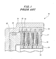
- FIG. 1 is a cross-sectional view illustrating the fundamental construction of a wet-type multiplate clutch 10 , which serves to transmit power between a clutch casing 21 and a hub 22 .
- FIG. 1 shows a spline groove 23 maintained in fitting engagement with separator plates 30 , a spline groove 24 maintained in fitting engagement with friction plates 40 , a piston 25 for pressing the separator plates 30 and friction plates 40 , a backing plate 26 against which the plates 30 , 40 , a snap ring 27 supporting the backing plate 26 , and a sealing ring 28 for the piston 25 .
- the friction plates 40 and separator plates 30 are alternately arranged between the clutch casing 21 and the hub 22 . Engagement or disengagement of the clutch 10 is effected by pressing the friction plates 40 and separator plates 30 with the piston 25 or by canceling the pressing of these plates 40 , 30 .
- friction plates provided with friction linings, each of which has one or more oil grooves having closed ends to separate the friction plates from their associated separator plates during non-engagement of a clutch and also has one or more oil passages extending radially through the friction lining to feed lube oil onto a friction surface for the prevention of seizure during engagement of the clutch.
- the present invention provides a friction plate for a wet-type multiplate clutch, said friction plate being provided with a core plate and friction linings bonded on opposite sides of the core plate, respectively, each of said friction linings being composed of plural segment pieces each having at least one first oil groove and at least one second oil groove, said first oil groove opening to a radially-inner side of its corresponding segment piece and having a closed end portion located in a radially-intermediate part of the corresponding segment piece, and said second oil groove opening to a radially-outer side of the corresponding segment piece and having a closed end portion located in another radially-intermediate part of the corresponding segment piece, wherein each segment piece is provided with at least one press-formed oil groove as one of the first and second oil grooves and at least one punched-out oil groove as the other one of the first and second oil grooves.
- the present invention has made it possible to reduce a drag torque during idling of a clutch and also to avoid grabbing in an initial stage of engagement of the clutch.
- FIG. 1 is a cross-sectional view illustrating the fundamental construction of a wet-type multiplate clutch.
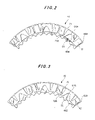
- FIG. 2 is a fragmentary plan view of a friction plate according to a first embodiment of the present invention.
- FIG. 3 is a fragmentary plan view of a friction plate according to a second embodiment of the present invention.
- FIG. 4 is a fragmentary plan view of a friction plate according to a third embodiment of the present invention.
- FIG. 5 is a fragmentary plan view of a friction plate according to a fourth embodiment of the present invention.
- FIG. 6 is a fragmentary plan view of a friction plate according to a fifth embodiment of the present invention.
- FIG. 7 is a fragmentary plan view of a friction plate according to a sixth embodiment of the present invention.
- FIG. 8 is a fragmentary plan view of a friction plate according to a seventh embodiment of the present invention.
- FIG. 9 is a fragmentary plan view of a friction plate according to an eighth embodiment of the present invention.
- FIG. 10 is a fragmentary plan view of a friction plate according to a ninth embodiment of the present invention.
- FIG. 11 is a fragmentary plan view of a friction plate according to a tenth embodiment of the present invention.
- FIG. 12 is a graph illustrating advantageous effects of the present invention.
- the yield of friction linings can be improved by forming each friction lining into segment pieces to be bonded at angular intervals on a core plate.
- An oil groove permits a still smoother flow of lube oil upon drainage when it is formed in such a V-shape that it becomes wider toward its open end.
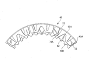
- Friction plates according to various embodiments of the present invention are shown in FIG. 2 through FIG. 11 . All of these figures are common in that plural segment pieces of a friction lining, said plural segment pieces being bonded at angular intervals on each side of a core plate 40 A, are each provided with at least one first oil groove and at least one second oil groove formed therein.
- Reference sign 40 B indicates spline teeth arranged on an inner circumference of the core plate 40 A. It is to be noted that in each embodiment, only one of the segment pieces will be described for the sake of brevity because the segment pieces are identical to each other.
- Each segment piece 51 on a friction plate 41 according to the second embodiment of the present invention as illustrated in FIG. 2 is provided with one press-formed oil groove 61 as a first oil groove and two punched-out oil grooves 71 as second oil grooves.
- These grooves 61 , 71 are each in the form of such a V-shape that it becomes wider toward its open end to facilitate a flow of lube oil.
- oil grooves which are formed in friction linings bonded on friction plates, open to the radially-inner side of the friction linings and have closed ends—can keep uniform the clearances between the friction plates and their associated separator plates during idling owing to the action that separate the friction plates and the separator plates from each other and, when the clutch is disengaged, can smoothly separate the friction plates and the separator plates from each other.
- These oil grooves are, therefore, effective in reducing an idling torque.
- punched-out oil grooves however, the lube oil in the friction lining flows out into the oil grooves through cooling vents in the initial stage of clutch engagement so that the lube oil on the friction surfaces is quickly drained.
- the cushioning effect of the lube oil is, therefore, reduced to cause abrupt grabbing of the clutch in the initial stage of clutch engagement.
- the lube oil in the friction lining is not drained into the press-formed oil groove 61 but is drained onto the friction surface.
- the lube oil therefore, acts as a cushion, thereby avoiding grabbing in the initial stage of clutch engagement.
- FIG. 3 shows some segment pieces 52 on a friction plate 42 according to the second embodiment of the present invention.
- Each segment piece 52 is provided with one punched-out oil groove 62 as a first oil groove and two press-formed oil grooves 72 as second oil grooves.
- FIG. 4 depicts some segment pieces 53 on a friction plate 43 according to the third embodiment of the present invention.
- Each segment piece 53 is provided with a combination of two punched-out oil grooves 63 - 1 and one press-formed oil groove 63 - 2 as first oil grooves and two punched-out oil grooves 73 as second oil grooves.
- FIG. 5 illustrates some segment pieces 54 on a friction plate 44 according to the fourth embodiment of the present invention.
- Each segment piece 54 is provided with two punched-out oil grooves 64 as first oil grooves and a combination of two punched-out oil grooves 74 - 1 and one press-formed oil groove 74 - 2 as second oil grooves.
- FIG. 6 shows some segment pieces 55 on a friction plate 45 according to the fifth embodiment of the present invention.
- Each segment piece 55 is provided with a combination of two punched-out oil grooves 65 - 1 and one press-formed oil groove 65 - 2 as first oil grooves and a combination of one punched-out oil groove 75 - 1 and one press-formed oil groove 75 - 2 as second oil grooves.
- FIG. 7 depicts some segment pieces 56 on a friction plate 46 according to the sixth embodiment of the present invention.
- Each segment piece 56 is provided with a combined punched-out/press-formed oil groove 66 as a first oil groove and two punched-out oil grooves 76 as second oil grooves.
- the combined punched-out/press-formed oil groove 66 is composed of a punched-out groove portion and a press-formed groove portion.
- FIG. 8 illustrates some segment pieces 57 on a friction plate 47 according to the seventh embodiment of the present invention.
- Each segment piece 57 is provided with a punched-out oil groove 67 as a first oil groove and a combination of two combined punched-out/press-formed oil grooves 77 as second oil grooves.
- the combined punched-out/press-formed oil grooves 77 are each composed of a punched-out groove portion and a press-formed groove portion.
- FIG. 9 shows some segment pieces 58 on a friction plate 48 according to the eighth embodiment of the present invention.
- Each segment piece 58 is provided with a combined punched-out/press-formed oil groove 68 as a first oil groove and two combined punched-out/press-formed oil grooves 78 as second oil grooves.
- each combined punched-out/press-formed oil groove is composed of a punched-out groove portion and a press-formed groove portion.
- the oil grooves in the above-described first to eighth embodiments of the present invention are each in the form of such a V-shape that it becomes wider toward its open end.
- two punched-out oil grooves 79 as second oil grooves are similar to the two punched-out oil grooves 71 as the second grooves in the first embodiment, but three press-formed oil grooves 69 as first oil grooves are arranged alternately with the two punched-out oil grooves 79 , are rectangular, and have the same angular width.
- one punched-out oil groove 610 as a first oil groove is similar to the one punched-out oil groove 62 as the second oil groove in the second embodiment, but instead of each of the two press-formed oil grooves 72 as the second oil grooves in the second embodiment, the segment piece 510 is provided with a combination of one press-formed long oil groove 710 - 1 and one press-formed short oil groove 710 - 2 which are the same in angular width but are different in radial length.
- closed end portions 61 A, 62 A, 63 - 1 A, 63 - 2 A, 64 A, 65 - 1 A, 65 - 2 A, 66 A, 67 A, 68 A, 69 A and 610 A of the respective first oil grooves and closed end portions 71 A, 72 A, 73 A, 74 - 1 A, 74 - 2 A, 75 - 1 A, 75 - 2 A, 76 A, 77 A, 78 A, 79 A and 710 - 1 A of the respective second oil grooves are located beyond radial center lines of the corresponding segment pieces, respectively.
- a closed end portion 710 - 2 A of each short oil groove 710 - 2 in FIG. 11 is located short of the radial center line of the corresponding segment piece. Owing to the locations of the respective closed end portions, the respective oil grooves can better exhibit their functions.
- FIG. 12 diagrammatically illustrates advantageous effects of the present invention, in which transmission torque is plotted along the ordinate while time is plotted along the abscissa.
- a broken line B shows time-torque characteristics of a conventional clutch, and the conventional clutch was unable to avoid the occurrence of a large grabbing toque in an initial stage of clutch engagement.
- a solid line A corresponds to the present invention, and indicates the availability of a uniform transmission torque throughout clutch engagement.
Landscapes
- Engineering & Computer Science (AREA)
- General Engineering & Computer Science (AREA)
- Mechanical Engineering (AREA)
- Mechanical Operated Clutches (AREA)
- Hydraulic Clutches, Magnetic Clutches, Fluid Clutches, And Fluid Joints (AREA)
Abstract
Description
- This application claims the priority of Japanese Patent Application 2006-350924 filed Dec. 27, 2006, which is incorporated herein by reference.
- This invention relates to a friction plate for a wet-type multiplate clutch useful as a clutch, a brake or the like in an automatic transmission.
-
FIG. 1 is a cross-sectional view illustrating the fundamental construction of a wet-type multiplate clutch 10, which serves to transmit power between aclutch casing 21 and ahub 22.FIG. 1 shows aspline groove 23 maintained in fitting engagement withseparator plates 30, aspline groove 24 maintained in fitting engagement withfriction plates 40, apiston 25 for pressing theseparator plates 30 andfriction plates 40, abacking plate 26 against which theplates snap ring 27 supporting thebacking plate 26, and asealing ring 28 for thepiston 25. - In the wet-
type multiplate clutch 10, thefriction plates 40 andseparator plates 30 are alternately arranged between theclutch casing 21 and thehub 22. Engagement or disengagement of theclutch 10 is effected by pressing thefriction plates 40 andseparator plates 30 with thepiston 25 or by canceling the pressing of theseplates - Recently, there is an ever-increasing demand for improvements in the fuel economy of automobiles. Keeping in step with this trend, there is an outstanding demand for a further reduction in the idling drag between friction plates and separator plates during non-engagement of a clutch in an automatic transmission.
- There have hence been contemplated friction plates provided with friction linings, each of which has one or more oil grooves having closed ends to separate the friction plates from their associated separator plates during non-engagement of a clutch and also has one or more oil passages extending radially through the friction lining to feed lube oil onto a friction surface for the prevention of seizure during engagement of the clutch. (see, for example, JP-A-11-141570 and JP-A-2005-76759)
- To improve the shift response in an attempt to make not only an improvement in fuel economy and but also improvements in engine performance, the clearances between friction plates and their associated separator plates have become smaller in recent years than before, tending to result in a greater drag torque due to intervening oil films during idling.
- With such conventional friction plates, no sufficient drainage of lube oil is feasible on their friction surfaces, thereby failing to satisfactorily meet the demand for a further reduction in drag torque. Especially during rotation in a low-speed range, the drainage of intervening lube oil between the friction plates and the associated separator plates is not sufficient so that the drag torque cannot be reduced.
- To solve the above-described problem, the present invention provides a friction plate for a wet-type multiplate clutch, said friction plate being provided with a core plate and friction linings bonded on opposite sides of the core plate, respectively, each of said friction linings being composed of plural segment pieces each having at least one first oil groove and at least one second oil groove, said first oil groove opening to a radially-inner side of its corresponding segment piece and having a closed end portion located in a radially-intermediate part of the corresponding segment piece, and said second oil groove opening to a radially-outer side of the corresponding segment piece and having a closed end portion located in another radially-intermediate part of the corresponding segment piece, wherein each segment piece is provided with at least one press-formed oil groove as one of the first and second oil grooves and at least one punched-out oil groove as the other one of the first and second oil grooves.
- Owing to the above-described construction, the present invention has made it possible to reduce a drag torque during idling of a clutch and also to avoid grabbing in an initial stage of engagement of the clutch.
-
FIG. 1 is a cross-sectional view illustrating the fundamental construction of a wet-type multiplate clutch. -
FIG. 2 is a fragmentary plan view of a friction plate according to a first embodiment of the present invention. -
FIG. 3 is a fragmentary plan view of a friction plate according to a second embodiment of the present invention. -
FIG. 4 is a fragmentary plan view of a friction plate according to a third embodiment of the present invention. -
FIG. 5 is a fragmentary plan view of a friction plate according to a fourth embodiment of the present invention. -
FIG. 6 is a fragmentary plan view of a friction plate according to a fifth embodiment of the present invention. -
FIG. 7 is a fragmentary plan view of a friction plate according to a sixth embodiment of the present invention. -
FIG. 8 is a fragmentary plan view of a friction plate according to a seventh embodiment of the present invention. -
FIG. 9 is a fragmentary plan view of a friction plate according to an eighth embodiment of the present invention. -
FIG. 10 is a fragmentary plan view of a friction plate according to a ninth embodiment of the present invention. -
FIG. 11 is a fragmentary plan view of a friction plate according to a tenth embodiment of the present invention. -
FIG. 12 is a graph illustrating advantageous effects of the present invention. - The yield of friction linings can be improved by forming each friction lining into segment pieces to be bonded at angular intervals on a core plate.
- An oil groove permits a still smoother flow of lube oil upon drainage when it is formed in such a V-shape that it becomes wider toward its open end.
- Further, the combined use of at least one punched-out oil groove and at least one press-formed oil groove as the first and second oil grooves has made it possible to provide the friction plate with desired performance.
- Friction plates according to various embodiments of the present invention are shown in
FIG. 2 throughFIG. 11 . All of these figures are common in that plural segment pieces of a friction lining, said plural segment pieces being bonded at angular intervals on each side of acore plate 40A, are each provided with at least one first oil groove and at least one second oil groove formed therein.Reference sign 40B indicates spline teeth arranged on an inner circumference of thecore plate 40A. It is to be noted that in each embodiment, only one of the segment pieces will be described for the sake of brevity because the segment pieces are identical to each other. - Each
segment piece 51 on afriction plate 41 according to the second embodiment of the present invention as illustrated inFIG. 2 is provided with one press-formedoil groove 61 as a first oil groove and two punched-outoil grooves 71 as second oil grooves. Thesegrooves - Because the lube oil is drained to the outside through the punched-out
oil grooves 71 opening to the radially-outer side, it is possible to reduce a drag torque upon idling. Frictional heat is also removed together with the lube oil, so that the heat resistance of the friction lining is improved. - In general, oil grooves which are formed in friction linings bonded on friction plates, open to the radially-inner side of the friction linings and have closed ends—can keep uniform the clearances between the friction plates and their associated separator plates during idling owing to the action that separate the friction plates and the separator plates from each other and, when the clutch is disengaged, can smoothly separate the friction plates and the separator plates from each other. These oil grooves are, therefore, effective in reducing an idling torque. In the case of punched-out oil grooves, however, the lube oil in the friction lining flows out into the oil grooves through cooling vents in the initial stage of clutch engagement so that the lube oil on the friction surfaces is quickly drained. The cushioning effect of the lube oil is, therefore, reduced to cause abrupt grabbing of the clutch in the initial stage of clutch engagement. Owing to the arrangement of the press-formed
oil groove 61 as the first oil groove in the first embodiment to avoid such abrupt grabbing, the cooling vents in the side walls of the oil groove have been caused to collapse. In the initial stage of clutch engagement, the lube oil in the friction lining is not drained into the press-formedoil groove 61 but is drained onto the friction surface. The lube oil, therefore, acts as a cushion, thereby avoiding grabbing in the initial stage of clutch engagement. -
FIG. 3 shows somesegment pieces 52 on afriction plate 42 according to the second embodiment of the present invention. Eachsegment piece 52 is provided with one punched-outoil groove 62 as a first oil groove and two press-formedoil grooves 72 as second oil grooves. -
FIG. 4 depicts somesegment pieces 53 on afriction plate 43 according to the third embodiment of the present invention. Eachsegment piece 53 is provided with a combination of two punched-out oil grooves 63-1 and one press-formed oil groove 63-2 as first oil grooves and two punched-outoil grooves 73 as second oil grooves. -
FIG. 5 illustrates somesegment pieces 54 on afriction plate 44 according to the fourth embodiment of the present invention. Eachsegment piece 54 is provided with two punched-outoil grooves 64 as first oil grooves and a combination of two punched-out oil grooves 74-1 and one press-formed oil groove 74-2 as second oil grooves. -
FIG. 6 shows somesegment pieces 55 on afriction plate 45 according to the fifth embodiment of the present invention. Eachsegment piece 55 is provided with a combination of two punched-out oil grooves 65-1 and one press-formed oil groove 65-2 as first oil grooves and a combination of one punched-out oil groove 75-1 and one press-formed oil groove 75-2 as second oil grooves. -
FIG. 7 depicts somesegment pieces 56 on afriction plate 46 according to the sixth embodiment of the present invention. Eachsegment piece 56 is provided with a combined punched-out/press-formedoil groove 66 as a first oil groove and two punched-outoil grooves 76 as second oil grooves. As illustrated in the figure, the combined punched-out/press-formedoil groove 66 is composed of a punched-out groove portion and a press-formed groove portion. -
FIG. 8 illustrates somesegment pieces 57 on afriction plate 47 according to the seventh embodiment of the present invention. Eachsegment piece 57 is provided with a punched-outoil groove 67 as a first oil groove and a combination of two combined punched-out/press-formedoil grooves 77 as second oil grooves. As illustrated in the figure, the combined punched-out/press-formedoil grooves 77 are each composed of a punched-out groove portion and a press-formed groove portion. -
FIG. 9 shows somesegment pieces 58 on afriction plate 48 according to the eighth embodiment of the present invention. Eachsegment piece 58 is provided with a combined punched-out/press-formedoil groove 68 as a first oil groove and two combined punched-out/press-formedoil grooves 78 as second oil grooves. As illustrated in the figure, each combined punched-out/press-formed oil groove is composed of a punched-out groove portion and a press-formed groove portion. - The oil grooves in the above-described first to eighth embodiments of the present invention are each in the form of such a V-shape that it becomes wider toward its open end. In each of
segment pieces 59 on afriction plate 49 according to the ninth embodiment shown inFIG. 10 , on the other hand, two punched-outoil grooves 79 as second oil grooves are similar to the two punched-outoil grooves 71 as the second grooves in the first embodiment, but three press-formedoil grooves 69 as first oil grooves are arranged alternately with the two punched-outoil grooves 79, are rectangular, and have the same angular width. Further, in each ofsegment pieces 510 on afriction plate 410 according to the tenth embodiment depicted inFIG. 11 , one punched-outoil groove 610 as a first oil groove is similar to the one punched-outoil groove 62 as the second oil groove in the second embodiment, but instead of each of the two press-formedoil grooves 72 as the second oil grooves in the second embodiment, thesegment piece 510 is provided with a combination of one press-formed long oil groove 710-1 and one press-formed short oil groove 710-2 which are the same in angular width but are different in radial length. - In
FIG. 2 throughFIG. 11 ,closed end portions closed end portions FIG. 11 is located short of the radial center line of the corresponding segment piece. Owing to the locations of the respective closed end portions, the respective oil grooves can better exhibit their functions. -
FIG. 12 diagrammatically illustrates advantageous effects of the present invention, in which transmission torque is plotted along the ordinate while time is plotted along the abscissa. - A broken line B shows time-torque characteristics of a conventional clutch, and the conventional clutch was unable to avoid the occurrence of a large grabbing toque in an initial stage of clutch engagement. A solid line A corresponds to the present invention, and indicates the availability of a uniform transmission torque throughout clutch engagement.
Claims (9)
Applications Claiming Priority (2)
| Application Number | Priority Date | Filing Date | Title |
|---|---|---|---|
| JP2006350924A JP2008163960A (en) | 2006-12-27 | 2006-12-27 | Friction plate for wet multi-disc clutch |
| JP2006-350924 | 2006-12-27 |
Publications (2)
| Publication Number | Publication Date |
|---|---|
| US20080156611A1 true US20080156611A1 (en) | 2008-07-03 |
| US8162123B2 US8162123B2 (en) | 2012-04-24 |
Family
ID=39582316
Family Applications (1)
| Application Number | Title | Priority Date | Filing Date |
|---|---|---|---|
| US11/964,201 Active 2029-10-25 US8162123B2 (en) | 2006-12-27 | 2007-12-26 | Friction plate for wet-type multiplate clutch |
Country Status (2)
| Country | Link |
|---|---|
| US (1) | US8162123B2 (en) |
| JP (1) | JP2008163960A (en) |
Cited By (7)
| Publication number | Priority date | Publication date | Assignee | Title |
|---|---|---|---|---|
| US20070102258A1 (en) * | 2005-11-08 | 2007-05-10 | Nsk-Warner K.K. | Friction plate and wet-type multi-plate clutch |
| US20070199794A1 (en) * | 2005-12-20 | 2007-08-30 | Tomoyuki Miyazaki | Friction plate and wet-type multi-plate clutch having such friction plate |
| US20080173516A1 (en) * | 2007-01-16 | 2008-07-24 | Nsk-Warner Kabushiki Kaisha | Friction plate for wet multi-plate clutch |
| US20080179161A1 (en) * | 2007-01-25 | 2008-07-31 | Nsk-Warner K.K. | Friction Plate for Wet-Type Multiplate Clutch |
| US20080223687A1 (en) * | 2007-03-15 | 2008-09-18 | Hideaki Suzuki | Friction Plate for Wet-Type Multiplate Clutch |
| JP2017026158A (en) * | 2016-11-11 | 2017-02-02 | アイシン化工株式会社 | Wet friction material |
| EP3179124A1 (en) * | 2015-12-11 | 2017-06-14 | Miba Frictec GmbH | Friction disc |
Families Citing this family (4)
| Publication number | Priority date | Publication date | Assignee | Title |
|---|---|---|---|---|
| KR101462245B1 (en) * | 2007-08-15 | 2014-11-17 | 보르그워너 인코퍼레이티드 | Frictional part with a zig-zag or undulating circumferential groove in the frictional surface |
| JP2010048272A (en) * | 2008-08-19 | 2010-03-04 | Nsk Warner Kk | Wet type multi-plate clutch |
| JP5965931B2 (en) * | 2013-02-05 | 2016-08-10 | Nskワーナー株式会社 | Wet multi-plate clutch provided with friction plate and friction plate |
| US10850352B2 (en) | 2017-12-21 | 2020-12-01 | GM Global Technology Operations LLC | Method of laser cutting grooves in a friction clutch plate |
Citations (12)
| Publication number | Priority date | Publication date | Assignee | Title |
|---|---|---|---|---|
| US2690248A (en) * | 1950-10-04 | 1954-09-28 | Gen Motors Corp | Clutch plate with grooves for lubricant or coolant |
| US3048250A (en) * | 1959-10-26 | 1962-08-07 | Lambert & Brake Corp | Friction disc for brakes, clutches and the like |
| US4674616A (en) * | 1983-01-31 | 1987-06-23 | Borg-Warner Corporation | Friction disc with segmented core plate and facings |
| US5776288A (en) * | 1996-05-07 | 1998-07-07 | Automotive Composites Company | Method and apparatus for lined clutch plate |
| US6062367A (en) * | 1997-11-11 | 2000-05-16 | Nsk-Warner Kabushiki Kaisha | Friction plate |
| US6145645A (en) * | 1998-07-04 | 2000-11-14 | Borg-Warner Automotive, Gmbh | Disk assembly |
| US20070017773A1 (en) * | 2005-07-20 | 2007-01-25 | Nsk-Warner K.K. | Friction plate for wet-type multi-plate clutch |
| US7172062B2 (en) * | 2003-09-01 | 2007-02-06 | Nsk-Warner Kabushiki Kaisha | Friction plate for wet type multiplate clutch |
| US20070102258A1 (en) * | 2005-11-08 | 2007-05-10 | Nsk-Warner K.K. | Friction plate and wet-type multi-plate clutch |
| US20070199794A1 (en) * | 2005-12-20 | 2007-08-30 | Tomoyuki Miyazaki | Friction plate and wet-type multi-plate clutch having such friction plate |
| US20080173516A1 (en) * | 2007-01-16 | 2008-07-24 | Nsk-Warner Kabushiki Kaisha | Friction plate for wet multi-plate clutch |
| US20080302625A1 (en) * | 2007-06-08 | 2008-12-11 | Nsk-Warner K.K. | Wet type friction plate |
-
2006
- 2006-12-27 JP JP2006350924A patent/JP2008163960A/en active Pending
-
2007
- 2007-12-26 US US11/964,201 patent/US8162123B2/en active Active
Patent Citations (13)
| Publication number | Priority date | Publication date | Assignee | Title |
|---|---|---|---|---|
| US2690248A (en) * | 1950-10-04 | 1954-09-28 | Gen Motors Corp | Clutch plate with grooves for lubricant or coolant |
| US3048250A (en) * | 1959-10-26 | 1962-08-07 | Lambert & Brake Corp | Friction disc for brakes, clutches and the like |
| US4674616A (en) * | 1983-01-31 | 1987-06-23 | Borg-Warner Corporation | Friction disc with segmented core plate and facings |
| US5776288A (en) * | 1996-05-07 | 1998-07-07 | Automotive Composites Company | Method and apparatus for lined clutch plate |
| US6062367A (en) * | 1997-11-11 | 2000-05-16 | Nsk-Warner Kabushiki Kaisha | Friction plate |
| US6145645A (en) * | 1998-07-04 | 2000-11-14 | Borg-Warner Automotive, Gmbh | Disk assembly |
| US7172062B2 (en) * | 2003-09-01 | 2007-02-06 | Nsk-Warner Kabushiki Kaisha | Friction plate for wet type multiplate clutch |
| US20070017773A1 (en) * | 2005-07-20 | 2007-01-25 | Nsk-Warner K.K. | Friction plate for wet-type multi-plate clutch |
| US20070102258A1 (en) * | 2005-11-08 | 2007-05-10 | Nsk-Warner K.K. | Friction plate and wet-type multi-plate clutch |
| US7789209B2 (en) * | 2005-11-08 | 2010-09-07 | Nsk Warner K.K. | Friction plate and wet-type multi-plate clutch |
| US20070199794A1 (en) * | 2005-12-20 | 2007-08-30 | Tomoyuki Miyazaki | Friction plate and wet-type multi-plate clutch having such friction plate |
| US20080173516A1 (en) * | 2007-01-16 | 2008-07-24 | Nsk-Warner Kabushiki Kaisha | Friction plate for wet multi-plate clutch |
| US20080302625A1 (en) * | 2007-06-08 | 2008-12-11 | Nsk-Warner K.K. | Wet type friction plate |
Cited By (15)
| Publication number | Priority date | Publication date | Assignee | Title |
|---|---|---|---|---|
| US20070102258A1 (en) * | 2005-11-08 | 2007-05-10 | Nsk-Warner K.K. | Friction plate and wet-type multi-plate clutch |
| US7789209B2 (en) * | 2005-11-08 | 2010-09-07 | Nsk Warner K.K. | Friction plate and wet-type multi-plate clutch |
| US8146725B2 (en) | 2005-12-20 | 2012-04-03 | Nsk-Warner K.K. | Friction plate and wet-type multi-plate clutch having such friction plate |
| US20070199794A1 (en) * | 2005-12-20 | 2007-08-30 | Tomoyuki Miyazaki | Friction plate and wet-type multi-plate clutch having such friction plate |
| US8714333B2 (en) | 2005-12-20 | 2014-05-06 | Nsk-Warner K.K. | Friction plate and wet-type multi-plate clutch having such friction plate |
| US8327992B2 (en) | 2005-12-20 | 2012-12-11 | Nsk-Warner K.K. | Friction plate and wet-type multi-plate clutch having such friction plate |
| US20080173516A1 (en) * | 2007-01-16 | 2008-07-24 | Nsk-Warner Kabushiki Kaisha | Friction plate for wet multi-plate clutch |
| US7984801B2 (en) * | 2007-01-16 | 2011-07-26 | Nsk-Warner Kabushiki Kaisha | Friction plate for wet multi-plate clutch |
| US20080179161A1 (en) * | 2007-01-25 | 2008-07-31 | Nsk-Warner K.K. | Friction Plate for Wet-Type Multiplate Clutch |
| US7980375B2 (en) * | 2007-03-15 | 2011-07-19 | Nsk-Warner K.K. | Friction plate for wet-type multiplate clutch |
| US20080223687A1 (en) * | 2007-03-15 | 2008-09-18 | Hideaki Suzuki | Friction Plate for Wet-Type Multiplate Clutch |
| EP3179124A1 (en) * | 2015-12-11 | 2017-06-14 | Miba Frictec GmbH | Friction disc |
| AT518017A1 (en) * | 2015-12-11 | 2017-06-15 | Miba Frictec Gmbh | friction plate |
| AT518017B1 (en) * | 2015-12-11 | 2017-12-15 | Miba Frictec Gmbh | friction plate |
| JP2017026158A (en) * | 2016-11-11 | 2017-02-02 | アイシン化工株式会社 | Wet friction material |
Also Published As
| Publication number | Publication date |
|---|---|
| US8162123B2 (en) | 2012-04-24 |
| JP2008163960A (en) | 2008-07-17 |
Similar Documents
| Publication | Publication Date | Title |
|---|---|---|
| US8162123B2 (en) | Friction plate for wet-type multiplate clutch | |
| US7958984B2 (en) | Friction plate for wet-type multiplate clutch | |
| US8327992B2 (en) | Friction plate and wet-type multi-plate clutch having such friction plate | |
| US7789209B2 (en) | Friction plate and wet-type multi-plate clutch | |
| US20080179161A1 (en) | Friction Plate for Wet-Type Multiplate Clutch | |
| US7984801B2 (en) | Friction plate for wet multi-plate clutch | |
| US7527135B2 (en) | Multiplate friction clutch | |
| CN105299079A (en) | Friction plates and wet multi-plate clutches with friction plates | |
| US20080302625A1 (en) | Wet type friction plate | |
| US20070151822A1 (en) | Wet-type multi-plate clutch | |
| US7980375B2 (en) | Friction plate for wet-type multiplate clutch | |
| US20080236985A1 (en) | Wet type friction plate | |
| US7597180B2 (en) | Friction plate for wet-type multiplate clutch | |
| US7823714B2 (en) | Friction plate for wet-type multiplate clutch | |
| US20070251795A1 (en) | Wet-type multi-plate clutch | |
| US20080223686A1 (en) | Wet type friction plate | |
| JP2009138901A (en) | Torque transmitting mechanism for automatic transmission | |
| JP6782740B2 (en) | Wet multi-plate clutch with friction plate and friction plate | |
| JP4385056B2 (en) | Wet multi-plate clutch friction plate | |
| JP4574632B2 (en) | Wet multi-plate clutch friction plate | |
| JP2026002240A (en) | Friction plate and wet multi-plate clutch equipped with friction plate | |
| JP2005351325A (en) | Wet multi-plate clutch | |
| JP2009138902A (en) | Torque transmitting mechanism for automatic transmission |
Legal Events
| Date | Code | Title | Description |
|---|---|---|---|
| AS | Assignment |
Owner name: NSK-WARNER K.K., JAPAN Free format text: ASSIGNMENT OF ASSIGNORS INTEREST;ASSIGNOR:HIRAYANAGI, TSUYOSHI;REEL/FRAME:027887/0389 Effective date: 20071210 |
|
| STCF | Information on status: patent grant |
Free format text: PATENTED CASE |
|
| FEPP | Fee payment procedure |
Free format text: PAYOR NUMBER ASSIGNED (ORIGINAL EVENT CODE: ASPN); ENTITY STATUS OF PATENT OWNER: LARGE ENTITY |
|
| FPAY | Fee payment |
Year of fee payment: 4 |
|
| MAFP | Maintenance fee payment |
Free format text: PAYMENT OF MAINTENANCE FEE, 8TH YEAR, LARGE ENTITY (ORIGINAL EVENT CODE: M1552); ENTITY STATUS OF PATENT OWNER: LARGE ENTITY Year of fee payment: 8 |
|
| MAFP | Maintenance fee payment |
Free format text: PAYMENT OF MAINTENANCE FEE, 12TH YEAR, LARGE ENTITY (ORIGINAL EVENT CODE: M1553); ENTITY STATUS OF PATENT OWNER: LARGE ENTITY Year of fee payment: 12 |