US20080044136A1 - Retention release auxiliary device for optical connector and printed circuit board device - Google Patents
Retention release auxiliary device for optical connector and printed circuit board device Download PDFInfo
- Publication number
- US20080044136A1 US20080044136A1 US11/889,656 US88965607A US2008044136A1 US 20080044136 A1 US20080044136 A1 US 20080044136A1 US 88965607 A US88965607 A US 88965607A US 2008044136 A1 US2008044136 A1 US 2008044136A1
- Authority
- US
- United States
- Prior art keywords
- lever
- plug
- optical connector
- receptacle
- operating
- Prior art date
- Legal status (The legal status is an assumption and is not a legal conclusion. Google has not performed a legal analysis and makes no representation as to the accuracy of the status listed.)
- Granted
Links
Images




Classifications
-
- G—PHYSICS
- G02—OPTICS
- G02B—OPTICAL ELEMENTS, SYSTEMS OR APPARATUS
- G02B6/00—Light guides; Structural details of arrangements comprising light guides and other optical elements, e.g. couplings
- G02B6/24—Coupling light guides
- G02B6/36—Mechanical coupling means
- G02B6/38—Mechanical coupling means having fibre to fibre mating means
- G02B6/3807—Dismountable connectors, i.e. comprising plugs
- G02B6/389—Dismountable connectors, i.e. comprising plugs characterised by the method of fastening connecting plugs and sockets, e.g. screw- or nut-lock, snap-in, bayonet type
- G02B6/3893—Push-pull type, e.g. snap-in, push-on
Definitions
- the present invention relates to a retention release auxiliary device for an optical connector including a plug to which optical fibers are coupled and a receptacle into which the plug is inserted.
- optical fiber communication has become mainstream. Further, it is required to increase the number of optical lines and the density thereof.
- a communication device is installed in each node of an optical communication system.
- a printed circuit board having a function of housing an optical line and controlling the same is mounted on a rack shelf of the communication device.
- An interface optical connector is mounted on the printed circuit board and optical fibers are detachably connected to the optical connector.
- Such optical connectors having various shapes are proposed or standardized (see Japanese unexamined patent publication Nos. 2005-17602 and 11-64682 and Japanese patent No. 3390697).
- an LC type connector that can be decreased in size and increased in density is normally used in a communication carrier in North America.
- Such an optical connector has a latch mechanism for retention.
- a plug to which optical fibers are connected is inserted into a receptacle and thereby the latch mechanism operates automatically, ensuring the coupling between the plug and the receptacle.
- the plug can be detached from the receptacle.
- a plurality of the printed circuit boards described above are densely mounted on a shelf.
- a receptacle of an optical connector is attached to a step-like front plate that is fastened to each of the printed circuit boards.
- an object of an embodiment of the present invention is to improve operability for retention release of an optical connector used for connection of optical fibers.
- Another object of an embodiment of the present invention is to facilitate attachment/detachment of a plug even in the case where an optical connector is provided in a small space.
- a device is a retention release auxiliary device for an optical connector, the optical connector including a plug to which optical fibers are coupled and a receptacle into which the plug is inserted.
- the plug is provided with a lever on a front side of a body of the plug, the lever being elastically deformable to approach the body of the plug by operating an end portion of the lever with fingers.
- An engaging portion formed in the lever engages with an engaging portion provided in the receptacle, leading to retention of the engaging portion of the lever and the engaging portion of the receptacle.
- the retention release auxiliary device includes a base member that is fixedly provided with respect to the receptacle, and an auxiliary lever that is provided in an elastically deformable manner with respect to the base member.
- the auxiliary lever includes a base part extending to the base member, a pressing part that extends to the base part and is touchable to the end portion of the lever, and an operating part that extends to the pressing part and is disposed at a position closer to the body of the plug than the end portion of the lever is. The pressing part presses against the end portion of the lever, moves the lever by operating the operating part with fingers, enabling release of the engagement between the engaging portions.
- the operating part may be disposed on a side surface side of the body of the plug and may be operable with fingers on the side surface side of the body of the plug.
- the operating part may have a plane-like shape extending along an axis direction of the plug, and the operating part and the pressing part may be connected to each other via a plane and may form a substantially Z-shape as viewed from a lateral side.
- the receptacle may be configured to receive at least two plugs side by side therein, and the base member may be provided with two of the auxiliary levers, and the operating parts of the two auxiliary levers may be disposed on side surface sides opposite to the bodies of the plugs respectively, enabling separate operation of the two plugs.
- a printed circuit board device includes an optical connector that is mounted on a front side of a printed circuit boar, and the retention release auxiliary device for an optical connector described above that is attached to the optical connector.
- the structure described above can improve operability for retention release of an optical connector used for connection of optical fibers.
- the structure described above can facilitate attachment/detachment of a plug even in the case where an optical connector is provided in a small space.
- FIG. 1 is a front view of a printed circuit board on which an optical connector according to the present invention is mounted.
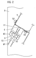
- FIG. 2 is a right side view of a printed circuit board.
- FIG. 3 is a perspective view of the optical connector shown in FIG. 2 .
- FIG. 5A is a top view of a plug constituting an optical connector and FIG. 5B is a front view of the same.
- FIG. 6 is a right side view of an optical connector.
- FIG. 7 is a top sectional view of an optical connector.
- FIG. 8 is a front view of a release auxiliary device.
- FIG. 9 is a plan view of a release auxiliary device.
- FIG. 10 is a right side view of a release auxiliary device.
- FIG. 11 is a cross sectional view showing the main part of an optical connector to which a release auxiliary device is attached.
- FIG. 1 is a front view of a printed circuit board 3 on which an optical connector 5 according to the present invention is mounted
- FIG. 2 is a right side view of the printed circuit board 3
- FIG. 3 is a perspective view when the optical connector 5 shown in FIG. 2 is viewed from the lower right on the front surface side of the printed circuit board 3 shown in FIG. 2
- FIG. 4 is a perspective view when the optical connector 5 shown in FIG. 2 is viewed from the lower right on the rear surface side of the printed circuit board 3 shown in FIG. 2
- FIG. 5A is a top view of a plug 12 constituting the optical connector 5
- FIG. 5B is a front view of the same
- FIG. 6 is a right side view of the optical connector 5
- FIG. 1 is a front view of a printed circuit board 3 on which an optical connector 5 according to the present invention is mounted
- FIG. 2 is a right side view of the printed circuit board 3
- FIG. 3 is a perspective view when the optical connector 5 shown in FIG. 2 is viewed from
- FIG. 7 is a top sectional view of the optical connector 5
- FIG. 8 is a front view of a release auxiliary device 6
- FIG. 9 is a plan view of the release auxiliary device 6
- FIG. 10 is a right side view of the release auxiliary device 6
- FIG. 11 is a cross sectional view showing the main part of the optical connector 5 to which the release auxiliary device 6 is attached.
- a plurality of printed circuit boards 3 , 3 b and 3 c are mounted within a rack shelf of a communication device.
- the printed circuit boards 3 , 3 b and 3 c are densely disposed in parallel to one another.
- a front plate 7 that is made of a thin metal plate and formed in a step-like shape is attached to the printed circuit board 3 .
- the optical connector 5 and the release auxiliary device 6 are attached to the front plate 7 .
- the optical connector 5 shown in this embodiment is a duplex optical connector in which two receptacles are formed to be integral with each other and a plug coupled to optical fibers is inserted into each of the receptacles. Since the receptacles have the same structure and the plugs have the same structure, a description is given here of one of the receptacles and one of the plugs.
- the optical connector 5 includes the plug 12 to which the optical fibers HF are coupled and the receptacle 11 into which the plug 12 is inserted.
- the optical connector 5 itself is a well-known LC type optical connector. Accordingly, since the shape, the structure, the operation method of each of the receptacle 11 and the plug 12 themselves are known, only a brief description is given here.
- the plug 12 of the optical connector 5 is inserted into the receptacle 11 from the lower left toward the upper right on the front surface side in FIG. 2 and is connected to the receptacle 11 , and thereby the optical connector 5 is attached in a manner to project from the front plate 7 .
- the plug 12 should be pulled downward in FIG. 2 while operating the release auxiliary device 6 with fingers.
- the receptacle 11 includes a housing 21 that is made of synthetic resin and has a rectangular parallelepiped shape, a split sleeve 22 that is made of zirconia or the like and provided in the middle of the inside of the receptacle 11 and a plate 23 that is made of a spring material.
- the housing 21 is provided with two holes 25 .
- the plugs 12 are inserted from openings provided on both sides of the respective holes 25 .
- An LC ferrule 43 that is provided in an end portion of each of the two plugs 12 inserted from the both sides into the same hole 25 touches to (abuts against) an end surface of the split sleeve 22 and is optically coupled to the optical fibers HF.
- the housing 21 has an inner surface that has a shape adapted to hold the plug 12 when the plug 12 is inserted.
- the hole 25 of the housing 21 has a shape substantially the same as the cross-sectional shape of a body 40 of the plug 12 .
- projections 28 are formed which have a function of engaging with engaging convex portions 42 provided on both sides of a lever 41 of the plug 12 and of retaining the engaging convex portions 42 (see FIG. 11 ).
- the body 40 of the plug 12 is made of synthetic resin and is like a prism having a substantially square cross section.
- the lever 41 described above is formed to be integral with the body 40 on a side surface thereof on the front side.
- the lever 41 has elasticity and is capable of being deformed elastically to be close to the body 40 of the plug 12 by operating the end portion of the lever 41 with fingers.
- the engaging convex portions 42 are provided on both end surfaces in almost the center of the lever 41 to project from the lever 41 on both sides as shown in FIG. 5A .
- An end portion of the body 40 is provided with the LC ferrule 43 that is made of zirconia or the like and has a cylinder-like shape.
- the LC ferrule 43 is optically coupled, inside the body 40 , to the optical fibers HF inserted from the rear end of the body 40 .
- the rear end portion of the body 40 is covered with a tube 44 that serves to protect an extending part of the optical fibers HF.
- the plug 12 in order to insert the plug 12 into the receptacle 11 , the plug 12 is inserted into the hole 25 of the receptacle 11 as it is. Thereby, the lever 41 is pushed by the wall surface of the receptacle 11 and deforms elastically, and the engaging convex portions 42 engage with the projections 28 , so that the plug 12 is retained. In order to detach the plug 12 from the receptacle 11 , the lever 41 is caused to be deformed against the elastic force thereof by holding the end of the lever 41 with fingers. Thereby, the engagement between the engaging convex portions 42 and the projections 28 is released, and under this condition the plug 12 is detached from the receptacle 11 .
- the release auxiliary device 6 includes a base member 51 and an auxiliary lever 52 that are made of synthetic resin and are formed to be integral with each other.
- the base member 51 is fixedly provided with respect to the receptacle 11 while the auxiliary lever 52 is provided in an elastically deformable manner with respect to the base member 51 .
- the auxiliary lever 52 includes a base part 61 extending to the base member 51 , a pressing part 62 that extends to the base part 61 and is touchable to the end portion of the lever 41 and an operating part 63 that extends to the pressing part 62 and is disposed at a position closer to the body 40 of the plug 12 than the end portion of the lever 41 is. All of the base part 61 , the pressing part 62 and the operating part 63 are formed to have a thin plate shape.
- the base part 61 and the pressing part 62 have a large width while the operating part 63 has a small width. Such a structure prevents the interference with the plug 12 in the case where the operating part 63 is operated.
- the base part 61 deflects, and at a position P 2 , the pressing part 62 presses against the end portion of the lever 41 and the lever 41 is moved in the direction shown by the arrow. Thereby, the engagement between the engaging convex portions 42 of the lever 41 and the projections 28 of the receptacle 11 is released, so that the plug 12 can be easily detached from the receptacle 11 .
- the pressing part 62 is not in contact with the lever 41 in the free state, and the pressing part 62 comes into contact with the lever 41 when the operating part 63 is operated.
- the operating part 63 has a plane-like shape extending along the axis direction of the plug 12 .
- the operating part 63 and the pressing part 62 are connected to each other via a plane and they form a substantially Z-shape as viewed from the lateral side.
- the pressing part 62 forms a V-shape as viewed from the lateral side.
- the pressing part 62 may have a plane-like shape parallel to the operating part 63 .
- the two plugs 12 can be inserted into the receptacles 11 side by side.
- the base member 51 is provided with the two auxiliary levers 52 , and the operating parts 63 of the two auxiliary levers 52 are arranged on side surfaces opposite to the bodies 40 of the plugs 12 respectively.
- Such a structure enables separate operation of the levers 41 of the two plugs 12 .
- the release auxiliary device 6 may be provided with three or more of the auxiliary levers 52 in accordance with the number of series of the receptacles 11 .
- the release auxiliary device 6 may be provided with, for example, a single lever 41 regardless of the number of series of the receptacles 11 .
- the release auxiliary device 6 may be elastically engaged with the receptacle 11 and be fixed thereto by covering the receptacle 11 with the release auxiliary device 6 , instead of fastening the release auxiliary device 6 to the front plate 7 with a screw.
- An operation example is as follows. Referring to FIG. 1 , for example, fingers are inserted between the printed circuit board 3 c and the operating part 63 , and the operating part 63 is moved, with fingers, to the left in the drawing. This operation releases the engagement of the lever 41 , so that the plug 12 can be easily detached from the receptacle 11 .
- the operating part 63 is disposed on the side surface side of the body 40 of the plug 12 . Accordingly, a space for inserting fingers for operation of the operating part 63 is secured.
- the base member 51 is fastened to the front plate 7 with two screws.
- the base member 51 is fastened to the front plate 7 with a screw at one position and is caused to be engaged with the front plate 7 with a projection or the like at another position.
- the release auxiliary device 6 described above is produced by molding using synthetic resin. However, it may be produced by a different method, e.g., by sheet metal working of a metal sheet.
- the release auxiliary device 6 In the release auxiliary device 6 described above, the overall structure of the base part 61 , the pressing part 62 , the operating part 63 , the auxiliary lever 52 , the base member 51 and the release auxiliary device 6 , the structures of various portions thereof, the shape, the size, the number, and the materials thereof, and the like may be changed as needed, in accordance with the subject matter of the present invention. Further, the release auxiliary device 6 can be applied to optical connectors having various shapes and structures as the optical connector 5 .
Landscapes
- Physics & Mathematics (AREA)
- General Physics & Mathematics (AREA)
- Optics & Photonics (AREA)
- Mechanical Coupling Of Light Guides (AREA)
Abstract
Description
- 1. Field of the Invention
- The present invention relates to a retention release auxiliary device for an optical connector including a plug to which optical fibers are coupled and a receptacle into which the plug is inserted.
- 2. Description of the Related Art
- Along with expansion of information networks in recent years, optical fiber communication has become mainstream. Further, it is required to increase the number of optical lines and the density thereof.
- A communication device is installed in each node of an optical communication system. A printed circuit board having a function of housing an optical line and controlling the same is mounted on a rack shelf of the communication device. An interface optical connector is mounted on the printed circuit board and optical fibers are detachably connected to the optical connector. Such optical connectors having various shapes are proposed or standardized (see Japanese unexamined patent publication Nos. 2005-17602 and 11-64682 and Japanese patent No. 3390697). For example, an LC type connector that can be decreased in size and increased in density is normally used in a communication carrier in North America.
- Such an optical connector has a latch mechanism for retention. A plug to which optical fibers are connected is inserted into a receptacle and thereby the latch mechanism operates automatically, ensuring the coupling between the plug and the receptacle. When a lever provided in the plug is operated by fingers to release the latch mechanism, the plug can be detached from the receptacle.
- Upon the detachment of the plug, in the case of an environment where a sufficient space is secured, it is easy to operate a small lever with fingers and release the latch mechanism. However, it is not easy in the case where an optical connector is mounted in a small space.
- Specifically, usually, a plurality of the printed circuit boards described above are densely mounted on a shelf. In the case where, for example, a plurality of the printed circuit boards are made adjacent to one another and are installed in a slot, a receptacle of an optical connector is attached to a step-like front plate that is fastened to each of the printed circuit boards. In this case, it is necessary to house also an extension area of optical fibers connected to the optical connector in an area within the shelf. Accordingly, it necessarily follows that the mounting position of the optical connector is a position back from the shelf surface. Under this condition, it is difficult to put fingers in order to attach/detach the plug. In particular, it is hard to operate the lever with fingers to release the latch mechanism.
- For this reason, upon the detachment of the plug, a tool is conventionally necessary to release the latch mechanism.
- The present disclosure is directed to solve the problems pointed out above, and therefore, an object of an embodiment of the present invention is to improve operability for retention release of an optical connector used for connection of optical fibers. Another object of an embodiment of the present invention is to facilitate attachment/detachment of a plug even in the case where an optical connector is provided in a small space.
- A device according to one aspect of the present invention is a retention release auxiliary device for an optical connector, the optical connector including a plug to which optical fibers are coupled and a receptacle into which the plug is inserted. The plug is provided with a lever on a front side of a body of the plug, the lever being elastically deformable to approach the body of the plug by operating an end portion of the lever with fingers. An engaging portion formed in the lever engages with an engaging portion provided in the receptacle, leading to retention of the engaging portion of the lever and the engaging portion of the receptacle. The lever is caused to be deformed against an elastic force thereof by operating the end portion of the lever with fingers, so that the engagement between the engaging portions is released, enabling detachment of the plug from the receptacle. The retention release auxiliary device includes a base member that is fixedly provided with respect to the receptacle, and an auxiliary lever that is provided in an elastically deformable manner with respect to the base member. The auxiliary lever includes a base part extending to the base member, a pressing part that extends to the base part and is touchable to the end portion of the lever, and an operating part that extends to the pressing part and is disposed at a position closer to the body of the plug than the end portion of the lever is. The pressing part presses against the end portion of the lever, moves the lever by operating the operating part with fingers, enabling release of the engagement between the engaging portions.
- Preferably, the operating part may be disposed on a side surface side of the body of the plug and may be operable with fingers on the side surface side of the body of the plug.
- Further, the operating part may have a plane-like shape extending along an axis direction of the plug, and the operating part and the pressing part may be connected to each other via a plane and may form a substantially Z-shape as viewed from a lateral side.
- Furthermore, the receptacle may be configured to receive at least two plugs side by side therein, and the base member may be provided with two of the auxiliary levers, and the operating parts of the two auxiliary levers may be disposed on side surface sides opposite to the bodies of the plugs respectively, enabling separate operation of the two plugs.
- According to another aspect of the present invention, a printed circuit board device includes an optical connector that is mounted on a front side of a printed circuit boar, and the retention release auxiliary device for an optical connector described above that is attached to the optical connector.
- The structure described above can improve operability for retention release of an optical connector used for connection of optical fibers. In addition, the structure described above can facilitate attachment/detachment of a plug even in the case where an optical connector is provided in a small space.
- These and other characteristics and objects of the present invention will become more apparent by the following descriptions of preferred embodiments with reference to drawings.
-
FIG. 1 is a front view of a printed circuit board on which an optical connector according to the present invention is mounted. -
FIG. 2 is a right side view of a printed circuit board. -
FIG. 3 is a perspective view of the optical connector shown inFIG. 2 . -
FIG. 4 is a perspective view of the optical connector shown inFIG. 2 . -
FIG. 5A is a top view of a plug constituting an optical connector andFIG. 5B is a front view of the same. -
FIG. 6 is a right side view of an optical connector. -
FIG. 7 is a top sectional view of an optical connector. -
FIG. 8 is a front view of a release auxiliary device. -
FIG. 9 is a plan view of a release auxiliary device. -
FIG. 10 is a right side view of a release auxiliary device. -
FIG. 11 is a cross sectional view showing the main part of an optical connector to which a release auxiliary device is attached. -
FIG. 1 is a front view of a printedcircuit board 3 on which anoptical connector 5 according to the present invention is mounted,FIG. 2 is a right side view of the printedcircuit board 3,FIG. 3 is a perspective view when theoptical connector 5 shown inFIG. 2 is viewed from the lower right on the front surface side of the printedcircuit board 3 shown inFIG. 2 ,FIG. 4 is a perspective view when theoptical connector 5 shown inFIG. 2 is viewed from the lower right on the rear surface side of the printedcircuit board 3 shown inFIG. 2 ,FIG. 5A is a top view of aplug 12 constituting theoptical connector 5 andFIG. 5B is a front view of the same,FIG. 6 is a right side view of theoptical connector 5,FIG. 7 is a top sectional view of theoptical connector 5,FIG. 8 is a front view of a releaseauxiliary device 6,FIG. 9 is a plan view of the releaseauxiliary device 6,FIG. 10 is a right side view of the releaseauxiliary device 6, andFIG. 11 is a cross sectional view showing the main part of theoptical connector 5 to which the releaseauxiliary device 6 is attached. - Referring to
FIGS. 1-4 , a plurality of printedcircuit boards circuit boards front plate 7 that is made of a thin metal plate and formed in a step-like shape is attached to the printedcircuit board 3. Theoptical connector 5 and the releaseauxiliary device 6 are attached to thefront plate 7. - The
optical connector 5 shown in this embodiment is a duplex optical connector in which two receptacles are formed to be integral with each other and a plug coupled to optical fibers is inserted into each of the receptacles. Since the receptacles have the same structure and the plugs have the same structure, a description is given here of one of the receptacles and one of the plugs. - As described above, the
optical connector 5 includes theplug 12 to which the optical fibers HF are coupled and thereceptacle 11 into which theplug 12 is inserted. Theoptical connector 5 itself is a well-known LC type optical connector. Accordingly, since the shape, the structure, the operation method of each of thereceptacle 11 and theplug 12 themselves are known, only a brief description is given here. - As clearly shown in
FIG. 2 , theplug 12 of theoptical connector 5 is inserted into thereceptacle 11 from the lower left toward the upper right on the front surface side inFIG. 2 and is connected to thereceptacle 11, and thereby theoptical connector 5 is attached in a manner to project from thefront plate 7. In order to detach theplug 12 from thereceptacle 11, theplug 12 should be pulled downward inFIG. 2 while operating the releaseauxiliary device 6 with fingers. - Referring further to
FIGS. 6 and 7 , thereceptacle 11 includes ahousing 21 that is made of synthetic resin and has a rectangular parallelepiped shape, asplit sleeve 22 that is made of zirconia or the like and provided in the middle of the inside of thereceptacle 11 and aplate 23 that is made of a spring material. Thehousing 21 is provided with twoholes 25. Theplugs 12 are inserted from openings provided on both sides of the respective holes 25. AnLC ferrule 43 that is provided in an end portion of each of the twoplugs 12 inserted from the both sides into thesame hole 25 touches to (abuts against) an end surface of thesplit sleeve 22 and is optically coupled to the optical fibers HF. - In order to attach the
receptacle 11 to thefront plate 7, a side of thereceptacle 11 in which theplate 23 is provided is inserted from the rear side of thefront plate 7 into a rectangular hole provided on thefront plate 7. An edge of theplate 23 and acollar 26 provided in thehousing 21 sandwich thefront plate 7 at a position where theplate 23 penetrates to the front side of thefront plate 7. Thereby, thereceptacle 11 is fixed to thefront plate 7. A part of the wall surfaces of thehousing 21 is provided withslit windows 27 leading to theholes 25. - The
housing 21 has an inner surface that has a shape adapted to hold theplug 12 when theplug 12 is inserted. For example, thehole 25 of thehousing 21 has a shape substantially the same as the cross-sectional shape of abody 40 of theplug 12. Further,projections 28 are formed which have a function of engaging with engagingconvex portions 42 provided on both sides of alever 41 of theplug 12 and of retaining the engaging convex portions 42 (seeFIG. 11 ). - Referring to
FIGS. 5A and 5B , thebody 40 of theplug 12 is made of synthetic resin and is like a prism having a substantially square cross section. Thelever 41 described above is formed to be integral with thebody 40 on a side surface thereof on the front side. Thelever 41 has elasticity and is capable of being deformed elastically to be close to thebody 40 of theplug 12 by operating the end portion of thelever 41 with fingers. The engagingconvex portions 42 are provided on both end surfaces in almost the center of thelever 41 to project from thelever 41 on both sides as shown inFIG. 5A . An end portion of thebody 40 is provided with theLC ferrule 43 that is made of zirconia or the like and has a cylinder-like shape. TheLC ferrule 43 is optically coupled, inside thebody 40, to the optical fibers HF inserted from the rear end of thebody 40. The rear end portion of thebody 40 is covered with atube 44 that serves to protect an extending part of the optical fibers HF. - Referring to
FIG. 11 again, in order to insert theplug 12 into thereceptacle 11, theplug 12 is inserted into thehole 25 of thereceptacle 11 as it is. Thereby, thelever 41 is pushed by the wall surface of thereceptacle 11 and deforms elastically, and the engagingconvex portions 42 engage with theprojections 28, so that theplug 12 is retained. In order to detach theplug 12 from thereceptacle 11, thelever 41 is caused to be deformed against the elastic force thereof by holding the end of thelever 41 with fingers. Thereby, the engagement between the engagingconvex portions 42 and theprojections 28 is released, and under this condition theplug 12 is detached from thereceptacle 11. - Next, referring to
FIGS. 8-10 , the releaseauxiliary device 6 includes abase member 51 and anauxiliary lever 52 that are made of synthetic resin and are formed to be integral with each other. Thebase member 51 is fixedly provided with respect to thereceptacle 11 while theauxiliary lever 52 is provided in an elastically deformable manner with respect to thebase member 51. - The
base member 51 includes aflat plate part 55 that has a rectangular shape and has a rectangular hole through which thereceptacle 11 passes and avertical plate part 56 that extends from one edge of theflat plate part 55 in the vertical direction. Theflat plate part 55 and the vertical plate part have ahole 58. Ascrew 59 is inserted into thehole 58 and is screwed in a screw hole provided in thefront plate 7, so that the releaseauxiliary device 6 is fastened to thefront plate 7. Thereby, the releaseauxiliary device 6 is fixedly provided with respect to thereceptacle 11. - The
auxiliary lever 52 includes abase part 61 extending to thebase member 51, apressing part 62 that extends to thebase part 61 and is touchable to the end portion of thelever 41 and an operatingpart 63 that extends to thepressing part 62 and is disposed at a position closer to thebody 40 of theplug 12 than the end portion of thelever 41 is. All of thebase part 61, thepressing part 62 and the operatingpart 63 are formed to have a thin plate shape. - More specifically, as clearly shown in
FIG. 9 , thebase part 61 and thepressing part 62 have a large width while the operatingpart 63 has a small width. Such a structure prevents the interference with theplug 12 in the case where the operatingpart 63 is operated. - Referring to
FIG. 11 , at a position P1, when the operatingpart 63 is operated by pressing the same with fingers, thebase part 61 deflects, and at a position P2, thepressing part 62 presses against the end portion of thelever 41 and thelever 41 is moved in the direction shown by the arrow. Thereby, the engagement between the engagingconvex portions 42 of thelever 41 and theprojections 28 of thereceptacle 11 is released, so that theplug 12 can be easily detached from thereceptacle 11. Note that thepressing part 62 is not in contact with thelever 41 in the free state, and thepressing part 62 comes into contact with thelever 41 when the operatingpart 63 is operated. - The following is a further detailed description of the release
auxiliary device 6. - The operating
part 63 is disposed on a side surface side of thebody 40 of theplug 12, i.e., on a side surface side with respect to a surface on which thelever 41 of theplug 12 is provided. This structure enables a user to operate the operatingpart 63 with fingers on the side surface side of thebody 40 of theplug 12. Further, even in the case where theoptical connector 5 is attached in a small space, a space necessary for operating the operatingpart 63 is secured. Furthermore, interference due to the touch of fingers on theplug 12 does not occur and a user can release the engagement of thelever 41 with easy operation. - The operating
part 63 has a plane-like shape extending along the axis direction of theplug 12. The operatingpart 63 and thepressing part 62 are connected to each other via a plane and they form a substantially Z-shape as viewed from the lateral side. In this embodiment, thepressing part 62 forms a V-shape as viewed from the lateral side. Instead, however, thepressing part 62 may have a plane-like shape parallel to the operatingpart 63. - As described earlier, since the
receptacle 11 according to this embodiment is duplex, the twoplugs 12 can be inserted into thereceptacles 11 side by side. As clearly shown inFIG. 9 , in the releaseauxiliary device 6, thebase member 51 is provided with the twoauxiliary levers 52, and the operatingparts 63 of the twoauxiliary levers 52 are arranged on side surfaces opposite to thebodies 40 of theplugs 12 respectively. Such a structure enables separate operation of thelevers 41 of the two plugs 12. - The release
auxiliary device 6 may be provided with three or more of theauxiliary levers 52 in accordance with the number of series of thereceptacles 11. Alternatively, the releaseauxiliary device 6 may be provided with, for example, asingle lever 41 regardless of the number of series of thereceptacles 11. In such a case, the releaseauxiliary device 6 may be elastically engaged with thereceptacle 11 and be fixed thereto by covering thereceptacle 11 with the releaseauxiliary device 6, instead of fastening the releaseauxiliary device 6 to thefront plate 7 with a screw. - An operation example is as follows. Referring to
FIG. 1 , for example, fingers are inserted between the printedcircuit board 3 c and the operatingpart 63, and the operatingpart 63 is moved, with fingers, to the left in the drawing. This operation releases the engagement of thelever 41, so that theplug 12 can be easily detached from thereceptacle 11. The operatingpart 63 is disposed on the side surface side of thebody 40 of theplug 12. Accordingly, a space for inserting fingers for operation of the operatingpart 63 is secured. - In the embodiments described above, the
base member 51 is fastened to thefront plate 7 with two screws. Instead, however, another structure is possible in which thebase member 51 is fastened to thefront plate 7 with a screw at one position and is caused to be engaged with thefront plate 7 with a projection or the like at another position. The releaseauxiliary device 6 described above is produced by molding using synthetic resin. However, it may be produced by a different method, e.g., by sheet metal working of a metal sheet. - In the release
auxiliary device 6 described above, the overall structure of thebase part 61, thepressing part 62, the operatingpart 63, theauxiliary lever 52, thebase member 51 and the releaseauxiliary device 6, the structures of various portions thereof, the shape, the size, the number, and the materials thereof, and the like may be changed as needed, in accordance with the subject matter of the present invention. Further, the releaseauxiliary device 6 can be applied to optical connectors having various shapes and structures as theoptical connector 5. - While example embodiments of the present invention have been shown and described, it will be understood that the present invention is not limited thereto, and that various changes and modifications may be made by those skilled in the art without departing from the scope of the invention as set forth in the appended claims and their equivalents.
Claims (5)
Applications Claiming Priority (2)
| Application Number | Priority Date | Filing Date | Title |
|---|---|---|---|
| JPJP2006-222088 | 2006-08-16 | ||
| JP2006222088A JP4726737B2 (en) | 2006-08-16 | 2006-08-16 | Auxiliary release releasing device for optical connector and printed circuit board device |
Publications (2)
| Publication Number | Publication Date |
|---|---|
| US20080044136A1 true US20080044136A1 (en) | 2008-02-21 |
| US7421181B2 US7421181B2 (en) | 2008-09-02 |
Family
ID=39101508
Family Applications (1)
| Application Number | Title | Priority Date | Filing Date |
|---|---|---|---|
| US11/889,656 Expired - Fee Related US7421181B2 (en) | 2006-08-16 | 2007-08-15 | Retention release auxiliary device for optical connector and printed circuit board device |
Country Status (2)
| Country | Link |
|---|---|
| US (1) | US7421181B2 (en) |
| JP (1) | JP4726737B2 (en) |
Cited By (7)
| Publication number | Priority date | Publication date | Assignee | Title |
|---|---|---|---|---|
| US20080112673A1 (en) * | 2006-11-15 | 2008-05-15 | Fujitsu Limited | Retention release auxiliary device for optical connector and printed circuit board device |
| US20080112671A1 (en) * | 2006-11-15 | 2008-05-15 | Fujitsu Limited | Retention release auxiliary device for optical connector and printed circuit board device |
| US20090274432A1 (en) * | 2008-03-03 | 2009-11-05 | The Furukawa Electric Co., Ltd. | Optical connector unit |
| EP3567410A1 (en) * | 2018-05-09 | 2019-11-13 | Radiall | Optoelectronic module for optical link, including a device for removable assembly of an optical contact element, associated methods for assembly/removal without tool |
| US20190346637A1 (en) * | 2018-05-09 | 2019-11-14 | Radiall Sa | Optoelectronic optical-link module, integrating a device for removably mounting an optical contact element, associated method for toolessly demounting/demounting |
| US20200088952A1 (en) * | 2013-10-31 | 2020-03-19 | CommScope Connectivity Belgium BVBA | Fiber optic connection system |
| WO2024085769A1 (en) * | 2022-10-17 | 2024-04-25 | Lambda Networks As | A spring release device for release operation of a connector |
Families Citing this family (11)
| Publication number | Priority date | Publication date | Assignee | Title |
|---|---|---|---|---|
| US7798727B2 (en) * | 2008-03-03 | 2010-09-21 | Avago Technologies Fiber Ip (Singapore) Pte. Ltd. | Optical transceiver module and duplex fiber optic connector |
| US7824113B2 (en) * | 2008-03-03 | 2010-11-02 | Avago Technologies Fiber Ip (Singapore) Pte. Ltd. | Small form factor pluggable (SFP) optical transceiver module and method |
| US8105004B2 (en) * | 2008-08-21 | 2012-01-31 | Robert Stephen | Hybrid composite-metal male fasteners |
| ES2402632B1 (en) | 2011-02-08 | 2014-05-14 | Tyco Electronics Raychem Bvba | RELEASE TONGUE FOR AN ELECTRICAL CONNECTOR AND ELECTRICAL CONNECTOR THAT INCLUDES SUCH RELEASE TONGUE |
| ES2395358B1 (en) | 2011-02-08 | 2014-04-25 | Tyco Electronics Corporation | SINGLE ACTION CONNECTOR |
| WO2012151175A2 (en) | 2011-05-04 | 2012-11-08 | The Siemon Company | Fiber optic connector with polarity change |
| CN103257407B (en) | 2012-02-20 | 2015-11-25 | 泰科电子(上海)有限公司 | Connector and connector assembly |
| EP3095000B1 (en) | 2014-01-13 | 2021-04-28 | CommScope Telecommunications (Shanghai) Co. Ltd. | Fiber optic connector |
| WO2018226959A1 (en) | 2017-06-07 | 2018-12-13 | Commscope Technologies Llc | Fiber optic adapter and cassette |
| CN115698800A (en) | 2020-05-29 | 2023-02-03 | 康普技术有限责任公司 | Telecommunications connectors with latch release mechanism |
| WO2022216861A1 (en) | 2021-04-08 | 2022-10-13 | Commscope Technologies Llc | Telecommunications connector with latch release mechanism |
Citations (2)
| Publication number | Priority date | Publication date | Assignee | Title |
|---|---|---|---|---|
| US6017153A (en) * | 1998-05-29 | 2000-01-25 | Lucent Technologies, Inc. | Optical fiber connector with auxiliary spring |
| US6511231B2 (en) * | 2000-12-27 | 2003-01-28 | Fitel Usa Corp. | Optical connector receptacle having switching capability |
Family Cites Families (12)
| Publication number | Priority date | Publication date | Assignee | Title |
|---|---|---|---|---|
| JPS63184271A (en) | 1987-01-27 | 1988-07-29 | 松下電工株式会社 | Modular plug |
| JPS63184272A (en) | 1987-01-27 | 1988-07-29 | 松下電工株式会社 | Modular adaptor |
| JPS63184273A (en) | 1987-01-27 | 1988-07-29 | 松下電工株式会社 | Modular adaptor |
| JPH0622656B2 (en) * | 1989-06-06 | 1994-03-30 | 荏原インフイルコ株式会社 | Fluorine-containing wastewater treatment method |
| JPH038489U (en) * | 1989-06-12 | 1991-01-28 | ||
| JP3475050B2 (en) | 1997-08-12 | 2003-12-08 | 古河電気工業株式会社 | Optical connector clip |
| JP3361785B2 (en) * | 1999-11-12 | 2003-01-07 | セイコーインスツルメンツ株式会社 | Optical connector assembly |
| JP4149907B2 (en) * | 2003-02-17 | 2008-09-17 | 伸二 女部田 | power outlet |
| JP4215577B2 (en) | 2003-06-25 | 2009-01-28 | 本多通信工業株式会社 | Plug with extraction jig |
| JP3869411B2 (en) * | 2003-12-11 | 2007-01-17 | 日本航空電子工業株式会社 | Optical connector unlocking device |
| JP2006011102A (en) | 2004-06-28 | 2006-01-12 | Sumitomo Electric Ind Ltd | Optical connector |
| JP3996168B2 (en) * | 2005-02-28 | 2007-10-24 | タイコエレクトロニクスアンプ株式会社 | Connector boot and connector assembly |
-
2006
- 2006-08-16 JP JP2006222088A patent/JP4726737B2/en not_active Expired - Fee Related
-
2007
- 2007-08-15 US US11/889,656 patent/US7421181B2/en not_active Expired - Fee Related
Patent Citations (2)
| Publication number | Priority date | Publication date | Assignee | Title |
|---|---|---|---|---|
| US6017153A (en) * | 1998-05-29 | 2000-01-25 | Lucent Technologies, Inc. | Optical fiber connector with auxiliary spring |
| US6511231B2 (en) * | 2000-12-27 | 2003-01-28 | Fitel Usa Corp. | Optical connector receptacle having switching capability |
Cited By (12)
| Publication number | Priority date | Publication date | Assignee | Title |
|---|---|---|---|---|
| US20080112673A1 (en) * | 2006-11-15 | 2008-05-15 | Fujitsu Limited | Retention release auxiliary device for optical connector and printed circuit board device |
| US20080112671A1 (en) * | 2006-11-15 | 2008-05-15 | Fujitsu Limited | Retention release auxiliary device for optical connector and printed circuit board device |
| US7409136B2 (en) * | 2006-11-15 | 2008-08-05 | Fujitsu Limited | Retention release auxiliary device for optical connector and printed circuit board device |
| US7440670B2 (en) * | 2006-11-15 | 2008-10-21 | Fujitsu Limited | Retention release auxiliary device for optical connector and printed circuit board device |
| US20090274432A1 (en) * | 2008-03-03 | 2009-11-05 | The Furukawa Electric Co., Ltd. | Optical connector unit |
| US7871203B2 (en) * | 2008-03-03 | 2011-01-18 | The Furukawa Electric Co., Ltd. | Optical connector unit |
| US20200088952A1 (en) * | 2013-10-31 | 2020-03-19 | CommScope Connectivity Belgium BVBA | Fiber optic connection system |
| EP3567410A1 (en) * | 2018-05-09 | 2019-11-13 | Radiall | Optoelectronic module for optical link, including a device for removable assembly of an optical contact element, associated methods for assembly/removal without tool |
| US20190346637A1 (en) * | 2018-05-09 | 2019-11-14 | Radiall Sa | Optoelectronic optical-link module, integrating a device for removably mounting an optical contact element, associated method for toolessly demounting/demounting |
| FR3081057A1 (en) * | 2018-05-09 | 2019-11-15 | Radiall | OPTOELECTRONIC MODULE FOR OPTICAL CONNECTION, INTEGRATING DEVICE FOR REMOVABLE MOUNTING OF OPTICAL CONTACT MEMBER, ASSOCIATED METHODS OF ASSEMBLY / DISASSEMBLY WITHOUT TOOL |
| US10852496B2 (en) | 2018-05-09 | 2020-12-01 | Radiall | Optoelectronic module, and device for toolessly mounting/demounting an optical contact element |
| WO2024085769A1 (en) * | 2022-10-17 | 2024-04-25 | Lambda Networks As | A spring release device for release operation of a connector |
Also Published As
| Publication number | Publication date |
|---|---|
| US7421181B2 (en) | 2008-09-02 |
| JP4726737B2 (en) | 2011-07-20 |
| JP2008046376A (en) | 2008-02-28 |
Similar Documents
| Publication | Publication Date | Title |
|---|---|---|
| US7421181B2 (en) | Retention release auxiliary device for optical connector and printed circuit board device | |
| US7440670B2 (en) | Retention release auxiliary device for optical connector and printed circuit board device | |
| US11899246B2 (en) | Managed fiber connectivity systems | |
| US9759874B2 (en) | Managed fiber connectivity systems | |
| JP5827577B2 (en) | Fiber optic connector | |
| US7445485B1 (en) | Latch mechanism with pull tape | |
| US7409136B2 (en) | Retention release auxiliary device for optical connector and printed circuit board device | |
| JP2002048953A (en) | Optical fiber system | |
| JP2002072029A (en) | Fiber optic connector system | |
| KR100640357B1 (en) | Pluggable Optical Transceiver Module Assembly | |
| CN103870427A (en) | Pluggable data communication module with compliant push-pull tab | |
| US7227745B2 (en) | Cageless, pluggable optoelectronic device | |
| JP2013045059A (en) | Optical transceiver | |
| HK1182455B (en) | Managed fiber connectivity systems |
Legal Events
| Date | Code | Title | Description |
|---|---|---|---|
| AS | Assignment |
Owner name: FUJITSU LIMITED, JAPAN Free format text: ASSIGNMENT OF ASSIGNORS INTEREST;ASSIGNORS:KANOU, KOUJI;SHOUYAMA, HIROYUKI;KONDO, MASAHIKO;AND OTHERS;REEL/FRAME:019759/0873 Effective date: 20070724 |
|
| AS | Assignment |
Owner name: PROCTER & GAMBLE COMPANY, THE, OHIO Free format text: ASSIGNMENT OF ASSIGNORS INTEREST;ASSIGNORS:SAUER, ANDREW JAMES;TRENNEPOHL, MICHAEL DALE;REEL/FRAME:020141/0350 Effective date: 20070927 |
|
| STCF | Information on status: patent grant |
Free format text: PATENTED CASE |
|
| FEPP | Fee payment procedure |
Free format text: PAYOR NUMBER ASSIGNED (ORIGINAL EVENT CODE: ASPN); ENTITY STATUS OF PATENT OWNER: LARGE ENTITY |
|
| FPAY | Fee payment |
Year of fee payment: 4 |
|
| FPAY | Fee payment |
Year of fee payment: 8 |
|
| FEPP | Fee payment procedure |
Free format text: MAINTENANCE FEE REMINDER MAILED (ORIGINAL EVENT CODE: REM.); ENTITY STATUS OF PATENT OWNER: LARGE ENTITY |
|
| LAPS | Lapse for failure to pay maintenance fees |
Free format text: PATENT EXPIRED FOR FAILURE TO PAY MAINTENANCE FEES (ORIGINAL EVENT CODE: EXP.); ENTITY STATUS OF PATENT OWNER: LARGE ENTITY |
|
| STCH | Information on status: patent discontinuation |
Free format text: PATENT EXPIRED DUE TO NONPAYMENT OF MAINTENANCE FEES UNDER 37 CFR 1.362 |
|
| FP | Lapsed due to failure to pay maintenance fee |
Effective date: 20200902 |