US20070108050A1 - Sensors - Google Patents
Sensors Download PDFInfo
- Publication number
- US20070108050A1 US20070108050A1 US10/573,695 US57369504A US2007108050A1 US 20070108050 A1 US20070108050 A1 US 20070108050A1 US 57369504 A US57369504 A US 57369504A US 2007108050 A1 US2007108050 A1 US 2007108050A1
- Authority
- US
- United States
- Prior art keywords
- electrically conductive
- housing
- electrode
- sensor
- shield
- Prior art date
- Legal status (The legal status is an assumption and is not a legal conclusion. Google has not performed a legal analysis and makes no representation as to the accuracy of the status listed.)
- Granted
Links
Images





Classifications
-
- G—PHYSICS
- G01—MEASURING; TESTING
- G01B—MEASURING LENGTH, THICKNESS OR SIMILAR LINEAR DIMENSIONS; MEASURING ANGLES; MEASURING AREAS; MEASURING IRREGULARITIES OF SURFACES OR CONTOURS
- G01B7/00—Measuring arrangements characterised by the use of electric or magnetic techniques
- G01B7/14—Measuring arrangements characterised by the use of electric or magnetic techniques for measuring distance or clearance between spaced objects or spaced apertures
Definitions
- the present invention relates to sensors, and in particular to sensors that can be used for capacitively measuring the distance to either a stationary or passing object.
- U.S. Pat. No. 5,760,593 (BICC plc) describes a conventional sensor having a metal or metal-coated ceramic electrode that couples capacitively with the stationary or passing object.
- the electrode is connected directly to the centre conductor of a standard triaxial transmission cable and is surrounded by a metal shield and an outer housing.
- the metal shield and the outer housing are connected directly to the intermediate conductor and the outer conductor of the triaxial transmission cable respectively.
- Electrical insulation is provided between the electrode and the shield and also between the shield and the housing.
- the insulation can be in the form of machined ceramic spacers or deposited ceramic layers.
- a further problem is the way in which the electrode, shield and outer housing are connected to the transmission cable.
- the conductors of the transmission cable are directly connected to the electrode, shield and outer housing at a high temperature region (i.e. a part of the sensor that reaches an elevated temperature in use).
- Many types of transmission cables in particular those where the conductors are insulated using mineral compounds) cannot be used at high temperatures and often fail after a short period of time.
- some conventional sensors do not have a hermetic seal between the transmission cable and the rest of the sensor assembly. This can allow moisture to penetrate the sensor assembly and reduce the performance of the sensor.
- the present invention provides a sensor for capacitively measuring the distance to a stationary or passing object, comprising an electrically conductive ceramic electrode for capacitively coupling with the object, and a housing that substantially surrounds the electrode.
- the senor is formed from an electrically conductive ceramic, the sensor can be used at higher operating temperatures than conventional sensors that use metal or metal-coated ceramic electrodes.
- the housing is preferably formed from an electrically non-conductive ceramic and may be of any suitable shape or size to suit the installation requirements.
- the sensor can further comprise a shield that substantially surrounds the electrode and is electrically isolated from the electrode by an insulating layer.
- the shield is can be formed from a solid piece of electrically conductive ceramic.
- the shield can also be a thin electrically conductive ceramic layer that is deposited onto the insulating layer using conventional deposition techniques. The use of a deposited ceramic layer greatly simplifies both the design of the sensor and subsequent assembly.
- the shield can also be a thin electrically conductive ceramic or metallic layer that is deposited onto the inside surface of the outer housing using conventional deposition techniques.
- the insulating layer is preferably formed as a machined electrically non-conductive ceramic spacer. The use of a ceramic layer with a similar coefficient of thermal expansion to both the insulating layer and the housing means that the coating will not tend to delaminate in service, which is possible with metallic coatings which have different thermal expansion characteristics.
- the electrically conductive ceramic and the non-electrically conductive ceramic are preferably selected to have similar thermal expansion coefficients so that the sensor assembly remains virtually stress free at high operating temperatures.
- the electrode and the shield can be formed from SiC and the insulating layer and the housing can be formed from SiN, for example.
- the electrode, shield and housing can be bonded together using standard diffusion bonding or vacuum braising methods to form an integral ceramic structure. The bonding provides a hermetic seal between the components that prevents the ingress of moisture into the sensor assembly and the transmission cable.
- the sensor can have a “captive” design so that if any of the ceramic components do fail for any reason then they are retained within the overall sensor assembly.
- the conductors are preferably connected to electrically conductive bridges that are in turn connected to the electrode and the housing.
- the electrically conductive bridges extend away from the front face of the electrode (i.e. the face that faces toward the object in use) so that the connection between the conductors and the electrically conductive bridges takes place at a low temperature region at the rear of the sensor.
- a coaxial transmission cable having a central conductor and an outer conductor can be used.
- the central conductor is preferably connected to the electrode by means of a first electrically conductive bridge and the outer conductor is preferably connected to the housing by means of a second electrically conductive bridge.
- the first electrically conductive bridge preferably passes through apertures provided in the housing and the second electrically conductive bridge.
- the connection between the conductors and the electrically conductive bridges is preferably made using an adapter.
- the adapter can be shaped to accommodate a variety of different types and diameters of transmission cable.
- the adapter can connect the conductors to the electrically conductive bridges in a number of different orientations depending on the installation requirements of the sensor.
- the conductors can be connected such that the transmission cable extends away from the front face of the electrode substantially parallel to the electrically conductive bridges.
- the conductors can be connected such that the transmission cable extends substantially at right angles to the electrically conductive bridges. Other orientations are also possible.
- a triaxial transmission cable having a central conductor, an intermediate conductor and an outer conductor can be used.
- the central conductor is preferably connected to the electrode by means of a first electrically conductive bridge
- the outer conductor is preferably connected to the housing by means of a second electrically conductive bridge
- the intermediate conductor is preferably connected to the shield by means of a third electrically conductive bridge.
- the first electrically conductive bridge preferably passes through apertures provided in the insulating layer, the shield, the third electrically conductive bridge, the housing and the second electrically conductive bridge.
- the third electrically conductive bridge preferably passes through aperture provided in the housing and the second electrically conductive bridge.
- the electrically conductive bridges can be formed from metal or electrically conductive ceramic and are preferably connected to the electrode, housing and shield using standard diffusion bonding or vacuum braising methods. Although it is generally preferred that the bridges are formed from electrically conductive ceramic, metal bridges can be used because they are connected to the electrode, shield and housing at an intermediate temperature region and so do not suffer significantly from the problems of thermal expansion.
- the electrically conductive bridges can be made in any size or shape depending on the design and installation requirements of the sensor.
- An adapter is preferably provided to connect the second and third electrically conductive bridges to the outer and intermediate conductors, as described above.
- the second electrically conductive bridge can substantially surround the housing such that it extends a part or all of the way along the side face of the housing. However, it is generally preferred that the shield, the insulating layer, the housing and the second electrically conductive bridge do not extend along the front face of the electrode.
- electrically conductive bridges means that the sensor assembly can be manufactured and tested before it is connected to the transmission cable using an adaptor. This is not possible with conventional sensors where the transmission cable has to be directly connected to the electrode, housing and shield during the assembly process.
- the electrically conductive bridges can also be used with conventional sensors and those that utilise metal/ceramic and plastics/metal components.
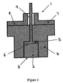
- FIG. 1 is a cross-section view of a sensor according to a first embodiment of the present invention
- FIG. 2 is a cross-section view showing how the sensor of FIG. 1 can be connected to a coaxial transmission cable in a first orientation
- FIG. 3 is a cross-section view showing how the sensor of FIG. 1 can be connected to a coaxial transmission cable in a second orientation;
- FIGS. 4 a and 4 b are cross-section views showing how the first electrically conductive bridge can be adapted to substantially surround the housing of the sensor of FIG. 1 ;
- FIG. 5 is a cross-section view of a sensor according to a second embodiment of the present invention.
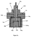
- FIG. 5 a is a cross-section view of a sensor according to a third embodiment of the present invention.
- FIG. 5 b is a cross-section view of a sensor according to a fourth embodiment of the present invention.
- FIG. 6 is a cross-section view showing how the sensor of FIG. 5 can be connected to a triaxial transmission cable in a first orientation
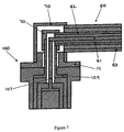
- FIG. 7 is a cross-section view showing how the sensor of FIG. 5 can be connected to a traxial transmission cable in a second orientation.
- a “coaxial” sensor 1 has a cylindrical electrode 2 formed from an electrically conductive ceramic material. A front face 3 of the electrode 2 is directed toward a stationary or passing object (not shown). The electrode 2 is located within and bonded to a housing 4 formed from an electrically non-conductive ceramic material.
- the electrically conductive and electrically non-conductive ceramic materials are chosen so that they have a similar thermal expansion coefficient and the sensor 1 remains virtually stress free at high operating temperatures.
- a front bridge piece 5 is located within the housing 4 and is bonded to a rear face 6 of the electrode 2 .
- a rear bridge piece 7 is bonded to a rear face 8 of the housing 4 .
- the front bridge piece 5 passes through apertures provided in the housing 4 and the rear bridge piece 7 to extend beyond the rear bridge piece.
- the aperture provided in the rear bridge piece 7 is wider than the front bridge piece 5 so that the two bridge pieces are separated by an annular air gap 9 .
- the front and rear bridge pieces 5 and 7 are connected to the two concentric conductors of a mineral insulated coaxial transmission cable 20 as shown in FIG. 2 .
- the transmission cable 20 has a central conductor 21 and an outer conductor 22 separated by a mineral insulating layer 23 .
- An electrically conductive cylindrical adaptor 30 is used to join the front bridge piece 5 to the central conductor 21 at a common interface 24 and the rear bridge piece 7 to the outer conductor 22 .
- the electrically conductive adaptor 40 shown in FIG. 3 can be used.
- the adaptor 40 is designed to receive the transmission cable 20 such that central and outer conductors 21 and 22 are connected substantially at right angles to the front and rear bridge pieces 5 and 7 and the centreline of the sensor 1 .
- the use of the adaptor 30 , 40 means that the “coaxial” sensor 1 can be fully assembled and tested before being connected to the transmission cable 20 . It also means that the front and rear bridges pieces 5 and 7 and the central and outer conductors 21 and 22 are connected together at a low-temperature region or the sensor 1 .
- the rear bridge piece 7 is formed on the rear face 8 of the housing 4 only.
- the rear bridge piece 7 can also extend along part or all of the side face 10 of the housing 4 as shown in FIGS. 4 a and 4 b.
- the “coaxial” sensor 1 is mounted so that the front face 3 of the electrode 2 is directed toward the stationary or passing object.
- the electrode 2 is energised by a signal transmitted along the central conductor 21 of the transmission cable 20 so that it capacitively couples with the stationary or passing object.
- the changes in the capacitance detected by the electrode 2 are transmitted back along the central conductor 21 as voltage signals and converted into distance measurements so that the distance between the electrode and the stationary or passing object can be calculated.
- a “triaxial” sensor 100 has a cylindrical electrode 102 formed from an electrically conductive ceramic material.
- a front face 103 of the electrode 102 is directed toward a stationary or passing object (not shown).
- the electrode 102 is located within and bonded to an electrically non-conductive ceramic spacer 104 .
- the electrode 102 and the spacer 104 are located within and bonded to an electrically conductive ceramic shield 105 which isolates the electrode from any external electrical interference.
- the shield 105 is located within and bonded to a housing 106 formed from an electrically non-conductive ceramic material.
- the electrically conductive and electrically non-conductive ceramic materials are chosen so that they have a similar thermal expansion coefficient.
- a front bridge piece 107 is bonded to a rear face 108 of the electrode 102 .
- An intermediate bridge piece 109 is bonded to a rear face 110 of the shield 105 .
- a rear bridge piece 111 is bonded to a rear face 112 of the housing 106 .
- the intermediate bridge piece 109 passes through apertures provided in the housing 106 and the rear bridge piece 111 to extend beyond the rear bridge piece.
- the front bridge piece 107 passes through apertures provided in the spacer 104 , the shield 105 , the intermediate bridge piece 109 and the rear bridge piece 111 to extend beyond the intermediate bridge piece and the rear bridge piece.
- the aperture provided in the rear bridge piece 111 is wider than the intermediate bridge piece 109 so that the two bridge pieces are separated by an annular air gap 113 .
- the aperture provided in the intermediate bridge piece 109 is wider than the front bridge piece 107 so that the two bridge pieces are separated by an annular air gap 114 .
- the electrically conductive ceramic shield 105 shown in FIG. 5 can be replaced by a thin electrically conductive ceramic layer 105 a that is deposited onto the spacer 104 using conventional techniques.
- the ceramic layer 105 a contacts the intermediate bridge piece and functions in exactly the same way as the shield 105 .
- the use of a thin deposited ceramic layer 105 a allows the size of the spacer 104 to be increased with an improvement in the strength and robustness of the sensor. The resulting sensor is also easier to assemble because to the simplification in the overall sensor design.
- the electrically conductive ceramic shield 105 shown in FIG. 5 can be replaced by a thin electrically conductive ceramic or metallic layer 105 b that is deposited onto the inside surface of the electrically non-conductive outer housing 106 using conventional deposition techniques.
- the conductive layer 105 b contacts the intermediate bridge piece and functions in exactly the same way as the shield 105 .
- the use of a thin deposited conductive layer 105 b allows the size of the spacer to be increased with an improvement in the performance of the sensor.
- the sensor is also easier to assemble because of the simplification in the overall sensor design.
- the front, intermediate and rear bridge pieces 107 , 109 and 111 are connected to the three concentric conductors of a mineral insulated triaxial transmission cable 50 as shown in FIG. 6 .
- the transmission cable 50 has a central conductor 51 , an intermediate conductor 52 and an outer conductor 53 separated by mineral insulating layers 54 .
- An electrically conductive cylindrical adaptor 60 is used to join the front bridge piece 107 to the central conductor 51 at a common interface 55 , the intermediate bridge piece 109 to the intermediate conductor 52 and the rear bridge piece 111 to the outer conductor 53 .
- the electrically conductive adaptor 70 shown in FIG. 7 can be used.
- the adaptor 70 is designed to receive the transmission cable 50 such that the central, intermediate and outer conductors 51 , 52 and 53 are connected substantially at right angles to the front, intermediate and rear bridge pieces 107 , 109 and 111 and the centreline of the sensor 100 .
- the “triaxial” sensor 100 has the same technical advantages and may operate in the same way as the “coaxial” sensor 1 described above. It will be readily appreciated that different measurement electronics can be used with the “coaxial” and “triaxial” sensors.
Landscapes
- Physics & Mathematics (AREA)
- General Physics & Mathematics (AREA)
- Measurement Of Length, Angles, Or The Like Using Electric Or Magnetic Means (AREA)
- Spectrometry And Color Measurement (AREA)
- Measurement Of Mechanical Vibrations Or Ultrasonic Waves (AREA)
- Fire-Detection Mechanisms (AREA)
- Details Of Aerials (AREA)
- Arrangements For Transmission Of Measured Signals (AREA)
Abstract
Description
- 1. Technical Field
- The present invention relates to sensors, and in particular to sensors that can be used for capacitively measuring the distance to either a stationary or passing object.
- 2. Background Art
- In many industrial measurement applications there is a need for a sensor that can be used at high operating temperatures to measure the distance to either a stationary or passing object. A typical application is the measurement of clearance between the tip of a gas turbine engine blade and the surrounding casing. In this situation the operating temperature of the sensor can reach 1500° C. Other applications including molten metal and molten glass level measurement, for example, have similar operating temperature requirements.
- U.S. Pat. No. 5,760,593 (BICC plc) describes a conventional sensor having a metal or metal-coated ceramic electrode that couples capacitively with the stationary or passing object. The electrode is connected directly to the centre conductor of a standard triaxial transmission cable and is surrounded by a metal shield and an outer housing. The metal shield and the outer housing are connected directly to the intermediate conductor and the outer conductor of the triaxial transmission cable respectively. Electrical insulation is provided between the electrode and the shield and also between the shield and the housing. The insulation can be in the form of machined ceramic spacers or deposited ceramic layers.
- One problem with these conventional sensors is that they utilise an alternating combination of metal and ceramic materials. As the operating temperature o:f the sensor increases, the metal components tend to expand more than the ceramic components. This often results in stress fractures forming in the ceramic spacers or layers, which reduce their electrical performance and may even result in the disintegration or de-lamination of the ceramic components. Not only does this cause the sensor to fail electrically, but the disintegration or de-lamination of the ceramic components also allows the metal components to vibrate and this can result in the mechanical failure of the complete sensor assembly.
- Gas turbine engine manufacturers now require an operating lifetime of at least 20,000 hours for sensors that are to be fitted to production models. Although conventional sensors have been successfully used at high operating temperatures for short periods of time, it is unlikely that they will ever be able to meet the required operating lifetime because of the inherent weakness of the sensor assembly caused by the different thermal expansion properties of the metal and ceramic components.
- A further problem is the way in which the electrode, shield and outer housing are connected to the transmission cable. With conventional sensor designs, the conductors of the transmission cable are directly connected to the electrode, shield and outer housing at a high temperature region (i.e. a part of the sensor that reaches an elevated temperature in use). Many types of transmission cables (in particular those where the conductors are insulated using mineral compounds) cannot be used at high temperatures and often fail after a short period of time. Furthermore, some conventional sensors do not have a hermetic seal between the transmission cable and the rest of the sensor assembly. This can allow moisture to penetrate the sensor assembly and reduce the performance of the sensor.
- The present invention provides a sensor for capacitively measuring the distance to a stationary or passing object, comprising an electrically conductive ceramic electrode for capacitively coupling with the object, and a housing that substantially surrounds the electrode.
- Because the electrode is formed from an electrically conductive ceramic, the sensor can be used at higher operating temperatures than conventional sensors that use metal or metal-coated ceramic electrodes. The housing is preferably formed from an electrically non-conductive ceramic and may be of any suitable shape or size to suit the installation requirements.
- To isolate the electrode from any external electrical interference, the sensor can further comprise a shield that substantially surrounds the electrode and is electrically isolated from the electrode by an insulating layer. The shield is can be formed from a solid piece of electrically conductive ceramic. However, the shield can also be a thin electrically conductive ceramic layer that is deposited onto the insulating layer using conventional deposition techniques. The use of a deposited ceramic layer greatly simplifies both the design of the sensor and subsequent assembly. The shield can also be a thin electrically conductive ceramic or metallic layer that is deposited onto the inside surface of the outer housing using conventional deposition techniques. The insulating layer is preferably formed as a machined electrically non-conductive ceramic spacer. The use of a ceramic layer with a similar coefficient of thermal expansion to both the insulating layer and the housing means that the coating will not tend to delaminate in service, which is possible with metallic coatings which have different thermal expansion characteristics.
- The electrically conductive ceramic and the non-electrically conductive ceramic are preferably selected to have similar thermal expansion coefficients so that the sensor assembly remains virtually stress free at high operating temperatures. The electrode and the shield can be formed from SiC and the insulating layer and the housing can be formed from SiN, for example. The electrode, shield and housing can be bonded together using standard diffusion bonding or vacuum braising methods to form an integral ceramic structure. The bonding provides a hermetic seal between the components that prevents the ingress of moisture into the sensor assembly and the transmission cable.
- The sensor can have a “captive” design so that if any of the ceramic components do fail for any reason then they are retained within the overall sensor assembly.
- Instead of joining the conductors of the transmission cable directly to the electrode and the housing at a high temperature region of the sensor, the conductors are preferably connected to electrically conductive bridges that are in turn connected to the electrode and the housing. The electrically conductive bridges extend away from the front face of the electrode (i.e. the face that faces toward the object in use) so that the connection between the conductors and the electrically conductive bridges takes place at a low temperature region at the rear of the sensor.
- If the sensor does not include a shield then a coaxial transmission cable having a central conductor and an outer conductor can be used. The central conductor is preferably connected to the electrode by means of a first electrically conductive bridge and the outer conductor is preferably connected to the housing by means of a second electrically conductive bridge. The first electrically conductive bridge preferably passes through apertures provided in the housing and the second electrically conductive bridge.
- The connection between the conductors and the electrically conductive bridges is preferably made using an adapter. The adapter can be shaped to accommodate a variety of different types and diameters of transmission cable. Furthermore, the adapter can connect the conductors to the electrically conductive bridges in a number of different orientations depending on the installation requirements of the sensor. For example, the conductors can be connected such that the transmission cable extends away from the front face of the electrode substantially parallel to the electrically conductive bridges. Alternatively, the conductors can be connected such that the transmission cable extends substantially at right angles to the electrically conductive bridges. Other orientations are also possible.
- If the sensor does include a shield then a triaxial transmission cable having a central conductor, an intermediate conductor and an outer conductor can be used. The central conductor is preferably connected to the electrode by means of a first electrically conductive bridge, the outer conductor is preferably connected to the housing by means of a second electrically conductive bridge and the intermediate conductor is preferably connected to the shield by means of a third electrically conductive bridge. The first electrically conductive bridge preferably passes through apertures provided in the insulating layer, the shield, the third electrically conductive bridge, the housing and the second electrically conductive bridge. Similarly, the third electrically conductive bridge preferably passes through aperture provided in the housing and the second electrically conductive bridge.
- The electrically conductive bridges can be formed from metal or electrically conductive ceramic and are preferably connected to the electrode, housing and shield using standard diffusion bonding or vacuum braising methods. Although it is generally preferred that the bridges are formed from electrically conductive ceramic, metal bridges can be used because they are connected to the electrode, shield and housing at an intermediate temperature region and so do not suffer significantly from the problems of thermal expansion. The electrically conductive bridges can be made in any size or shape depending on the design and installation requirements of the sensor.
- An adapter is preferably provided to connect the second and third electrically conductive bridges to the outer and intermediate conductors, as described above. The second electrically conductive bridge can substantially surround the housing such that it extends a part or all of the way along the side face of the housing. However, it is generally preferred that the shield, the insulating layer, the housing and the second electrically conductive bridge do not extend along the front face of the electrode.
- The use of electrically conductive bridges means that the sensor assembly can be manufactured and tested before it is connected to the transmission cable using an adaptor. This is not possible with conventional sensors where the transmission cable has to be directly connected to the electrode, housing and shield during the assembly process.
- The electrically conductive bridges can also be used with conventional sensors and those that utilise metal/ceramic and plastics/metal components.
-
FIG. 1 is a cross-section view of a sensor according to a first embodiment of the present invention; -
FIG. 2 is a cross-section view showing how the sensor ofFIG. 1 can be connected to a coaxial transmission cable in a first orientation; -
FIG. 3 is a cross-section view showing how the sensor ofFIG. 1 can be connected to a coaxial transmission cable in a second orientation; -
FIGS. 4 a and 4 b are cross-section views showing how the first electrically conductive bridge can be adapted to substantially surround the housing of the sensor ofFIG. 1 ; -
FIG. 5 is a cross-section view of a sensor according to a second embodiment of the present invention; -
FIG. 5 a is a cross-section view of a sensor according to a third embodiment of the present invention; -
FIG. 5 b is a cross-section view of a sensor according to a fourth embodiment of the present invention; -
FIG. 6 is a cross-section view showing how the sensor ofFIG. 5 can be connected to a triaxial transmission cable in a first orientation; and -
FIG. 7 is a cross-section view showing how the sensor ofFIG. 5 can be connected to a traxial transmission cable in a second orientation. - With reference to
FIG. 1 , a “coaxial” sensor 1 has acylindrical electrode 2 formed from an electrically conductive ceramic material. Afront face 3 of theelectrode 2 is directed toward a stationary or passing object (not shown). Theelectrode 2 is located within and bonded to ahousing 4 formed from an electrically non-conductive ceramic material. The electrically conductive and electrically non-conductive ceramic materials are chosen so that they have a similar thermal expansion coefficient and the sensor 1 remains virtually stress free at high operating temperatures. - A
front bridge piece 5 is located within thehousing 4 and is bonded to arear face 6 of theelectrode 2. Arear bridge piece 7 is bonded to arear face 8 of thehousing 4. Thefront bridge piece 5 passes through apertures provided in thehousing 4 and therear bridge piece 7 to extend beyond the rear bridge piece. The aperture provided in therear bridge piece 7 is wider than thefront bridge piece 5 so that the two bridge pieces are separated by an annular air gap 9. - The front and
rear bridge pieces coaxial transmission cable 20 as shown inFIG. 2 . Thetransmission cable 20 has acentral conductor 21 and anouter conductor 22 separated by amineral insulating layer 23. An electrically conductivecylindrical adaptor 30 is used to join thefront bridge piece 5 to thecentral conductor 21 at acommon interface 24 and therear bridge piece 7 to theouter conductor 22. Alternatively, the electricallyconductive adaptor 40 shown inFIG. 3 can be used. Theadaptor 40 is designed to receive thetransmission cable 20 such that central andouter conductors rear bridge pieces - It will be readily appreciated that the use of the
adaptor transmission cable 20. It also means that the front andrear bridges pieces outer conductors - In FIGS. 1 to 3, the
rear bridge piece 7 is formed on therear face 8 of thehousing 4 only. However, therear bridge piece 7 can also extend along part or all of theside face 10 of thehousing 4 as shown inFIGS. 4 a and 4 b. - In operation, the “coaxial” sensor 1 is mounted so that the
front face 3 of theelectrode 2 is directed toward the stationary or passing object. Theelectrode 2 is energised by a signal transmitted along thecentral conductor 21 of thetransmission cable 20 so that it capacitively couples with the stationary or passing object. The changes in the capacitance detected by theelectrode 2 are transmitted back along thecentral conductor 21 as voltage signals and converted into distance measurements so that the distance between the electrode and the stationary or passing object can be calculated. - With reference to
FIG. 5 , a “triaxial”sensor 100 has acylindrical electrode 102 formed from an electrically conductive ceramic material. Afront face 103 of theelectrode 102 is directed toward a stationary or passing object (not shown). Theelectrode 102 is located within and bonded to an electrically non-conductiveceramic spacer 104. Theelectrode 102 and thespacer 104 are located within and bonded to an electrically conductiveceramic shield 105 which isolates the electrode from any external electrical interference. Theshield 105 is located within and bonded to ahousing 106 formed from an electrically non-conductive ceramic material. The electrically conductive and electrically non-conductive ceramic materials are chosen so that they have a similar thermal expansion coefficient. - A
front bridge piece 107 is bonded to arear face 108 of theelectrode 102. Anintermediate bridge piece 109 is bonded to arear face 110 of theshield 105. Arear bridge piece 111 is bonded to arear face 112 of thehousing 106. Theintermediate bridge piece 109 passes through apertures provided in thehousing 106 and therear bridge piece 111 to extend beyond the rear bridge piece. Thefront bridge piece 107 passes through apertures provided in thespacer 104, theshield 105, theintermediate bridge piece 109 and therear bridge piece 111 to extend beyond the intermediate bridge piece and the rear bridge piece. The aperture provided in therear bridge piece 111 is wider than theintermediate bridge piece 109 so that the two bridge pieces are separated by anannular air gap 113. Similarly, the aperture provided in theintermediate bridge piece 109 is wider than thefront bridge piece 107 so that the two bridge pieces are separated by anannular air gap 114. - With reference to
FIG. 5 a, the electrically conductiveceramic shield 105 shown inFIG. 5 can be replaced by a thin electrically conductive ceramic layer 105 a that is deposited onto thespacer 104 using conventional techniques. The ceramic layer 105 a contacts the intermediate bridge piece and functions in exactly the same way as theshield 105. The use of a thin deposited ceramic layer 105 a allows the size of thespacer 104 to be increased with an improvement in the strength and robustness of the sensor. The resulting sensor is also easier to assemble because to the simplification in the overall sensor design. - With reference to
FIG. 5 b, the electrically conductiveceramic shield 105 shown inFIG. 5 can be replaced by a thin electrically conductive ceramic or metallic layer 105 b that is deposited onto the inside surface of the electrically non-conductiveouter housing 106 using conventional deposition techniques. The conductive layer 105 b contacts the intermediate bridge piece and functions in exactly the same way as theshield 105. The use of a thin deposited conductive layer 105 b allows the size of the spacer to be increased with an improvement in the performance of the sensor. The sensor is also easier to assemble because of the simplification in the overall sensor design. - The front, intermediate and
rear bridge pieces triaxial transmission cable 50 as shown inFIG. 6 . Thetransmission cable 50 has acentral conductor 51, anintermediate conductor 52 and anouter conductor 53 separated by mineral insulating layers 54. An electrically conductivecylindrical adaptor 60 is used to join thefront bridge piece 107 to thecentral conductor 51 at acommon interface 55, theintermediate bridge piece 109 to theintermediate conductor 52 and therear bridge piece 111 to theouter conductor 53. Alternatively, the electricallyconductive adaptor 70 shown inFIG. 7 can be used. Theadaptor 70 is designed to receive thetransmission cable 50 such that the central, intermediate andouter conductors rear bridge pieces sensor 100. - The “triaxial”
sensor 100 has the same technical advantages and may operate in the same way as the “coaxial” sensor 1 described above. It will be readily appreciated that different measurement electronics can be used with the “coaxial” and “triaxial” sensors.
Claims (16)
Applications Claiming Priority (3)
| Application Number | Priority Date | Filing Date | Title |
|---|---|---|---|
| GB0322655A GB2406381B (en) | 2003-09-27 | 2003-09-27 | Sensors |
| GB0322655.2 | 2003-09-27 | ||
| PCT/GB2004/003020 WO2005031250A1 (en) | 2003-09-27 | 2004-07-12 | Sensor for capacitively measuring the distance to an object |
Publications (2)
| Publication Number | Publication Date |
|---|---|
| US20070108050A1 true US20070108050A1 (en) | 2007-05-17 |
| US7414415B2 US7414415B2 (en) | 2008-08-19 |
Family
ID=29286952
Family Applications (1)
| Application Number | Title | Priority Date | Filing Date |
|---|---|---|---|
| US10/573,695 Expired - Fee Related US7414415B2 (en) | 2003-09-27 | 2004-07-12 | Sensors |
Country Status (9)
| Country | Link |
|---|---|
| US (1) | US7414415B2 (en) |
| EP (1) | EP1664669B1 (en) |
| JP (1) | JP4600778B2 (en) |
| CN (1) | CN100374814C (en) |
| AT (1) | ATE354781T1 (en) |
| DE (1) | DE602004004909T2 (en) |
| ES (1) | ES2282878T3 (en) |
| GB (1) | GB2406381B (en) |
| WO (1) | WO2005031250A1 (en) |
Cited By (5)
| Publication number | Priority date | Publication date | Assignee | Title |
|---|---|---|---|---|
| US20110006791A1 (en) * | 2008-01-30 | 2011-01-13 | Mtu Aero Engines Gmbh | Probe for a capacitive sensor device and gap-measuring system |
| EP2442077A1 (en) * | 2010-10-12 | 2012-04-18 | Future Technology (Sensors) Ltd | Sensor assemblies |
| US20120177811A1 (en) * | 2011-01-06 | 2012-07-12 | General Electric Company | Method for manufacturing a corrosion sensor |
| US20180035897A1 (en) * | 2015-03-04 | 2018-02-08 | Microlife Corporation | Infrared thermometer |
| US10641595B2 (en) * | 2018-04-09 | 2020-05-05 | United Technologies Corporation | Low profile triaxial blade tip clearance probe assembly with driven guard |
Families Citing this family (8)
| Publication number | Priority date | Publication date | Assignee | Title |
|---|---|---|---|---|
| US20090015271A1 (en) * | 2003-09-27 | 2009-01-15 | Future Technology (Sensors) Limited | Sensors |
| JP4736693B2 (en) * | 2005-10-12 | 2011-07-27 | 株式会社Ihi | Film thickness measuring apparatus and method |
| US7787945B2 (en) | 2006-03-08 | 2010-08-31 | Neuropace, Inc. | Implantable seizure monitor |
| GB0621620D0 (en) | 2006-10-31 | 2006-12-06 | Rolls Royce Plc | A sensor |
| US8093913B2 (en) | 2008-04-24 | 2012-01-10 | Ihi Corporation | Film thickness measurement device and method |
| DE102009060002A1 (en) * | 2009-12-21 | 2011-06-22 | Micro-Epsilon Messtechnik GmbH & Co. KG, 94496 | sensor |
| CN103673863A (en) * | 2013-12-03 | 2014-03-26 | 浙江中欣动力测控技术有限公司 | Capacitive sensor |
| GB2544751B (en) * | 2015-11-24 | 2017-11-22 | Future Tech (Sensors) Ltd | Multi-Layer Electrically Conductive Sensors |
Citations (13)
| Publication number | Priority date | Publication date | Assignee | Title |
|---|---|---|---|---|
| US3921805A (en) * | 1972-10-10 | 1975-11-25 | Newton L Compere | Rupturable blister pill package with safety backing |
| US4128776A (en) * | 1976-11-29 | 1978-12-05 | The United States Of America As Represented By The United States Department Of Energy | Magnetohydrodynamic electrode |
| US4294361A (en) * | 1979-04-09 | 1981-10-13 | Sterling Drug, Inc. | Push and peel blister strip packages |
| US4604905A (en) * | 1983-01-18 | 1986-08-12 | Rheometron A.G. | Measured-value sensors for magnetic-inductive flowmeters |
| US5101165A (en) * | 1990-05-29 | 1992-03-31 | General Electric Company | Electrical capacitance clearanceometer |
| US5247837A (en) * | 1991-09-25 | 1993-09-28 | Rosemount Inc. | Magnetic flowmeter electrode |
| US5270664A (en) * | 1990-10-03 | 1993-12-14 | Renishaw, Plc | Probe for measuring surface roughness by sensing fringe field capacitance effects |
| US5760593A (en) * | 1996-02-14 | 1998-06-02 | Bicc Public Limited Company | Gap measurement device |
| US5944191A (en) * | 1998-01-14 | 1999-08-31 | Fuisz Technologies Ltd. | Peelable entry-resistant package |
| US5973502A (en) * | 1996-06-26 | 1999-10-26 | Thermacoax Sas | Capacitive sensor including a coaxial cable and a probe |
| US6171460B1 (en) * | 1993-05-10 | 2001-01-09 | John L. Bill | Chemically protected electrode system |
| US6374680B1 (en) * | 1999-03-24 | 2002-04-23 | Endress + Hauser Gmbh + Co. | Capacitive pressure sensor or capacitive differential pressure sensor |
| US6465271B1 (en) * | 1998-07-07 | 2002-10-15 | Wen H. Ko | Method of fabricating silicon capacitive sensor |
Family Cites Families (15)
| Publication number | Priority date | Publication date | Assignee | Title |
|---|---|---|---|---|
| US3628136A (en) * | 1969-09-05 | 1971-12-14 | Garrett Corp | Means for measuring clearances in a gas turbine including a coaxial cable capacitor |
| US3805150A (en) * | 1970-08-17 | 1974-04-16 | Ade Corp | Environment immune high precision capacitive gauging system |
| DE3433351C1 (en) * | 1984-09-11 | 1986-01-02 | MTU Motoren- und Turbinen-Union München GmbH, 8000 München | Capacitive measuring system for measuring the distance between two parts that are movable relative to each other |
| JPS6228617A (en) * | 1985-07-31 | 1987-02-06 | Toshiba Corp | Measuring tube for electromagnetic flow meter and its production |
| DE3617373A1 (en) * | 1986-05-23 | 1987-11-26 | Mtu Muenchen Gmbh | CAPACITIVE MEASURING SYSTEM |
| GB2204693B (en) * | 1987-05-14 | 1991-02-13 | Rolls Royce Plc | Turbomachine tip clearance sensor |
| JPH01158320A (en) * | 1987-12-16 | 1989-06-21 | Kobe Steel Ltd | Molten metal detecting sensor in metal mold |
| FR2629196B1 (en) * | 1988-03-25 | 1991-05-31 | Thermocoax Cie | CAPACITIVE SENSOR |
| JPH0610256Y2 (en) * | 1988-05-07 | 1994-03-16 | 横河電機株式会社 | Ceramic electromagnetic flowmeter |
| GB2225855B (en) * | 1988-11-05 | 1993-01-20 | Rolls Royce Plc | Capacitance probe |
| JPH02171626A (en) * | 1988-12-26 | 1990-07-03 | Tanaka Kikinzoku Kogyo Kk | Shield type temperature sensor |
| US5166626A (en) * | 1990-05-29 | 1992-11-24 | General Electric Company | Electrical capacitance clearanceometer |
| JP2540253B2 (en) * | 1991-08-06 | 1996-10-02 | 品川白煉瓦株式会社 | Conductivity measurement cell |
| FR2721105B1 (en) * | 1994-06-09 | 1996-08-14 | Onera (Off Nat Aerospatiale) | Capacitive sensor with concentric electrodes and its manufacturing process. |
| GB9608111D0 (en) * | 1996-04-19 | 1996-06-26 | Bicc Plc | Gap Measurement Device |
-
2003
- 2003-09-27 GB GB0322655A patent/GB2406381B/en not_active Expired - Fee Related
-
2004
- 2004-07-12 EP EP04743361A patent/EP1664669B1/en not_active Expired - Lifetime
- 2004-07-12 CN CNB2004800278952A patent/CN100374814C/en not_active Expired - Fee Related
- 2004-07-12 US US10/573,695 patent/US7414415B2/en not_active Expired - Fee Related
- 2004-07-12 DE DE602004004909T patent/DE602004004909T2/en not_active Expired - Lifetime
- 2004-07-12 AT AT04743361T patent/ATE354781T1/en not_active IP Right Cessation
- 2004-07-12 ES ES04743361T patent/ES2282878T3/en not_active Expired - Lifetime
- 2004-07-12 JP JP2006527452A patent/JP4600778B2/en not_active Expired - Fee Related
- 2004-07-12 WO PCT/GB2004/003020 patent/WO2005031250A1/en not_active Ceased
Patent Citations (13)
| Publication number | Priority date | Publication date | Assignee | Title |
|---|---|---|---|---|
| US3921805A (en) * | 1972-10-10 | 1975-11-25 | Newton L Compere | Rupturable blister pill package with safety backing |
| US4128776A (en) * | 1976-11-29 | 1978-12-05 | The United States Of America As Represented By The United States Department Of Energy | Magnetohydrodynamic electrode |
| US4294361A (en) * | 1979-04-09 | 1981-10-13 | Sterling Drug, Inc. | Push and peel blister strip packages |
| US4604905A (en) * | 1983-01-18 | 1986-08-12 | Rheometron A.G. | Measured-value sensors for magnetic-inductive flowmeters |
| US5101165A (en) * | 1990-05-29 | 1992-03-31 | General Electric Company | Electrical capacitance clearanceometer |
| US5270664A (en) * | 1990-10-03 | 1993-12-14 | Renishaw, Plc | Probe for measuring surface roughness by sensing fringe field capacitance effects |
| US5247837A (en) * | 1991-09-25 | 1993-09-28 | Rosemount Inc. | Magnetic flowmeter electrode |
| US6171460B1 (en) * | 1993-05-10 | 2001-01-09 | John L. Bill | Chemically protected electrode system |
| US5760593A (en) * | 1996-02-14 | 1998-06-02 | Bicc Public Limited Company | Gap measurement device |
| US5973502A (en) * | 1996-06-26 | 1999-10-26 | Thermacoax Sas | Capacitive sensor including a coaxial cable and a probe |
| US5944191A (en) * | 1998-01-14 | 1999-08-31 | Fuisz Technologies Ltd. | Peelable entry-resistant package |
| US6465271B1 (en) * | 1998-07-07 | 2002-10-15 | Wen H. Ko | Method of fabricating silicon capacitive sensor |
| US6374680B1 (en) * | 1999-03-24 | 2002-04-23 | Endress + Hauser Gmbh + Co. | Capacitive pressure sensor or capacitive differential pressure sensor |
Cited By (10)
| Publication number | Priority date | Publication date | Assignee | Title |
|---|---|---|---|---|
| US20110006791A1 (en) * | 2008-01-30 | 2011-01-13 | Mtu Aero Engines Gmbh | Probe for a capacitive sensor device and gap-measuring system |
| US8513960B2 (en) * | 2008-01-30 | 2013-08-20 | Mtu Aero Engines Gmbh | Probe for a capacitive sensor device and gap-measuring system |
| EP2442077A1 (en) * | 2010-10-12 | 2012-04-18 | Future Technology (Sensors) Ltd | Sensor assemblies |
| US9372204B2 (en) | 2010-10-12 | 2016-06-21 | Future Technology (Sensors) Ltd | Sensor assemblies |
| US20120177811A1 (en) * | 2011-01-06 | 2012-07-12 | General Electric Company | Method for manufacturing a corrosion sensor |
| US9297742B2 (en) * | 2011-01-06 | 2016-03-29 | General Electric Company | Method for manufacturing a corrosion sensor |
| US20180035897A1 (en) * | 2015-03-04 | 2018-02-08 | Microlife Corporation | Infrared thermometer |
| EP3266370A4 (en) * | 2015-03-04 | 2018-12-05 | Microlife Corporation | Infrared thermometer |
| US10426355B2 (en) * | 2015-03-04 | 2019-10-01 | Microlife Corporation | Infrared thermometer |
| US10641595B2 (en) * | 2018-04-09 | 2020-05-05 | United Technologies Corporation | Low profile triaxial blade tip clearance probe assembly with driven guard |
Also Published As
| Publication number | Publication date |
|---|---|
| CN100374814C (en) | 2008-03-12 |
| JP2007506958A (en) | 2007-03-22 |
| WO2005031250A1 (en) | 2005-04-07 |
| DE602004004909T2 (en) | 2007-10-31 |
| GB2406381A (en) | 2005-03-30 |
| EP1664669A1 (en) | 2006-06-07 |
| JP4600778B2 (en) | 2010-12-15 |
| GB2406381B (en) | 2005-10-12 |
| US7414415B2 (en) | 2008-08-19 |
| DE602004004909D1 (en) | 2007-04-05 |
| CN1856689A (en) | 2006-11-01 |
| EP1664669B1 (en) | 2007-02-21 |
| ES2282878T3 (en) | 2007-10-16 |
| ATE354781T1 (en) | 2007-03-15 |
| GB0322655D0 (en) | 2003-10-29 |
Similar Documents
| Publication | Publication Date | Title |
|---|---|---|
| US20090015271A1 (en) | Sensors | |
| US7414415B2 (en) | Sensors | |
| JP6644683B2 (en) | Advanced radio frequency sensing probe | |
| EP2627975B1 (en) | Sensor assemblies | |
| US8141429B2 (en) | High temperature capacitive static/dynamic pressure sensors and methods of making the same | |
| US20120138361A1 (en) | Cable Terminator Assemblies | |
| JPH0332185B2 (en) | ||
| CN106404267B (en) | Pressure sensor | |
| KR20170015252A (en) | Piezoelectric pressure sensor and process of manufacturing said piezoelectric pressure sensor | |
| SE442783B (en) | CAPACITIVE VALUE RECEIVER | |
| CN108700436B (en) | Multilayer conductive sensor | |
| CN108369244B (en) | Acceleration measuring device and method for producing such an acceleration measuring device | |
| EP0256846A2 (en) | Jet engine gas path condition monitoring | |
| CN108291926B (en) | Accelerometer and method of making the same | |
| CN112415226A (en) | High-temperature-resistant ground insulation type acceleration sensor | |
| CN115940076B (en) | A smart GIS terminal with built-in multi-point temperature monitoring | |
| GB2225855A (en) | Capacitance probe | |
| JP6835028B2 (en) | Airtight terminal and sensor unit | |
| CN221782284U (en) | A piezoelectric acceleration sensor | |
| EP4276403B1 (en) | Clearance sensor | |
| CN211317399U (en) | Composite sensor | |
| SU1241334A1 (en) | High-frequency coaxial electric connector assembly | |
| JPH0564344A (en) | Method of detecting interfacial pressure of prefabricated junction box for CV cable | |
| CN114323444A (en) | High-temperature-resistant sealed cavity testing device and configuration method | |
| JPH0530630A (en) | Prefab joint incorporating sensor |
Legal Events
| Date | Code | Title | Description |
|---|---|---|---|
| AS | Assignment |
Owner name: FUTURE TECHNOLOGY (R&D) LTD., GREAT BRITAIN Free format text: ASSIGNMENT OF ASSIGNORS INTEREST;ASSIGNOR:ELLIOTT, HOWARD;REEL/FRAME:018032/0280 Effective date: 20060428 Owner name: FUTURE TECHNOLOGY (R&D) LTD.,GREAT BRITAIN Free format text: ASSIGNMENT OF ASSIGNORS INTEREST;ASSIGNOR:ELLIOTT, HOWARD;REEL/FRAME:018032/0280 Effective date: 20060428 |
|
| STCF | Information on status: patent grant |
Free format text: PATENTED CASE |
|
| FPAY | Fee payment |
Year of fee payment: 4 |
|
| FPAY | Fee payment |
Year of fee payment: 8 |
|
| FEPP | Fee payment procedure |
Free format text: PAT HOLDER NO LONGER CLAIMS SMALL ENTITY STATUS, ENTITY STATUS SET TO UNDISCOUNTED (ORIGINAL EVENT CODE: STOL); ENTITY STATUS OF PATENT OWNER: LARGE ENTITY |
|
| AS | Assignment |
Owner name: FUTURE TECHNOLOGY (SENSORS) LIMITED, UNITED KINGDO Free format text: ASSIGNMENT OF ASSIGNORS INTEREST;ASSIGNOR:FUTURE TECHNOLOGY (R&D) LIMITED;REEL/FRAME:041584/0469 Effective date: 20080520 |
|
| FEPP | Fee payment procedure |
Free format text: MAINTENANCE FEE REMINDER MAILED (ORIGINAL EVENT CODE: REM.); ENTITY STATUS OF PATENT OWNER: LARGE ENTITY |
|
| LAPS | Lapse for failure to pay maintenance fees |
Free format text: PATENT EXPIRED FOR FAILURE TO PAY MAINTENANCE FEES (ORIGINAL EVENT CODE: EXP.); ENTITY STATUS OF PATENT OWNER: LARGE ENTITY |
|
| STCH | Information on status: patent discontinuation |
Free format text: PATENT EXPIRED DUE TO NONPAYMENT OF MAINTENANCE FEES UNDER 37 CFR 1.362 |
|
| FP | Lapsed due to failure to pay maintenance fee |
Effective date: 20200819 |