US20060270312A1 - Interactive animated characters - Google Patents
Interactive animated characters Download PDFInfo
- Publication number
- US20060270312A1 US20060270312A1 US11/140,483 US14048305A US2006270312A1 US 20060270312 A1 US20060270312 A1 US 20060270312A1 US 14048305 A US14048305 A US 14048305A US 2006270312 A1 US2006270312 A1 US 2006270312A1
- Authority
- US
- United States
- Prior art keywords
- mouth
- assembly
- animating
- movement
- corners
- Prior art date
- Legal status (The legal status is an assumption and is not a legal conclusion. Google has not performed a legal analysis and makes no representation as to the accuracy of the status listed.)
- Abandoned
Links
Images


Classifications
-
- A—HUMAN NECESSITIES
- A63—SPORTS; GAMES; AMUSEMENTS
- A63H—TOYS, e.g. TOPS, DOLLS, HOOPS OR BUILDING BLOCKS
- A63H13/00—Toy figures with self-moving parts, with or without movement of the toy as a whole
- A63H13/005—Toy figures with self-moving parts, with or without movement of the toy as a whole with self-moving head or facial features
-
- A—HUMAN NECESSITIES
- A63—SPORTS; GAMES; AMUSEMENTS
- A63H—TOYS, e.g. TOPS, DOLLS, HOOPS OR BUILDING BLOCKS
- A63H3/00—Dolls
- A63H3/28—Arrangements of sound-producing means in dolls; Means in dolls for producing sounds
-
- A—HUMAN NECESSITIES
- A63—SPORTS; GAMES; AMUSEMENTS
- A63H—TOYS, e.g. TOPS, DOLLS, HOOPS OR BUILDING BLOCKS
- A63H3/00—Dolls
- A63H3/36—Details; Accessories
- A63H3/38—Dolls' eyes
- A63H3/40—Dolls' eyes movable
Definitions
- the present invention relates to interactive toys and, more particularly, to animated characters that can perform movements with body parts thereof in a precisely controlled and coordinated manner in response to external sensed conditions.
- a very compact animated character that provides highly life-like and intelligent seeming interaction with the user thereof.
- the animated character can take the form of a small animal-like creature having a variety of moving body parts including a smile/emotion assembly which are coordinated to exhibit life-like emotional states by precisely controlling and synchronizing their movements in response to external sensed conditions.
- the animated character also includes sound generating circuitry to generate speech sounds as well as sounds associated with various emotional states, which are coordinated with a lip sync assembly simulating speech mouth movement.
- the drive system utilizes first and second reversible motors which are able to power and precisely coordinate the lip sync assembly producing speech mouth movement, with the movable parts and the smile/emotion assembly to produce life-like interactions and emotional expressions.
- the drive system that powers the movement of the character body parts includes a mouth assembly on the front facial area including a flexible molded material having upper and lower mouth portions and having first and second opposing corners thereof.
- the animated character has a lip sync assembly to simulate speech mouth movement that is independently controlled and coordinated with the movable parts resulting in coordinated speech mouth movement with the desired life-like emotional states.
- a first mouth mechanism is operable with the mouth assembly for controlling the first and second corners of the mouth assembly to define smile/emotion states of the mouth assembly responsive to external input from sensed conditions of the plurality of sensors.
- a second mouth mechanism is further operable with the mouth assembly for controlling the upper and lower mouth portions to provide lip synchronism response to the multisyllabic words generated with the sound generating circuitry.
- the drive system that powers movement of the first and second mouth mechanisms thus uses each of these mechanisms independently to simulate life-like responses to sensed conditions, at least one of which may also be used for causing movement of another of movable body parts in addition to the first or second mechanisms.
- the cams have surfaces that are programmed for very precise and controlled movements of the body parts in particular ranges of shaft movements such that generally every point on a particular cam surface has meaning to the controller in terms of what type of movement the body part is undergoing and where it needs to be for its subsequent movement, or for when the body part is to remain stationary. In this manner, the controller can coordinate movements of the body parts to provide the animated character with different states such as sleeping, waking or excited states.
- the controller is provided with sound generating circuitry for generating words that complement the different states such as snoring in the sleeping state or various exclamations in the excited state.
- the programmed surfaces of the cam mechanisms are preferably provided on the walls of slots with the cam mechanisms including followers that ride in the slots.
- the animated character herein is also capable of playing games with the user in a highly interactive and intelligent seeming manner.
- FIG. 1 is a perspective view of the animated character body showing the various components thereof;
- FIGS. 2A, 2B and 2 C illustrate independently driven Lip Sync and Smile/emotion actuator linkages to simulate life-like responses in accordance with an embodiment of the invention
- FIGS. 3A and 3B illustrate controls activation of reversible motors to enable the animated character to exhibit speech and expression of emotional states simultaneously;
- FIGS. 4A and 4B illustrate mechanical cam and gear positioning and control including the left and right ear cam members respectively;
- FIG. 5 illustrates the animated character from a front elevational view to show emotional states of the mouth assembly
- FIG. 6 illustrates actuation of the upper and lower mouth portions of the mouth assembly and including a tongue member
- FIG. 7 illustrates positioning of plume, brow and eye assemblies, and the pinion gear of the ear assembly
- FIGS. 8 and 9 illustrate the gear train transmission portion of the drive system to show the optical counting assembly
- FIG. 10 illustrates the positioning of the movable body parts expressing various emotional states as the first control shaft rotates in a clockwise direction
- FIG. 11 shows a schematic block diagram of the embedded processor circuitry which includes information processing and voice speech synthesis functionality in accordance with the present invention.
- An animated character 100 as shown in FIGS. 1-4 has a number of movable parts, generally designated 102 , which are coordinated to exhibit life-like emotional states by precisely controlling and synchronizing their movements in response to external sensed conditions.
- the animated character 100 also has a lip sync assembly 140 to simulate speech mouth movement that is independently controlled and coordinated with the movable parts 102 resulting in seemingly intelligent and highly life-like interaction with the user.
- the animated character's lip sync assembly 140 and movable body parts 102 are controlled and coordinated in response to predetermined sensory inputs detected by various sensors, generally designated 104 (where in figures?).
- the sensors 104 signal a controller or processor circuitry 400 , described hereinafter, which controls a drive systems 106 for coordinating speech mouth movement with the desired life-like emotional states.
- the drive system 106 utilizes two, low power reversible electric motors, 108 & 110 , which are able to power and precisely control the lip sync assembly 140 and the movable parts 102 to produce life-like interactions and emotional expressions.
- the control processor circuitry 400 includes sound generating circuitry to generate speech sounds as well as sounds associated with various emotional states, such as a laugh, gasp, sigh, growl & snore, etc. coordinated with speech mouth movement driven by the lip sync assembly 140 and movement of the various body parts 102 of the animated character 100 .
- the animated character 100 includes a main body 112 which has a relatively small and compact form and which contains, in an interior thereof 114 , the drive system 106 and all the circuitry and various linkages for generating speech and sounds, and for activating the lip sync assembly 140 and moving body parts 102 in a coordinated manner for seemingly intelligent and life-like interaction with the user.
- the sensors 104 effectively detect predetermined external conditions and signal the control processor circuitry 400 of the animated character 100 which then controls activation of reversible motors 108 & 110 , as seen in FIGS. 3A &3B , to enable the animated character 100 to exhibit speech and expression of emotional states simultaneously.
- the animated character 100 responds to being held, petted, and tickled. The child can pet the animated character's tummy, rub its back, rock it, and play with it, e.g., via sensory input buttons. Whenever the child does these things, the animated character will speak and make sounds using the speech synthesizer.
- the movable body parts 102 of the animated character 100 herein are provided in a front facial area 117 toward the upper end 116 of the animated character body 112 .
- the facial area contains eye and eye lid assemblies 123 and 124 respectively and mouth assembly 126 , with a brow assembly 122 adjacent thereto, as seen in FIG. 1 .
- the movable body parts 102 of the animated character 100 herein also include an ear assembly 118 , including left and right movable ear devices 132 and 133 respectively, set apart from one another and adjacent the brow assembly 122 , and a plume assembly 120 also adjacent the brow assembly 122 and disposed generally between movable ear devices 132 and 133 .
- the animated character 100 also includes a movable chest assembly 128 toward a lower end 115 of the body 112 , and a movable foot assembly 130 adjacent thereto.
- a face frame 119 is mounted to the body 112 in an upper opening and includes a pair of upper eye openings and a lower mouth opening centered therebelow (openings not shown).
- An eye assembly 123 is provided including a pair of semi-spherical eyeballs 248 and 250 sized to fit in the eye openings of the frame 119 and pivotally attached thereto via pivot eye shafts 252 and 254 respectively.
- the pivot shafts 252 and 254 are spaced forwardly and vertically higher than a first control shaft 136 (discussed further below) and extends perpendicular thereto.
- Movement of each body part 102 is driven either by motor 108 , as seen in FIG. 3A , via a cam operating mechanism, generally designated 134 , or by motor 110 , as seen in FIGS. 2C and 3B , via a shuttle gear 142 .
- the cam operating mechanism 134 driven by motor 108 , rotates a first control shaft 136 fixed to the interior 114 of the main body 112 , and attached thereto are cam mechanisms, generally designated 138 .
- the first shaft 136 is rotated when the motor 108 is activated via gear train transmission 278 by meshing of worm gear 280 with peripheral teeth 282 a of a gear cam member 282 fixed on and for rotation with the first control shaft 136 , as seen in FIG. 4B .
- cam mechanisms 138 are associated with the ear assembly 118 , the plume assembly 120 , the brow assembly 122 , the eye lid assembly 124 , the eye assembly 125 , the smile/emotion assembly 126 , and the chest assembly 128 , coordinating the movement of the aforementioned assemblies for the expression of various life-like emotional states.
- motor 110 rotates the shuttle gear 142 associated with a second control shaft 139 in one direction driving movement of the lip sync assembly 140 simulating speech mouth movement, or rotates the shuttle gear 142 and associated second control shaft 139 in an opposite direction driving movement of the foot assembly 130 .
- the dual motor system of the present embodiment separates the lip sync assembly 140 operations from operations of the movable body parts 102 associated with the first control shaft 136 and cam operating mechanisms 138 .
- any speech generated by animated character 100 can be combined and coordinated with any of the exhibited life-like emotional states, such that the animated character 100 is able to coordinate the same speech with any exhibited emotional state, and likewise, coordinate different speech with the same emotional state.
- Cam mechanisms 138 each include a disc-shaped cam member and a follower or actuator linkage thereof. More specifically, and referencing FIG. 4B with respect to the ear assembly 118 , an ear cam mechanism 144 is provided including left and right ear cam members 146 and 150 respectively. Left ear cam member 146 (shared with left smile/emotion cam member as set forth herein) is fixed on shaft 136 , rotates about axis 136 a and has an arcuate slot 154 formed on one side thereof, defined by slot wall 156 and including programmed cam surfaces 156 a which engages a left ear cam follower 148 .
- a follower pin 158 projecting from left ear cam follower 148 rides in slot 154 against cam surfaces 156 a as shaft 136 is rotated by motor 108 .
- Left ear cam follower 148 has a window 160 through which shaft 136 extends and projects perpendicular to axis 136 a thereof.
- teeth 162 At an upper end of the follower 148 are teeth 162 for engagement with a pinion gear 164 (shown in FIG. 7 ) which also engages left movable ear device 132 , providing pivoting movement of left movable ear device 132 upon rotation of shaft 136 which generates vertical up and down movement of the follower member 148 .
- Right ear cam member 150 and follower 152 are fixed on shaft 136 at an end opposite left ear cam member 146 and follower 148 and engage and pivot right movable ear device 133 in the same manner though similar mechanisms as described herein for pivoting left movable ear device 132 .
- left and right movable ear devices 132 and 133 respectively are able to bend forward and back in addition to their pivoting action upon rotation of the control shaft 136 .
- left movable ear device 132 includes a flexible strip 166 that has a first surface 168 and second surface 170 and at least one plate 172 connected to each first and second surface 168 and 170 respectively.
- a first elongated device 174 made of a flexible material, intersects at least one plate 172 on the first surface 168 of device 132 and connects to a first lever on an ear actuator.
- the ear actuator Upon rotation of the shaft 136 , the ear actuator is rotated in a first direction about a drive axis fixed relative to the animated character body and connected to the first elongated device 174 engaging at least one plate 172 on the first surface 168 pulling the elongated device 174 toward the ear actuator thus bending forward the left movable ear device 132 .
- a second elongated device 176 also made of flexible material, intersects at least one plate 172 on the second surface 170 of device 132 and connects to a second lever on the ear actuator.
- second elongated device 176 engages at least one plate 172 on the second surface 170 and is pulled toward the ear actuator thus bending back the left movable ear device 132 .
- Right movable ear device 133 also bends forward and back upon rotation of control shaft 136 in the same manner through similar mechanisms as described herein for bending left movable ear device 132 .
- a prior form of a movable appendage was available from the Assignee herein for which prior issued U.S. Pat. No. 6,773,327 for “Apparatus for actuating a toy” to Felice et al. issued Aug. 10, 2004 to Applicant's Assignee is hereby incorporated by reference in its entirety with reference to apparatus for an appendage including a moveable device within a toy appendage that is attached to a body of a toy and an actuator connected to the moveable device.
- the actuator is configured to rotate the moveable device about a drive axis that is fixed relative to the body of the toy.
- the actuator is configured to rotate at least a first portion of the moveable device relative to at least a second portion of the moveable device about a device axis that is fixed relative to the moveable device.
- the mouth assembly 126 includes a first mouth mechanism herein the smile/emotion assembly 127 and a second mouth mechanism herein the lip sync assembly 140 which are operate with the mouth assembly 126 to independently drive two different types of mouth movement.
- the mouth assembly 126 has a mouth member 196 comprised of substantially identical upper and lower mouth portions 204 and 206 , covered with a flexible molded material, in the form of upper and lower halves of a beak in the present embodiment, as seen in FIGS. 2A and 2B .
- the molded flexible elastomeric mouth includes upper and lower lips having center portions and opposite side corners where the lips meet.
- the mouth has attachment points at the center portions and corners.
- the first animation mechanism provides for animating the mouth for simulated talking movement by moving the attachment points at the center portions.
- the second animating mechanism independent from the first animating mechanism, provides for moving the attachment points at the corners to simulate mouth movement corresponding to facial expression. Accordingly, the first and second animating mechanisms act to distort the elastomeric mouth to achieve simulated talking movement and facial expression as the animating mechanisms are operated and for providing simulated talking movement or facial expression, or a combination thereof as the animating mechanisms are operated. As discussed herein, the elastomeric mouth has a neutral undeformed position, wherein the second animating mechanism moves the attachment points at the corners to deform the elastomeric mouth from the neutral undeformed position.
- the smile/emotion assembly 127 attaches to left and right corners 198 and 200 respectfully, of the mouth member 196 to achieve a first type of mouth movement.
- the smile/emotion assembly 127 moves corners 198 and 200 of the mouth member 196 in a vertical up direction toward the upper end 116 of the main body 112 and a vertical down direction toward the lower end 115 of the main body, such that the mouth member 196 appears to smile, or frown, or neither, as seen in FIG. 5 .
- a smile/emotion cam mechanism 178 drives the vertical up and down movement of the smile/emotion assembly 127 and includes a left cam member 146 (shared with left ear cam member as set forth herein) and a right cam member 179 as shown in FIG. 4B .
- Left smile/emotion cam member 146 has an arcuate slot formed on a side opposite arcuate slot 154 , including programmed cam surfaces which engage a pin 186 of a left smile/emotion follower 184 as shaft 136 is rotated by motor 108 .
- Smile/emotion follower 184 is L-shaped and includes a first arm 188 with a window 190 through which shaft 136 extends, and a second arm 192 which projects forward substantially perpendicular to axis 136 a thereof.
- FIGS. 2A and 2B illustrate independently driven Lip Sync and Smile/emotion actuator linkages to simulate life-like responses.
- a distal end 193 of projected second arm 192 connects to a linkage 194 attached to the left corner 198 of the mouth member 196 moving the left corner 198 in a vertical up and down fashion upon rotation of shaft 136 .
- the right corner 200 of mouth member 196 is moved vertically up and down in synchronization with the left corner 198 in the same manner and through similar mechanisms as described for the left corner 198 of mouth member 196 .
- the mouth member 196 is able to change expressions between a smile, frown, and neutral states upon rotation of first control shaft 136 .
- FIG. 2C illustrates motor 110 driving movement of the foot assembly 130 through activation of the shuttle gear 142 and rotation of the second control shaft 139 in a direction opposite the rotation which drives the lip sync assembly 140 as well as discussed further below.
- Motor 110 activates shuttle gear 142 and associated second control shaft 139 driving the lip sync assembly 140 to open and close the mouth member 196 , such that the upper and lower mouth portions 204 and 206 respectively, move away from and toward each other in order to simulate speech mouth movement which is coordinated with speech sounds, by the control processor circuitry 400 .
- the mouth portions 204 and 206 include upper and lower pairs of oppositely facing hook-shaped coupling portions 216 to allow an associated actuator 218 , to cause opening and closing movement of the mouth portions 204 and 206 upon rotation of second control shaft 139 , as seen in FIG. 6 and discussed further below.
- both motors 108 and 110 activate at the same time, simultaneously achieving two types of mouth movement.
- the mouth member 192 coordinated by the control processor circuitry 400 according to predetermined conditions, seemingly appears to speak with coordinated speech mouth movement synchronized with the appropriate mouth expression such as a smile, frown or neutral state, providing seemingly intelligent interaction with the user.
- the upper and lower mouth portions 204 and 206 are pivotally mounted on shaft 208 by rear semi-circular boss portions thereof spaced on either side of the mouth portions 204 and 206 so as to provide space for a tongue member 210 therebetween, as seen in FIG. 6 .
- the tongue member 210 includes an intermediate annular bearing portion 212 through which the pivot shaft 208 extends and has a rearwardly extending switch actuator portion 214 so that depressing the tongue 210 pivots the portion 214 for actuating the tongue sensor assembly. Referring to FIG. 6 , the tongue sensor assembly is illustrated. As previously discussed, the tongue member 210 that has an actuator portion 214 that projects rearwardly and pivots.
- the switch actuator portion 214 extends further in the rearward direction than the forward tongue portion 210 and is designed so that normally the switch actuator portion 214 is in its lower position and the tongue portion 210 is disposed for activation to simulate feeding the animated character 100 .
- the eye lid assembly 124 as shown in FIG. 7 includes upper and lower lid portions 220 and 222 respectively, pivotally mounted on shaft 224 interconnecting the pair of eyelids.
- Assembly 124 has associated eye lid cam mechanism 226 which includes a cam member 228 fixed on shaft 136 having an arcuate slot 230 defined by slot walls 232 .
- An eyelid cam follower 234 includes a pin 236 projecting therefrom for engagement with cam surfaces 232 a on slot walls 232 .
- the cam follower 234 has a window 238 through which shaft 136 extends and projects forwardly from the shaft 136 substantially perpendicular to axis 136 a thereof.
- the eye assembly 123 has left and right eye balls 248 and 250 respectively, pivotally mounted on left and right eye shafts 252 and 254 respectively, and associated with barrel cam 146 mounted on first control shaft 136 .
- Shafts 252 and 254 fit into follower 255 which has shaft 257 that engages barrel cam 146 , for back and forth sideways movement of left and right eye balls 248 and 250 respectively, as first control shaft 136 is rotated.
- the plume assembly 120 and the brow assembly 122 are pivotally attached to a brow bracket 278 fixed to the upper end 116 of the body 112 .
- the plume assembly 120 as seen in FIGS. 1 and 7 has a plume member 256 which pivots about a shaft 258 and is associated with plume cam mechanism 260 including plume cam member 262 .
- Cam member 262 is fixed on shaft 136 and includes an arcuate slot 264 defined by slot walls 266 .
- Plume follower 268 includes a pin 270 projecting therefrom for engagement with slot surfaces 264 a on slot walls 264 .
- Plume follower 268 has a window 272 through which shaft 136 extends and projects upwardly from the shaft 136 substantially perpendicular to the axis 136 a thereof.
- a offset bent hook portion 274 At an upper end of follower 268 is a offset bent hook portion 274 having a shaft 276 for engagement with an end of plume member 256 , such that rotation of first control shaft 136 translates into a vertical up and down movement of follower 268 causing attached plume member 256 to pivot in a back and forth fashion.
- the brow assembly 122 as seen in FIGS. 1 and 7 has an eyebrow member 280 pivotally attached to brow bracket 278 and is associated with brow cam mechanism 283 including brow cam member 284 .
- Cam member 284 is fixed on shaft 136 and includes an arcuate slot 286 defined by slot walls 288 .
- Brow follower 290 includes a pin 292 projecting therefrom for engagement with slot surfaces 288 a on slot walls 288 .
- Brow follower 290 has a window 294 through which shaft 136 extends and projects upwardly from the shaft 136 substantially perpendicular to the axis 136 a thereof.
- a hook portion 296 having a shaft 298 for engagement with eyebrow member 280 , such that rotation of first shaft 136 translates into a vertical up and down movement of follower 290 causing attached eyebrow member 280 to pivot in a vertical up and down fashion.
- a chest assembly 128 includes an apertured disc actuator 320 having an upper arm portion 322 attached to a speaker/speaker grill 324 fixed to a chest portion 328 movably fixed to a bracket (not shown) which in turn is rigidly mounted to the animated character body 112 .
- the disc actuator 320 is made of a plastic material and the arm portion 322 thereof spaces the disc actuator 320 forwardly of the speaker grill 324 .
- the speaker grill 324 is preferably of a plastic material with arm portions thereof spaced forwardly allowing the disc actuator 320 to be flexibly and resiliently shifted or pushed back and forth.
- the chest assembly 128 is associated with cam mechanism 330 including cam member 332 fixed to first control shaft 136 , and follower 334 having a window 336 an end of the follower through which shaft 136 extends.
- follower 334 further includes a hook portion 338 at an end opposite the window 336 which couples to the chest portion 328 , such that the chest portion 328 moves in and out with respect to the character body 112 as the first control shaft 136 is rotated.
- the animated character 100 also includes a foot assembly 130 including a pair of feet 300 , as seen in FIG. 2C , that are movable relative to the animated character body 112 which allows the animated character to rock back and forth and, if done repetitively, gives the appearance that the animated character 100 is dancing.
- Motor 110 drives movement of the foot-assembly 130 through activation of the shuttle gear 142 and rotation of the second control shaft 139 in a direction opposite the rotation which drives the lip sync assembly 140 .
- the foot assembly 130 also includes a battery compartment (not shown). As the splined connection between the shaft and pinion portions allows for relative motion such as when a child grabs the feet 300 during movement thereof. It is possible for a particular shaft to become out of alignment, however the splined connection will allow subsequent movement of feet 300 in alignment with each other absent a braking force applied thereto.
- the control processor circuitry 400 is able to precisely control and determine the position of the first control shaft 136 when the motor 108 is activated; however, it is also desirable to avoid the expense and moving parts of utilizing a closed loop servo mechanism for providing the necessary feedback.
- the drive system 106 of an embodiment herein instead includes an optical counting assembly 302 which counts intervals of the rotation of a slotted gear wheel 304 in gear train transmission of the drive system 106 , as seen in FIGS. 8 and 9 .
- the gear wheel 304 is mounted at the lower end of a common vertical shaft 306 having worm gear 280 formed at its upper end, and is driven for rotation by the upper portion 308 a of intermediate compound gear 308 which, in turn, is driven for rotation by gear 108 a on the output shaft of the motor 108 which drives the larger lower portion 308 b of compound gear 308 for rotation.
- cam surfaces For programming of the cam surfaces, modeling of the animated character's different states is based on puppeteering actions to achieve positions of body parts for generating animated character movements. From the neutral position as a starting point, the cam is designed to actuate the leaf spring switch to zero out the count for the motor on a regular basis. In this manner, the position of the shaft will not become out of synchronization, the count of the processor thus being zeroed to provide for recurrent and regular calibration of the position of the shaft. From the neutral position, rotation/direction is determined to cause certain coordinated movements of various body parts with precise movements thereof.
- the cams are provided with cam surfaces that have active regions and inactive regions so that in the active regions, the part associated with the particular cam is undergoing movement, and in the inactive region the part is stationary.
- an integral IR transmitter element 312 facilitates optical servo control.
- the optical servo control circuitry employing the slotted wheel for generating an infrared light source is used.
- the phototransistor is used as an infrared photo detector for generating a light pulse count signal.
- the IR receiver element 314 is rigidly mounted to the frame of the box-shaped housing portion 314 thereof integrally formed with frame wall. In this manner, the optical counting assembly 302 herein is improved over prior feedback mechanisms that require moving parts or impart frictional resistance to motor operation, as the assembly 302 utilizes elements 312 and 314 that are fixed in the body interior using the optical servo control circuitry for controlling the operation of the motor.
- the control processor circuitry 400 can receive accurate information regarding the position of the control shaft 136 for precisely controlling the movements of the body parts 102 .
- Preferably six slots 310 are equally spaced at 60 degree intervals about the wheel 304 .
- an initialization switch assembly is provided mechanically affixed to a frame for the cam operating mechanism 134 to zero out the count in the control circuitry 400 on a regular basis when the switch assembly is actuated.
- the optical counter assembly counts intervals of the revolutions of an apertured gear wheel with the use of standard types of IR transmitters and receivers on either side thereof that are small components fixed in housings rigidly mounted inside the animated character 100 .
- a leaf spring switch is mounted between the disc 320 and the speaker grill 324 and affixed thereto.
- depressing the disc 320 as by pushing or rubbing on the hide of the character thereover causes engagement of the contact strips which signals the processor circuitry 400 .
- Actuating a front sensor assembly can simulate tickling of the animated character 100 in its belly region.
- cam surfaces of the cam mechanisms 138 herein are provided with precise predetermined shapes which are coordinated with the programming of the processor circuitry 400 so that at every point of the cam surfaces, the processor circuitry 400 can be used to determine the position of the moving body parts 102 associated therewith.
- the animated character 100 can be provided with a number of different expressions to simulate different predetermined physical and emotional states. For instance, changes in emotional expressions of animated character 100 upon rotation of first control shaft 136 are provided as shown in FIG. 10 , and are described herein with reference to life-like expressions.
- a neutral position is provided at a zero degree position of the control shaft 136 wherein the eyes lids 220 and 222 are open, the ear devices 132 and 133 are up at a forty-five degree angle, the chest is in, the plume 256 is down, and the mouth corners 198 and 200 and brow are in neutral positions neither up nor down.
- a happy expression is provided at a thirty-six slot count clockwise rotation of the control shaft 136 wherein the eye lids 220 and 222 are open the ear devices 132 and 133 are pivoted up to a twenty-five degree angle, the chest is in, the plume 256 is up, the mouth corners 198 and 200 are up in a smile, and the brow is up.
- a surprised expression is provided at a seventy-two slot count clockwise rotation of the control shaft 136 wherein the eyes lids 220 and 222 are wide open, the ear devices 132 and 133 remain up at a twenty-five degree angle, the chest is in, the plume 256 is up, the mouth corners 198 and 200 are in a neutral position neither up nor down, and the brow remains up.
- a sad expression is provided at a one hundred eight slot count rotation of the control shaft 136 wherein the eyes lids 220 and 222 lower to open, the ear devices 132 and 133 are down at a ninety degree angle, the chest is in, the plume 256 is down, the mouth corners 198 and 200 are down in a frown, and the brow remains up.
- An angry expression is provided at a one hundred forty-four slot count rotation of the control shaft 136 wherein the eyelids 220 and 222 are narrow, the ear devices 132 and 133 are down at a ninety degree angle, the chest is about thirty percent out, the plume 256 is up, the mouth corners 198 and 200 are down in a frown, and the brow is down.
- a sleep expression is provided at a one hundred eighty slot count rotation of the control shaft 136 wherein the eye lids 220 and 222 are wide open, the ear devices 132 and 133 are up at a forty-five degree angle, the chest is about fifty percent out (i.e., the chest is fully out at a one hundred sixty-eight rotation of control shaft 136 ) the plume 256 is down, the mouth corners 198 and 200 and brow are in neutral positions neither up nor down.
- Total slot count for 1 revolution of cam system is 206 counts (0 to 205).
- the embedded microprocessor circuit for the animated character 100 is identified in FIG. 11 as the processor circuitry 400 .
- the schematic block diagram of FIG. 11 shows the embedded processor circuitry in accordance with the present embodiment in which an information processor 402 CMOS integrated circuit providing the RISC processor and read only memory (ROM).
- the information processor 402 is provided by Sensory, Inc. (Santa Clara, Calif.) as an RSC-4 ⁇ Speech Recognition and Synthesis Microcontroller.
- the information processor 402 provides various functional controls facilitated with on board static random access memory (SRAM), a timer/counter, input and output ports (I/O) as well as an audio current mode Pulse Width Modulator (PWM).
- SRAM static random access memory
- I/O input and output ports
- PWM audio current mode Pulse Width Modulator
- the RSC-4 ⁇ facilitates speech processing with advanced audio features based on an 8-bit microcontroller.
- the RSC-4 ⁇ integrates speech-optimized digital and analog processing blocks into a single chip solution capable of accurate speech recognition as well as high quality, low data-rate compressed speech.
- the RSC-4 ⁇ information processor 402 also provides on-chip integration of a microphone preamplifier, twin-DMA units, vector accelerator, hardware multiplier, 3 timers, and 4.8 Kbytes of RAM with multiple ROM options.
- the circuitry employs wireless transmission 404 .
- the input/output (I/O) port of the information processor 402 is capacitively coupled to the data lines from the port of the information processor 402 .
- Capacitive coupling methods are employed to initiate simple wireless communication between two bodies by placing them within a few inches apart. For example, communication is facilitated through the use of two small plates ( 406 , 408 ) about 0.75 square inches in size and mounted side by side about 1 ⁇ 2 inch apart horizontally.
- a receiver amplifier 410 is provided as a receiver module preamplifier, herein Waitrony Module No. WPI-T2100 used for amplification of the capacitively coupled electrical carrier signals.
- an emitter plate 406 is used as a transmitter, with the other plate 408 used as a receiver.
- communication can be established by initiating a capacitive coupling between the aligned plates. Transmit and receive protocol is assigned on the fly (i.e. who talks first).
- capacitive coupling techniques know in the art include, e.g., expired U.S. Pat. No. 4,242,666 to Reschovsky et al. for Range selectable contactless data acquisition system for rotating machinery, issued Dec. 30, 1980 which discloses a multichannel data acquisition system uses radio telemetry for data transfer by providing a capacitive coupling link between rotating and stationary members with a pulse-code modulated signal containing the measured information for transmission through the capacitive coupling link.
- the wireless transmission 404 provides circuitry under control of the speech processing incorporated with the information processor 402 which serves to receive, transmit and process speech and other information.
- the wireless receive circuit block 408 is coupled to the information processor 402 for receiving wireless signals from the transmit circuitry 404 of another animated character device as described herein.
- the information processor 402 is provided for speech and wireless communications capabilities.
- the RSC-4 ⁇ speech recognition and synthesis are supported with its Sensory SpeechTM 7, providing advanced algorithms having substantial on-chip speech recognition algorithms accuracy for speaker-dependent recognition and as well as for speaker-independent recognition. Additionally audible speech synthesis is also provided.
- the described information processor 402 of FIG. 11 also facilitates speech synthesis processing that using integrated microprocessor control facilitating music and sound effects as well as speech and system control functions. Accordingly, the mouth mechanism is operable with the mouth assembly for controlling the upper and lower mouth portions to provide lip synchronism with a Lip Sync switch 422 responsive to the multisyllabic words generated with the sound generating circuitry.
- a motor calibration switch is provided as switch 424 .
- the sound detection and voice recognition are provided via microphone (Mic In 1 and Mic In 2) inputs to allow the information processor 402 to receive audible information as sensory inputs from the child which is interacting with the animated character 100 .
- Optical control circuitry 412 is used with the motor control circuitry 414 as discussed herein to provide an electronic motor control interface for controlling the position and direction of the electric motors.
- An H-bridge circuit for operating the motor in either forward or reverse directions.
- a power control block 416 is used to voltage regulate the battery power to the processor CPU, nonvolatile memory (EEPROM) and other functional components of the processor circuitry 400 .
- Various other sensory inputs 418 provide a plurality of sensory inputs coupled to the information processor 402 allowing the animated character 100 to be responsive to its environment and sensory signals from the child.
- a tilt/invert sensor 420 is provided to facilitate single pull double throw switching with a captured conductive metal ball allowing the unswitched CPU voltage to be provided at either of two input ports indicating tilt and inversion of the plaything respectively.
- the sensory inputs 418 of the described embodiment are provided as push button switches, although pressure transducers and the like may also be provided for sensory input.
- the sensory inputs 418 are provided as a momentary push button controlled, e.g., a mouth sensor of the tongue of the plaything is acquired with the audio ADC provided as a switch-select allowing the processor 402 to receive, e.g. the feed input with other I/O inputs. Additional momentary switches are provided for the front and back sensors of the plaything respectively as push button sensory inputs 418 .
- the motor interface provided between the information processor 402 and the motor control block 414 controls the actuator linkages with the information processor 402 .
- the plurality of sensory inputs e.g., switch sensory inputs 418 , and the audio (Mic In 1 and Mic In 2), and wireless wireless transmission 404 , are coupled to the information processor 402 for receiving corresponding sensory signals.
- Computer programs referenced below in connection with the program flow diagram for operating the embedded processor design embodiment of Appendix A facilitates processing of the sensory signals for a plurality of operational modes provided by the computer program with respect to the actuator linkage operation and corresponding sensory signal processing for controlling the at least one actuator linkage to generate voice interaction with the child with the plurality of movable members corresponding to each of the operational modes of the plaything which provides interactive artificial intelligence for the animated character 100 .
- the animated character includes a doll-plush toy or the like having movable body parts with one or more of the body parts of the doll being controlled by the plurality of movable members for interacting with the child in a life-like manner.
- the of the software program flow diagrams of Appendix_A see programs P.1-P.48 below; provide for the operating of the embedded processor circuitry described above.
- the program flow diagram uses the embedded processor circuitry 400 for initialization, diagnostics, and calibration routines are executed prior to the normal run mode of the processor circuitry 400 .
- pseudo random values are introduced. For example, when push button sensory inputs 418 are activated, inputs e.g., 0, 1, 2 are provided instead of always adding 1 when an input is triggered once. This adds a random increment when sensory inputs are being triggered.
- the mean value of the pseudo output may be set to unity (1) to have randomness factor of trigger for fluency calculation.
- AI artificial intelligence
- sensor training functions are provided in which training between the random and sequential behavior modification of the animated character, allowing the child to provide reinforcement of desirable activities and responses.
- appropriate responses are provided in response to particular activities or conditions, e.g., bored, hungry, sick, sleep.
- Such predefined conditions have programmed responses which are undertaken by the animated character at appropriate times in its operative states.
Abstract
A very compact interactive animated character is provided that provides highly life-like and intelligent seeming interaction with the user thereof. The animated character can take the form of a small animal-like creature having a variety of moving body parts including a smile/emotion assembly which are coordinated to exhibit life-like emotional states by precisely controlling and synchronizing their movements in response to external sensed conditions. The animated character also includes sound generating circuitry to generate speech sounds as well as sounds associated with various emotional states, which are coordinated with a lip sync assembly simulating speech mouth movement. The drive system utilizes first and second reversible motors which are able to power and precisely coordinate the lip sync assembly producing speech mouth movement, with the movable parts and the smile/emotion assembly to produce life-like interactions and emotional expressions.
Description
- The present invention relates to interactive toys and, more particularly, to animated characters that can perform movements with body parts thereof in a precisely controlled and coordinated manner in response to external sensed conditions.
- One major challenge with toys in general is keeping a child interested in playing with the toy for more than a short period of time. To this end, toy dolls and animals have been developed that can talk and/or have moving body parts. The goal with these devices is to provide a plaything that appears to interact with the child when they play with the toy.
- Whereas prior art interactive toys have several moving parts, the life-like action attributed to these moving parts is due to the random nature of their movements with respect to each other as the individual parts tend to move in a predictable cyclic action; in other words, there is no control over the motion of a specific part individually on command in prior toys, and highly controlled coordination of one part with the movement of other parts is generally not done. Emotion has proven difficult to capture with conventional mechanical actuators, and thus it would be desirable to provide better coordinated constituent assemblies to exhibit life-like emotional states by precisely controlling and synchronizing their movements in response to external sensed conditions. Moreover, coordination with sound generating circuitry would be desirable to generate speech sounds as well as sounds associated with various emotional states that are coordinated with a lip synchronization simulating speech and mouth movements. Thus, there is a need for an animated character that provides for more precisely controlled and coordinated movements between its various moving parts and allows for individual parts to be moved in a more realistic manner.
- In accordance with the present invention, a very compact animated character is provided that provides highly life-like and intelligent seeming interaction with the user thereof. The animated character can take the form of a small animal-like creature having a variety of moving body parts including a smile/emotion assembly which are coordinated to exhibit life-like emotional states by precisely controlling and synchronizing their movements in response to external sensed conditions. The animated character also includes sound generating circuitry to generate speech sounds as well as sounds associated with various emotional states, which are coordinated with a lip sync assembly simulating speech mouth movement. The drive system utilizes first and second reversible motors which are able to power and precisely coordinate the lip sync assembly producing speech mouth movement, with the movable parts and the smile/emotion assembly to produce life-like interactions and emotional expressions.
- More particularly, the drive system that powers the movement of the character body parts, e.g. eye, brow, mouth, ear, plume, chest, and foot assemblies, includes a mouth assembly on the front facial area including a flexible molded material having upper and lower mouth portions and having first and second opposing corners thereof. The animated character has a lip sync assembly to simulate speech mouth movement that is independently controlled and coordinated with the movable parts resulting in coordinated speech mouth movement with the desired life-like emotional states. A first mouth mechanism is operable with the mouth assembly for controlling the first and second corners of the mouth assembly to define smile/emotion states of the mouth assembly responsive to external input from sensed conditions of the plurality of sensors. A second mouth mechanism is further operable with the mouth assembly for controlling the upper and lower mouth portions to provide lip synchronism response to the multisyllabic words generated with the sound generating circuitry.
- The drive system that powers movement of the first and second mouth mechanisms thus uses each of these mechanisms independently to simulate life-like responses to sensed conditions, at least one of which may also be used for causing movement of another of movable body parts in addition to the first or second mechanisms. The cams have surfaces that are programmed for very precise and controlled movements of the body parts in particular ranges of shaft movements such that generally every point on a particular cam surface has meaning to the controller in terms of what type of movement the body part is undergoing and where it needs to be for its subsequent movement, or for when the body part is to remain stationary. In this manner, the controller can coordinate movements of the body parts to provide the animated character with different states such as sleeping, waking or excited states. Further, the controller is provided with sound generating circuitry for generating words that complement the different states such as snoring in the sleeping state or various exclamations in the excited state. In addition, the programmed surfaces of the cam mechanisms are preferably provided on the walls of slots with the cam mechanisms including followers that ride in the slots.
- The animated character herein is also capable of playing games with the user in a highly interactive and intelligent seeming manner. These and other advantages are realized with the described interactive plaything. The invention advantages may be best understood from the following detailed description taken in conjunction with the accompanying flow charts of Appendix A and the drawings.
-
FIG. 1 is a perspective view of the animated character body showing the various components thereof; -
FIGS. 2A, 2B and 2C illustrate independently driven Lip Sync and Smile/emotion actuator linkages to simulate life-like responses in accordance with an embodiment of the invention; -
FIGS. 3A and 3B illustrate controls activation of reversible motors to enable the animated character to exhibit speech and expression of emotional states simultaneously; -
FIGS. 4A and 4B illustrate mechanical cam and gear positioning and control including the left and right ear cam members respectively; -
FIG. 5 illustrates the animated character from a front elevational view to show emotional states of the mouth assembly; -
FIG. 6 illustrates actuation of the upper and lower mouth portions of the mouth assembly and including a tongue member; -
FIG. 7 illustrates positioning of plume, brow and eye assemblies, and the pinion gear of the ear assembly; -
FIGS. 8 and 9 illustrate the gear train transmission portion of the drive system to show the optical counting assembly; -
FIG. 10 illustrates the positioning of the movable body parts expressing various emotional states as the first control shaft rotates in a clockwise direction; and -
FIG. 11 shows a schematic block diagram of the embedded processor circuitry which includes information processing and voice speech synthesis functionality in accordance with the present invention. - An
animated character 100 as shown inFIGS. 1-4 , has a number of movable parts, generally designated 102, which are coordinated to exhibit life-like emotional states by precisely controlling and synchronizing their movements in response to external sensed conditions. Theanimated character 100 also has alip sync assembly 140 to simulate speech mouth movement that is independently controlled and coordinated with themovable parts 102 resulting in seemingly intelligent and highly life-like interaction with the user. The animated character'slip sync assembly 140 andmovable body parts 102 are controlled and coordinated in response to predetermined sensory inputs detected by various sensors, generally designated 104 (where in figures?). - The sensors 104 signal a controller or
processor circuitry 400, described hereinafter, which controls adrive systems 106 for coordinating speech mouth movement with the desired life-like emotional states. Thedrive system 106, utilizes two, low power reversible electric motors, 108 & 110, which are able to power and precisely control thelip sync assembly 140 and themovable parts 102 to produce life-like interactions and emotional expressions. Further, thecontrol processor circuitry 400 includes sound generating circuitry to generate speech sounds as well as sounds associated with various emotional states, such as a laugh, gasp, sigh, growl & snore, etc. coordinated with speech mouth movement driven by thelip sync assembly 140 and movement of thevarious body parts 102 of theanimated character 100. A prior form of the device was available from the Assignee herein under the name “Furby” ™, for which prior issued U.S. Pat. Nos. 6,544,098, 6,537,128, 6,514,117, 6,497,607, 6,149,490 for “Interactive toy” to Hampton et al. of Applicant's Assignee are hereby incorporated by reference in their entirety. - The
animated character 100, as seen inFIG. 1 , includes amain body 112 which has a relatively small and compact form and which contains, in an interior thereof 114, thedrive system 106 and all the circuitry and various linkages for generating speech and sounds, and for activating thelip sync assembly 140 and movingbody parts 102 in a coordinated manner for seemingly intelligent and life-like interaction with the user. The sensors 104 effectively detect predetermined external conditions and signal thecontrol processor circuitry 400 of theanimated character 100 which then controls activation ofreversible motors 108 & 110, as seen inFIGS. 3A &3B , to enable theanimated character 100 to exhibit speech and expression of emotional states simultaneously. Theanimated character 100 responds to being held, petted, and tickled. The child can pet the animated character's tummy, rub its back, rock it, and play with it, e.g., via sensory input buttons. Whenever the child does these things, the animated character will speak and make sounds using the speech synthesizer. - Many of the
movable body parts 102 of theanimated character 100 herein are provided in a frontfacial area 117 toward theupper end 116 of theanimated character body 112. The facial area contains eye andeye lid assemblies mouth assembly 126, with abrow assembly 122 adjacent thereto, as seen inFIG. 1 . Themovable body parts 102 of theanimated character 100 herein also include anear assembly 118, including left and rightmovable ear devices brow assembly 122, and aplume assembly 120 also adjacent thebrow assembly 122 and disposed generally betweenmovable ear devices animated character 100 also includes amovable chest assembly 128 toward alower end 115 of thebody 112, and amovable foot assembly 130 adjacent thereto. - A
face frame 119 is mounted to thebody 112 in an upper opening and includes a pair of upper eye openings and a lower mouth opening centered therebelow (openings not shown). Aneye assembly 123 is provided including a pair ofsemi-spherical eyeballs frame 119 and pivotally attached thereto viapivot eye shafts pivot shafts - Movement of each
body part 102 is driven either bymotor 108, as seen inFIG. 3A , via a cam operating mechanism, generally designated 134, or bymotor 110, as seen inFIGS. 2C and 3B , via ashuttle gear 142. In an embodiment, thecam operating mechanism 134, driven bymotor 108, rotates afirst control shaft 136 fixed to theinterior 114 of themain body 112, and attached thereto are cam mechanisms, generally designated 138. Thefirst shaft 136 is rotated when themotor 108 is activated viagear train transmission 278 by meshing ofworm gear 280 with peripheral teeth 282 a of agear cam member 282 fixed on and for rotation with thefirst control shaft 136, as seen inFIG. 4B . - More specifically, cam mechanisms 138 are associated with the
ear assembly 118, theplume assembly 120, thebrow assembly 122, theeye lid assembly 124, the eye assembly 125, the smile/emotion assembly 126, and thechest assembly 128, coordinating the movement of the aforementioned assemblies for the expression of various life-like emotional states. Simultaneously,motor 110, rotates theshuttle gear 142 associated with asecond control shaft 139 in one direction driving movement of thelip sync assembly 140 simulating speech mouth movement, or rotates theshuttle gear 142 and associatedsecond control shaft 139 in an opposite direction driving movement of thefoot assembly 130. The dual motor system of the present embodiment, separates thelip sync assembly 140 operations from operations of themovable body parts 102 associated with thefirst control shaft 136 and cam operating mechanisms 138. Thus any speech generated byanimated character 100 can be combined and coordinated with any of the exhibited life-like emotional states, such that theanimated character 100 is able to coordinate the same speech with any exhibited emotional state, and likewise, coordinate different speech with the same emotional state. - Cam mechanisms 138 each include a disc-shaped cam member and a follower or actuator linkage thereof. More specifically, and referencing
FIG. 4B with respect to theear assembly 118, anear cam mechanism 144 is provided including left and rightear cam members shaft 136, rotates aboutaxis 136 a and has anarcuate slot 154 formed on one side thereof, defined byslot wall 156 and including programmed cam surfaces 156 a which engages a leftear cam follower 148. More specifically, afollower pin 158 projecting from leftear cam follower 148 rides inslot 154 against cam surfaces 156 a asshaft 136 is rotated bymotor 108. Leftear cam follower 148 has awindow 160 through whichshaft 136 extends and projects perpendicular toaxis 136 a thereof. At an upper end of thefollower 148 areteeth 162 for engagement with a pinion gear 164 (shown inFIG. 7 ) which also engages leftmovable ear device 132, providing pivoting movement of leftmovable ear device 132 upon rotation ofshaft 136 which generates vertical up and down movement of thefollower member 148. Rightear cam member 150 andfollower 152 are fixed onshaft 136 at an end opposite leftear cam member 146 andfollower 148 and engage and pivot rightmovable ear device 133 in the same manner though similar mechanisms as described herein for pivoting leftmovable ear device 132. - Left and right
movable ear devices control shaft 136. As shown inFIGS. 1 and 3 B) leftmovable ear device 132 includes aflexible strip 166 that has afirst surface 168 andsecond surface 170 and at least oneplate 172 connected to each first andsecond surface elongated device 174, made of a flexible material, intersects at least oneplate 172 on thefirst surface 168 ofdevice 132 and connects to a first lever on an ear actuator. Upon rotation of theshaft 136, the ear actuator is rotated in a first direction about a drive axis fixed relative to the animated character body and connected to the firstelongated device 174 engaging at least oneplate 172 on thefirst surface 168 pulling theelongated device 174 toward the ear actuator thus bending forward the leftmovable ear device 132. A secondelongated device 176, also made of flexible material, intersects at least oneplate 172 on thesecond surface 170 ofdevice 132 and connects to a second lever on the ear actuator. When the ear actuator is rotated in a direction opposite the first direction upon rotation ofshaft 136, secondelongated device 176 engages at least oneplate 172 on thesecond surface 170 and is pulled toward the ear actuator thus bending back the leftmovable ear device 132. - Right
movable ear device 133 also bends forward and back upon rotation ofcontrol shaft 136 in the same manner through similar mechanisms as described herein for bending leftmovable ear device 132. A prior form of a movable appendage was available from the Assignee herein for which prior issued U.S. Pat. No. 6,773,327 for “Apparatus for actuating a toy” to Felice et al. issued Aug. 10, 2004 to Applicant's Assignee is hereby incorporated by reference in its entirety with reference to apparatus for an appendage including a moveable device within a toy appendage that is attached to a body of a toy and an actuator connected to the moveable device. The actuator is configured to rotate the moveable device about a drive axis that is fixed relative to the body of the toy. The actuator is configured to rotate at least a first portion of the moveable device relative to at least a second portion of the moveable device about a device axis that is fixed relative to the moveable device. - The
mouth assembly 126 includes a first mouth mechanism herein the smile/emotion assembly 127 and a second mouth mechanism herein thelip sync assembly 140 which are operate with themouth assembly 126 to independently drive two different types of mouth movement. Themouth assembly 126 has amouth member 196 comprised of substantially identical upper andlower mouth portions FIGS. 2A and 2B . Thus the molded flexible elastomeric mouth includes upper and lower lips having center portions and opposite side corners where the lips meet. The mouth has attachment points at the center portions and corners. The first animation mechanism provides for animating the mouth for simulated talking movement by moving the attachment points at the center portions. The second animating mechanism, independent from the first animating mechanism, provides for moving the attachment points at the corners to simulate mouth movement corresponding to facial expression. Accordingly, the first and second animating mechanisms act to distort the elastomeric mouth to achieve simulated talking movement and facial expression as the animating mechanisms are operated and for providing simulated talking movement or facial expression, or a combination thereof as the animating mechanisms are operated. As discussed herein, the elastomeric mouth has a neutral undeformed position, wherein the second animating mechanism moves the attachment points at the corners to deform the elastomeric mouth from the neutral undeformed position. The smile/emotion assembly 127 attaches to left andright corners mouth member 196 to achieve a first type of mouth movement. The smile/emotion assembly 127 movescorners mouth member 196 in a vertical up direction toward theupper end 116 of themain body 112 and a vertical down direction toward thelower end 115 of the main body, such that themouth member 196 appears to smile, or frown, or neither, as seen inFIG. 5 . - A smile/
emotion cam mechanism 178 drives the vertical up and down movement of the smile/emotion assembly 127 and includes a left cam member 146 (shared with left ear cam member as set forth herein) and aright cam member 179 as shown inFIG. 4B . Left smile/emotion cam member 146 has an arcuate slot formed on a side oppositearcuate slot 154, including programmed cam surfaces which engage apin 186 of a left smile/emotion follower 184 asshaft 136 is rotated bymotor 108. Smile/emotion follower 184 is L-shaped and includes afirst arm 188 with awindow 190 through whichshaft 136 extends, and asecond arm 192 which projects forward substantially perpendicular toaxis 136 a thereof. -
FIGS. 2A and 2B illustrate independently driven Lip Sync and Smile/emotion actuator linkages to simulate life-like responses. As shown, adistal end 193 of projectedsecond arm 192 connects to alinkage 194 attached to theleft corner 198 of themouth member 196 moving theleft corner 198 in a vertical up and down fashion upon rotation ofshaft 136. Likewise, theright corner 200 ofmouth member 196 is moved vertically up and down in synchronization with theleft corner 198 in the same manner and through similar mechanisms as described for theleft corner 198 ofmouth member 196. Thus, themouth member 196 is able to change expressions between a smile, frown, and neutral states upon rotation offirst control shaft 136. - The second mouth mechanism herein the
lip sync assembly 140 attaches to upper andlower mouth portions mouth member 196 to achieve a second type of mouth movement. In particular,FIG. 2C illustratesmotor 110 driving movement of thefoot assembly 130 through activation of theshuttle gear 142 and rotation of thesecond control shaft 139 in a direction opposite the rotation which drives thelip sync assembly 140 as well as discussed further below.Motor 110 activatesshuttle gear 142 and associatedsecond control shaft 139 driving thelip sync assembly 140 to open and close themouth member 196, such that the upper andlower mouth portions control processor circuitry 400. Themouth portions coupling portions 216 to allow an associatedactuator 218, to cause opening and closing movement of themouth portions second control shaft 139, as seen inFIG. 6 and discussed further below. Thus, to achieve the entire range of mouth movement of themouth member 196 bothmotors mouth member 192, coordinated by thecontrol processor circuitry 400 according to predetermined conditions, seemingly appears to speak with coordinated speech mouth movement synchronized with the appropriate mouth expression such as a smile, frown or neutral state, providing seemingly intelligent interaction with the user. - The upper and
lower mouth portions shaft 208 by rear semi-circular boss portions thereof spaced on either side of themouth portions tongue member 210 therebetween, as seen inFIG. 6 . Thetongue member 210 includes an intermediateannular bearing portion 212 through which thepivot shaft 208 extends and has a rearwardly extendingswitch actuator portion 214 so that depressing thetongue 210 pivots theportion 214 for actuating the tongue sensor assembly. Referring toFIG. 6 , the tongue sensor assembly is illustrated. As previously discussed, thetongue member 210 that has anactuator portion 214 that projects rearwardly and pivots. Theswitch actuator portion 214 extends further in the rearward direction than theforward tongue portion 210 and is designed so that normally theswitch actuator portion 214 is in its lower position and thetongue portion 210 is disposed for activation to simulate feeding theanimated character 100. - The
eye lid assembly 124, as shown inFIG. 7 includes upper andlower lid portions shaft 224 interconnecting the pair of eyelids.Assembly 124 has associated eye lid cam mechanism 226 which includes acam member 228 fixed onshaft 136 having anarcuate slot 230 defined byslot walls 232. Aneyelid cam follower 234 includes apin 236 projecting therefrom for engagement withcam surfaces 232 a onslot walls 232. Thecam follower 234 has awindow 238 through whichshaft 136 extends and projects forwardly from theshaft 136 substantially perpendicular toaxis 136 a thereof. Toward the forward end of thecam follower 234 are a pair of vertically spaced flexiblearcuate arm portions 240 having small pairs ofpivot pin portions 242 extending oppositely and laterally from forked distal ends therof spaced forwardly of theshaft 136 and extending parallel thereto, for engagement with upper andlower lid portions - Accordingly, rotation of
shaft 136 rotatescam member 228 withpin 236 riding inslot 230 thereof to cause thefollower 234 to translate in a fore and aft direction while engaged with upper andlower lid portions lower lid portions animated character 100, and thefollower 234 shifting rearwardly causes thelid portions animated character 100. - The
eye assembly 123, as also seen inFIG. 7 , has left andright eye balls right eye shafts barrel cam 146 mounted onfirst control shaft 136.Shafts follower 255 which hasshaft 257 that engagesbarrel cam 146, for back and forth sideways movement of left andright eye balls first control shaft 136 is rotated. - Further expressive features of the
animated character 100 which are driven for movement by rotation of thefirst control shaft 136 include theplume assembly 120 and thebrow assembly 122. Theplume assembly 120 and thebrow assembly 122 are pivotally attached to abrow bracket 278 fixed to theupper end 116 of thebody 112. Theplume assembly 120 as seen inFIGS. 1 and 7 has aplume member 256 which pivots about ashaft 258 and is associated withplume cam mechanism 260 includingplume cam member 262.Cam member 262 is fixed onshaft 136 and includes anarcuate slot 264 defined byslot walls 266.Plume follower 268 includes apin 270 projecting therefrom for engagement withslot surfaces 264 a onslot walls 264.Plume follower 268 has a window 272 through whichshaft 136 extends and projects upwardly from theshaft 136 substantially perpendicular to theaxis 136 a thereof. At an upper end offollower 268 is a offsetbent hook portion 274 having ashaft 276 for engagement with an end ofplume member 256, such that rotation offirst control shaft 136 translates into a vertical up and down movement offollower 268 causing attachedplume member 256 to pivot in a back and forth fashion. - The
brow assembly 122 as seen inFIGS. 1 and 7 has aneyebrow member 280 pivotally attached tobrow bracket 278 and is associated with brow cam mechanism 283 includingbrow cam member 284.Cam member 284 is fixed onshaft 136 and includes an arcuate slot 286 defined byslot walls 288.Brow follower 290 includes apin 292 projecting therefrom for engagement with slot surfaces 288 a onslot walls 288.Brow follower 290 has a window 294 through whichshaft 136 extends and projects upwardly from theshaft 136 substantially perpendicular to theaxis 136 a thereof. At an upper end offollower 290 is ahook portion 296 having a shaft 298 for engagement witheyebrow member 280, such that rotation offirst shaft 136 translates into a vertical up and down movement offollower 290 causing attachedeyebrow member 280 to pivot in a vertical up and down fashion. - A
chest assembly 128, as seen inFIG. 1 , includes anapertured disc actuator 320 having anupper arm portion 322 attached to a speaker/speaker grill 324 fixed to achest portion 328 movably fixed to a bracket (not shown) which in turn is rigidly mounted to theanimated character body 112. Thedisc actuator 320 is made of a plastic material and thearm portion 322 thereof spaces thedisc actuator 320 forwardly of thespeaker grill 324. Thespeaker grill 324 is preferably of a plastic material with arm portions thereof spaced forwardly allowing thedisc actuator 320 to be flexibly and resiliently shifted or pushed back and forth. Thechest assembly 128 is associated with cam mechanism 330 includingcam member 332 fixed tofirst control shaft 136, andfollower 334 having a window 336 an end of the follower through whichshaft 136 extends.Follower 334 further includes ahook portion 338 at an end opposite the window 336 which couples to thechest portion 328, such that thechest portion 328 moves in and out with respect to thecharacter body 112 as thefirst control shaft 136 is rotated. - The
animated character 100 also includes afoot assembly 130 including a pair of feet 300, as seen inFIG. 2C , that are movable relative to theanimated character body 112 which allows the animated character to rock back and forth and, if done repetitively, gives the appearance that theanimated character 100 is dancing.Motor 110 drives movement of the foot-assembly 130 through activation of theshuttle gear 142 and rotation of thesecond control shaft 139 in a direction opposite the rotation which drives thelip sync assembly 140. Thefoot assembly 130 also includes a battery compartment (not shown). As the splined connection between the shaft and pinion portions allows for relative motion such as when a child grabs the feet 300 during movement thereof. It is possible for a particular shaft to become out of alignment, however the splined connection will allow subsequent movement of feet 300 in alignment with each other absent a braking force applied thereto. - The
control processor circuitry 400 is able to precisely control and determine the position of thefirst control shaft 136 when themotor 108 is activated; however, it is also desirable to avoid the expense and moving parts of utilizing a closed loop servo mechanism for providing the necessary feedback. Thedrive system 106 of an embodiment herein instead includes anoptical counting assembly 302 which counts intervals of the rotation of a slottedgear wheel 304 in gear train transmission of thedrive system 106, as seen inFIGS. 8 and 9 . Thegear wheel 304 is mounted at the lower end of a commonvertical shaft 306 havingworm gear 280 formed at its upper end, and is driven for rotation by the upper portion 308 a of intermediate compound gear 308 which, in turn, is driven for rotation by gear 108 a on the output shaft of themotor 108 which drives the largerlower portion 308 b of compound gear 308 for rotation. - For programming of the cam surfaces, modeling of the animated character's different states is based on puppeteering actions to achieve positions of body parts for generating animated character movements. From the neutral position as a starting point, the cam is designed to actuate the leaf spring switch to zero out the count for the motor on a regular basis. In this manner, the position of the shaft will not become out of synchronization, the count of the processor thus being zeroed to provide for recurrent and regular calibration of the position of the shaft. From the neutral position, rotation/direction is determined to cause certain coordinated movements of various body parts with precise movements thereof. In this regard, the cams are provided with cam surfaces that have active regions and inactive regions so that in the active regions, the part associated with the particular cam is undergoing movement, and in the inactive region the part is stationary.
- As shown in
FIG. 9 , an integralIR transmitter element 312 facilitates optical servo control. The optical servo control circuitry employing the slotted wheel for generating an infrared light source is used. The phototransistor is used as an infrared photo detector for generating a light pulse count signal. TheIR receiver element 314 is rigidly mounted to the frame of the box-shapedhousing portion 314 thereof integrally formed with frame wall. In this manner, theoptical counting assembly 302 herein is improved over prior feedback mechanisms that require moving parts or impart frictional resistance to motor operation, as theassembly 302 utilizeselements slots 310 in thewheel 304 as thewheel 304 is rotated when themotor 108 is activated as theslots 310 pass between anIR transmitter 312 and anIR receiver 314 on either side of thegear wheel 304, thecontrol processor circuitry 400 can receive accurate information regarding the position of thecontrol shaft 136 for precisely controlling the movements of thebody parts 102. Preferably sixslots 310 are equally spaced at 60 degree intervals about thewheel 304. In addition, an initialization switch assembly is provided mechanically affixed to a frame for thecam operating mechanism 134 to zero out the count in thecontrol circuitry 400 on a regular basis when the switch assembly is actuated. In this regard, the optical counter assembly counts intervals of the revolutions of an apertured gear wheel with the use of standard types of IR transmitters and receivers on either side thereof that are small components fixed in housings rigidly mounted inside theanimated character 100. - Contacts of a leaf spring switch are mounted between the
disc 320 and thespeaker grill 324 and affixed thereto. Thus, depressing thedisc 320 as by pushing or rubbing on the hide of the character thereover causes engagement of the contact strips which signals theprocessor circuitry 400. Actuating a front sensor assembly can simulate tickling of theanimated character 100 in its belly region. - As previously stated, cam surfaces of the cam mechanisms 138 herein are provided with precise predetermined shapes which are coordinated with the programming of the
processor circuitry 400 so that at every point of the cam surfaces, theprocessor circuitry 400 can be used to determine the position of the movingbody parts 102 associated therewith. In this manner, theanimated character 100 can be provided with a number of different expressions to simulate different predetermined physical and emotional states. For instance, changes in emotional expressions ofanimated character 100 upon rotation offirst control shaft 136 are provided as shown inFIG. 10 , and are described herein with reference to life-like expressions. - A neutral position is provided at a zero degree position of the
control shaft 136 wherein theeyes lids ear devices plume 256 is down, and themouth corners control shaft 136 wherein theeye lids ear devices plume 256 is up, themouth corners control shaft 136 wherein theeyes lids ear devices plume 256 is up, themouth corners control shaft 136 wherein theeyes lids ear devices plume 256 is down, themouth corners control shaft 136 wherein theeyelids ear devices plume 256 is up, themouth corners control shaft 136 wherein theeye lids ear devices plume 256 is down, themouth corners - The embedded microprocessor circuit for the
animated character 100 is identified inFIG. 11 as theprocessor circuitry 400. The schematic block diagram ofFIG. 11 shows the embedded processor circuitry in accordance with the present embodiment in which aninformation processor 402 CMOS integrated circuit providing the RISC processor and read only memory (ROM). In the present described embodiment, theinformation processor 402 is provided by Sensory, Inc. (Santa Clara, Calif.) as an RSC-4× Speech Recognition and Synthesis Microcontroller. Theinformation processor 402 provides various functional controls facilitated with on board static random access memory (SRAM), a timer/counter, input and output ports (I/O) as well as an audio current mode Pulse Width Modulator (PWM). The RSC-4× facilitates speech processing with advanced audio features based on an 8-bit microcontroller. The RSC-4× integrates speech-optimized digital and analog processing blocks into a single chip solution capable of accurate speech recognition as well as high quality, low data-rate compressed speech. The RSC-4×information processor 402 also provides on-chip integration of a microphone preamplifier, twin-DMA units, vector accelerator, hardware multiplier, 3 timers, and 4.8 Kbytes of RAM with multiple ROM options. - The circuitry employs
wireless transmission 404. The input/output (I/O) port of theinformation processor 402 is capacitively coupled to the data lines from the port of theinformation processor 402. Capacitive coupling methods are employed to initiate simple wireless communication between two bodies by placing them within a few inches apart. For example, communication is facilitated through the use of two small plates (406, 408) about 0.75 square inches in size and mounted side by side about ½ inch apart horizontally. A receiver amplifier 410 is provided as a receiver module preamplifier, herein Waitrony Module No. WPI-T2100 used for amplification of the capacitively coupled electrical carrier signals. Accordingly, anemitter plate 406 is used as a transmitter, with theother plate 408 used as a receiver. When located near a matching pair of plates, communication can be established by initiating a capacitive coupling between the aligned plates. Transmit and receive protocol is assigned on the fly (i.e. who talks first). Such capacitive coupling techniques know in the art include, e.g., expired U.S. Pat. No. 4,242,666 to Reschovsky et al. for Range selectable contactless data acquisition system for rotating machinery, issued Dec. 30, 1980 which discloses a multichannel data acquisition system uses radio telemetry for data transfer by providing a capacitive coupling link between rotating and stationary members with a pulse-code modulated signal containing the measured information for transmission through the capacitive coupling link. - As described, the
wireless transmission 404 provides circuitry under control of the speech processing incorporated with theinformation processor 402 which serves to receive, transmit and process speech and other information. The wireless receivecircuit block 408 is coupled to theinformation processor 402 for receiving wireless signals from the transmitcircuitry 404 of another animated character device as described herein. - The
information processor 402 is provided for speech and wireless communications capabilities. The RSC-4× speech recognition and synthesis are supported with itsSensory Speech™ 7, providing advanced algorithms having substantial on-chip speech recognition algorithms accuracy for speaker-dependent recognition and as well as for speaker-independent recognition. Additionally audible speech synthesis is also provided. - The described
information processor 402 ofFIG. 11 also facilitates speech synthesis processing that using integrated microprocessor control facilitating music and sound effects as well as speech and system control functions. Accordingly, the mouth mechanism is operable with the mouth assembly for controlling the upper and lower mouth portions to provide lip synchronism with aLip Sync switch 422 responsive to the multisyllabic words generated with the sound generating circuitry. A motor calibration switch is provided as switch 424. - The sound detection and voice recognition are provided via microphone (Mic In 1 and Mic In 2) inputs to allow the
information processor 402 to receive audible information as sensory inputs from the child which is interacting with theanimated character 100.Optical control circuitry 412 is used with themotor control circuitry 414 as discussed herein to provide an electronic motor control interface for controlling the position and direction of the electric motors. An H-bridge circuit for operating the motor in either forward or reverse directions. Apower control block 416 is used to voltage regulate the battery power to the processor CPU, nonvolatile memory (EEPROM) and other functional components of theprocessor circuitry 400. - Various other
sensory inputs 418 provide a plurality of sensory inputs coupled to theinformation processor 402 allowing theanimated character 100 to be responsive to its environment and sensory signals from the child. A tilt/invert sensor 420 is provided to facilitate single pull double throw switching with a captured conductive metal ball allowing the unswitched CPU voltage to be provided at either of two input ports indicating tilt and inversion of the plaything respectively. Thesensory inputs 418 of the described embodiment are provided as push button switches, although pressure transducers and the like may also be provided for sensory input. Thesensory inputs 418 are provided as a momentary push button controlled, e.g., a mouth sensor of the tongue of the plaything is acquired with the audio ADC provided as a switch-select allowing theprocessor 402 to receive, e.g. the feed input with other I/O inputs. Additional momentary switches are provided for the front and back sensors of the plaything respectively as push buttonsensory inputs 418. - The motor interface provided between the
information processor 402 and themotor control block 414 controls the actuator linkages with theinformation processor 402. As described, the plurality of sensory inputs, e.g., switchsensory inputs 418, and the audio (Mic In 1 and Mic In 2), andwireless wireless transmission 404, are coupled to theinformation processor 402 for receiving corresponding sensory signals. Computer programs referenced below in connection with the program flow diagram for operating the embedded processor design embodiment of Appendix A facilitates processing of the sensory signals for a plurality of operational modes provided by the computer program with respect to the actuator linkage operation and corresponding sensory signal processing for controlling the at least one actuator linkage to generate voice interaction with the child with the plurality of movable members corresponding to each of the operational modes of the plaything which provides interactive artificial intelligence for theanimated character 100. As discussed, the animated character includes a doll-plush toy or the like having movable body parts with one or more of the body parts of the doll being controlled by the plurality of movable members for interacting with the child in a life-like manner. - The of the software program flow diagrams of Appendix_A, see programs P.1-P.48 below; provide for the operating of the embedded processor circuitry described above. The program flow diagram uses the embedded
processor circuitry 400 for initialization, diagnostics, and calibration routines are executed prior to the normal run mode of theprocessor circuitry 400. As provided in connection with the general random table (P.48), pseudo random values are introduced. For example, when push buttonsensory inputs 418 are activated, inputs e.g., 0, 1, 2 are provided instead of always adding 1 when an input is triggered once. This adds a random increment when sensory inputs are being triggered. The mean value of the pseudo output may be set to unity (1) to have randomness factor of trigger for fluency calculation. There are three conditions for fluency counting to increase: (a) Each time that the animated character HEARS and UNDERSTANDS a word, that word's Fluency increases (+5 each time for “each” word). The fluency parameter will be updated in each VR response; (b) each time that the animated character SPEAKS a word, increase that word's Fluency by +1—the fluency parameter will be updated in each Phrase in ENGLISH response; or (c) every hour that Furby has some interaction with the player, ALL words increase by +1, e.g, a hourly check of any key/VR within the previous hour. The flow charts also address the now fluency mechanism references to the fluency increasing (OOV response and ‘I don't understand’ response). Various artificial intelligence (AI) and sensor training functions are provided in which training between the random and sequential behavior modification of the animated character, allowing the child to provide reinforcement of desirable activities and responses. In connection with the AI functions, appropriate responses are provided in response to particular activities or conditions, e.g., bored, hungry, sick, sleep. Such predefined conditions have programmed responses which are undertaken by the animated character at appropriate times in its operative states. Accordingly, summarizing the wide range of life-like functions and activities the compact and cost-effective toy 100 herein can perform to entertain and provide intelligent seeming interaction with a child, the following is a description of the various abilities the preferredanimated character 100 has and some of the specifics in terms of how these functions can be implemented, in subroutines or programs P.1-P.48 (Appendix A) as follows. - P.1 Game Play Flowchart
- P.2 Power Up Sequence
- P.3 Game Play Loop
- P.4 Idle Mode
- P.5 OOV Response
- P.6 Acknowledgement Response
- P.7 Time Out Response
- P.8 Mischief Mode
- P.9 Initiate Response
- P.10 Main Input Mode
- P.11 Main Input Mode (Furbish)
- P.12 Story Mode
- P.13 Song Mode
- P.14 Joke Mode Entry
- P.15 Joke Player Response
- P.16 Joke Correct Respond Sequence
- P.17 End Joke Sequence
- P.18 Hungry Mode
- P.19 Play Mode Entry
- P.20 Furby Select Action (Play Mode)
- P.21 Game Over Handle (Play Mode)
- P.22 Player Tilted Furby (Play Mode)
- P.23 Player Too Slow (Play Mode)
- P.24 Dance Mode
- P.25 Love Mode
- P.26 “How are you” mode
- P.27 Sleep Response
- P.28 Sleep Mode
- P.29 Deep Sleep Mode
- P.30 Sensor Check
- P.31 Tilt Mode
- P.32 Petting Mode
- P.33 Tickle Mode
- P.34 Feeding Mode
- P.35 Question Mode
- P.36 Yes No Response
- P.37 Don't Understand Handle
- P.38 Furby to Furby Mode Entry
- P.39 Furby to Furby VR Check
- P.40 Furby to Furby VR Check pt ½
- P.41 Furby to Furby VR Check pt ¾
- P.42 Furby to Furby
VR Check pt 5 - P.43 Play Phrase Handling
- P.44 Fluency Handle During VR Check
- P.45 Hourly Fluency Handle
- P.46 Try Me Mode (Part 1)
- P.47 Try Me Mode (Part 2)
- P.48 General Random Table


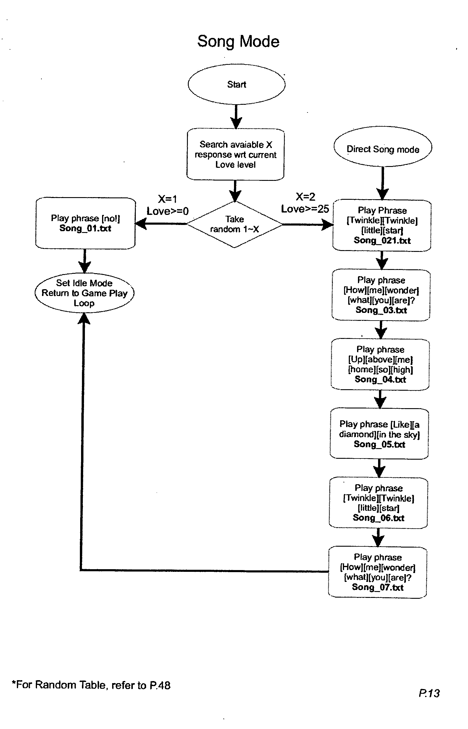


- While there have been illustrated and described particular embodiments of the present invention, it will be appreciated that numerous changes and modifications will occur to those skilled in the art, and it is intended in the appended claims to cover all those changes and modifications which fall within the true spirit and scope of the present invention.
Claims (29)
1. An electrically controlled animating apparatus for simulating life-like movements, the apparatus comprising:
a front facial area, a body and a plurality of movable body parts thereof;
sound generating circuitry for generating speech including multisyllabic words;
a plurality of sensors for detecting external inputs;
a controller responsive to the plurality of sensors;
said controller being operable to control the sound generating circuitry;
a mouth assembly on the front facial area comprising flexible molded material having upper and lower mouth portions and having first and second opposing corners thereof;
a first mouth mechanism operable with the mouth assembly for controlling the first and second-corners of the mouth assembly to define smile/emotion states of the mouth assembly responsive to external input from sensed conditions of the plurality of sensors;
a second mouth mechanism operable with the mouth assembly for controlling the upper and lower mouth portions to provide lip synchronism response to the multisyllabic words generated with the sound generating circuitry;
a drive system that powers movement of the first and second mouth mechanisms independently to simulate life-like responses to sensed conditions;
a first control shaft for the first mouth mechanism driven for rotation by the drive system;
a second control shaft for the second mouth mechanism driven by the drive system;
at least one of the first or second control shafts having a predetermined range of rotation for causing movement of at least one of the plurality of movable body parts in addition to the first or second mechanisms.
2. The animating apparatus as recited in claim 1 wherein said first control shaft causes movement of at least one of the plurality of movable body parts in addition to the first and second corners of the mouth assembly.
3. The animating apparatus as recited in claim 2 wherein said drive system further comprises a first reversible motor which powers the rotation of said first control shaft for movement of the corners of the mouth assembly, and a second reversible motor which powers the rotation of said second control shaft for movement of the upper and lower mouth portions of the mouth assembly.
4. The animating apparatus as recited in claim 3 further comprising a mechanical coupling between said second motor and said second control shaft for transmitting rotary output power from the second motor to the second shaft for rotation thereof.
5. The animating apparatus as recited in claim 4 wherein said at least one of the plurality of movable body parts includes a foot portion, and rotation of said second control shaft in a direction causes movement of said foot portion and rotation of said second control shaft in an opposite direction causes movement of said second mouth mechanism for controlling upper and lower mouth portions of said mouth assembly.
6. The animating apparatus as recited in claim 5 wherein said mechanical coupling comprises one or more of a shuttle gear or a clutch mechanism between said second motor and said second control shaft for transmitting rotary output power from the second motor to the second shaft for rotation of said second control shaft in the direction causing movement of said foot portion and rotation of said second control shaft in the opposite direction causing movement of said second mouth mechanism.
7. The animating apparatus as recited in claim 1 wherein said controller provides the animating apparatus with a plurality of states comprising animating apparatus modes that include excited, sleeping, and waking modes.
8. The animating apparatus as recited in claim 2 wherein said at least one of a plurality of body parts includes one or more of the following: an ear assembly; an eye assembly; an eye lid assembly; a plume assembly; a brow assembly; and a chest assembly.
9. The animating apparatus as recited in claim 2 wherein said first and second corners of the mouth assembly pivot to a neutral state an up/smile state and a down/frown state.
10. The animating apparatus as recited in claim 9 wherein said first control shaft has a neutral position in the predetermined range of shaft rotation with the corners of the mouth assembly in a neutral state.
11. An animating system comprising:
means for generating speech including multisyllabic words;
means for detecting external sensor inputs;
means for controlling the means for generating speech responsive to the means for detecting external sensor inputs;
said means for controlling being operable to control a mouth assembly comprising flexible molded material having upper and lower mouth portions and having first and second opposing corners thereof;
said means for controlling being operable to control a first mouth mechanism operable with the mouth assembly for controlling the first and second corners of the mouth assembly to define smile/emotion states of the mouth assembly responsive to external input from sensed conditions;
said means for controlling being operable to control a second mouth mechanism operable with the mouth assembly for controlling the upper and lower mouth portions to provide lip synchronism response to the multisyllabic words generated with the sound generating; and
means for driving movement of the first and second mouth mechanisms independently to simulate life-like responses to sensed conditions including a first control shaft for the first mouth mechanism driven for rotation by the drive system, and a second control shaft for the second mouth mechanism driven by the drive system with at least one of the first or second control shafts having a predetermined range of rotation for causing movement of at least one of the plurality of movable body parts in addition to the first or second mechanisms.
12. The animating system as recited in claim 11 wherein said first control shaft causes movement of at least one of the plurality of movable body parts in addition to the first and second corners of the mouth assembly.
13. The animating system as recited in claim 12 wherein said drive system further comprises a first reversible motor which powers the rotation of said first control shaft for movement of the corners of the mouth assembly, and a second reversible motor which powers the rotation of said second control shaft for movement of the upper and lower mouth portions of the mouth assembly.
14. The animating system as recited in claim 13 further comprising means for coupling between said second motor and said second control shaft for transmitting rotary output power from the second motor to the second shaft for rotation thereof.
15. The animating system as recited in claim 14 wherein said at least one of the plurality of movable body parts includes a foot portion, and rotation of said second control shaft in a direction causes movement of said foot portion and rotation of said second control shaft in an opposite direction causes movement of said second mouth mechanism for controlling upper and lower mouth portions of said mouth assembly.
16. An animating method comprising:
generating speech including multisyllabic words;
detecting external sensor inputs;
controlling a mouth assembly comprising flexible molded material having upper and lower mouth portions and having first and second opposing corners thereof for generating speech responsive thereto and detecting external sensor inputs;
controlling a first mouth mechanism operable with the mouth assembly for controlling the first and second corners of the mouth assembly to define smile/emotion states of the mouth assembly responsive to external input from sensed conditions;
controlling a second mouth mechanism operable with the mouth assembly for controlling the upper and lower mouth portions to provide lip synchronism response to the multisyllabic words generated with the sound generating; and
driving movement of the first and second mouth mechanisms independently to simulate life-like responses to sensed conditions including a first control shaft for the first mouth mechanism driven for rotation by the drive system, and a second control shaft for the second mouth mechanism driven by the drive system with at least one of the first or second control shafts having a predetermined range of rotation for causing movement of at least one of the plurality of movable body parts in addition to the first or second mechanisms.
17. The animating method as recited in claim 16 wherein said first control shaft causes movement of at least one of the plurality of movable body parts in addition to the first and second corners of the mouth assembly.
18. The animating method as recited in claim 16 wherein said controlling provides a plurality of states comprising modes that include excited, sleeping, and waking modes.
19. The animating method as recited in claim 18 wherein at least one of a plurality of body parts includes one or more of the following: an ear assembly; an eye assembly; an eye lid assembly; a plume assembly; a brow assembly; and a chest assembly.
20. The animating method as recited in claim 17 wherein said first and second corners of the mouth assembly pivot to a neutral state an up/smile state and a down/frown state, and said first control shaft has a neutral position in the predetermined range of shaft rotation with the corners of the mouth assembly in a neutral state.
21. An electrically controlled animating apparatus for simulating life-like movements, the apparatus comprising:
a front facial area of a character head and a plurality of movable parts thereof;
a mouth assembly on the front facial area comprising flexible molded material having upper and lower lips and having first and second opposing corners where the lips meet;
a first mouth mechanism operable with the mouth assembly for animating the first and second corners of the mouth assembly;
a second mouth mechanism operable with the mouth assembly for animating the upper and lower mouth portions for animating the lips between opened and closed positions independent of the first mouth mechanism;
a drive system that powers movement of the first and second mouth mechanisms independently to simulate life-like responses and for causing movement of at least one of the plurality of movable parts in addition to the first or second mouth mechanisms.
22. The animating apparatus as recited in claim 21 wherein said first and second corners of the first mouth mechanism are moveable between neutral, up/smile state and down/frown states.
23. The animating apparatus as recited in claim 21 wherein said drive system further comprises a first reversible motor which powers the movement of the corners of the mouth assembly, and a second reversible motor which powers the movement of the upper and lower mouth portions of the mouth assembly independently.
24. The animating apparatus as recited in claim 21 wherein the drive system facilitates the animating apparatus with a plurality of states comprising animating apparatus modes that include excited, sleeping, and waking modes.
25. The animating apparatus as recited in claim 24 wherein the plurality of modes includes movement of one or more of the following moveable parts: an ear assembly; an eye assembly; an eye lid assembly; a plume assembly; a brow assembly; and a chest assembly.
26. An electrically controlled animating apparatus for simulating life-like movements in a front facial area of a character head, the apparatus comprising:
a molded flexible elastomeric mouth including upper and lower lips having center portions and opposite side corners where the lips meet, the mouth including attachment points at the center portions and corners;
a first animation mechanism for animating the mouth for simulated talking movement by moving the attachment points at the center portions; and
a second animating mechanism independent from the first animating mechanism for moving the attachment points at the corners to simulate mouth movement corresponding to facial expression;
wherein the first and second animating mechanisms act to distort the elastomeric mouth to achieve simulated talking movement and facial expression as the animating mechanisms are operated.
27. The animating apparatus as recited in claim 26 comprising a drive system that powers movement of the first animation mechanism independent of the movement of the second animation mechanism for providing simulated talking movement or facial expression, or a combination thereof as the animating mechanisms are operated.
28. The animating apparatus as recited in claim 26 , said elastomeric mouth comprising a neutral undeformed position, wherein the second animating mechanism moves the attachment points at the corners to deform the elastomeric mouth from the neutral undeformed position.
29. The animating apparatus as recited in claim 28 wherein said opposite side corners where the lips meet are moveable between neutral, up/smile state and down/frown states with the second animating mechanism.
Priority Applications (2)
| Application Number | Priority Date | Filing Date | Title |
|---|---|---|---|
| US11/140,483 US20060270312A1 (en) | 2005-05-27 | 2005-05-27 | Interactive animated characters |
| PCT/US2006/013467 WO2006130240A2 (en) | 2005-05-27 | 2006-04-07 | Interactive animated characters |
Applications Claiming Priority (1)
| Application Number | Priority Date | Filing Date | Title |
|---|---|---|---|
| US11/140,483 US20060270312A1 (en) | 2005-05-27 | 2005-05-27 | Interactive animated characters |
Publications (1)
| Publication Number | Publication Date |
|---|---|
| US20060270312A1 true US20060270312A1 (en) | 2006-11-30 |
Family
ID=37464067
Family Applications (1)
| Application Number | Title | Priority Date | Filing Date |
|---|---|---|---|
| US11/140,483 Abandoned US20060270312A1 (en) | 2005-05-27 | 2005-05-27 | Interactive animated characters |
Country Status (2)
| Country | Link |
|---|---|
| US (1) | US20060270312A1 (en) |
| WO (1) | WO2006130240A2 (en) |
Cited By (16)
| Publication number | Priority date | Publication date | Assignee | Title |
|---|---|---|---|---|
| US20070128979A1 (en) * | 2005-12-07 | 2007-06-07 | J. Shackelford Associates Llc. | Interactive Hi-Tech doll |
| GB2451082A (en) * | 2007-07-17 | 2009-01-21 | Triple One Co Ltd | Microprocessor controlled interactive toy with motor movement detecting means and voicing means. |
| US20090181598A1 (en) * | 2008-01-14 | 2009-07-16 | Mattel, Inc. | Method and Apparatus for Performing Try-Me and Normal Play Routines |
| US20110295513A1 (en) * | 2010-05-25 | 2011-12-01 | Shigeru Owada | Information processing apparatus, information output method, and program |
| US8353767B1 (en) * | 2007-07-13 | 2013-01-15 | Ganz | System and method for a virtual character in a virtual world to interact with a user |
| US20130178982A1 (en) * | 2012-01-06 | 2013-07-11 | Tit Shing Wong | Interactive personal robotic apparatus |
| ITTO20120169A1 (en) * | 2012-02-24 | 2013-08-25 | Fabio Caposio | ANIMATION DEVICE FOR A JEWELRY, RANGER OR THE LIKE |
| US8662955B1 (en) | 2009-10-09 | 2014-03-04 | Mattel, Inc. | Toy figures having multiple cam-actuated moving parts |
| US20160193536A1 (en) * | 2015-01-02 | 2016-07-07 | Imc Toys, S.A. | Mechanical eye for a toy |
| US9474981B1 (en) * | 2015-11-06 | 2016-10-25 | William Mark Corporation | Manually actuated plush toy with mood change |
| US9586156B2 (en) | 2013-07-02 | 2017-03-07 | Hasbro, Inc. | Bidirectional gear assembly for electromechanical toys |
| US20180158458A1 (en) * | 2016-10-21 | 2018-06-07 | Shenetics, Inc. | Conversational voice interface of connected devices, including toys, cars, avionics, mobile, iot and home appliances |
| US20200246982A1 (en) * | 2017-10-31 | 2020-08-06 | Sony Corporation | Robot device |
| US11071923B2 (en) * | 2017-05-30 | 2021-07-27 | Whatsitsface, Llc | Toy with multiple face expressions |
| US11103800B1 (en) | 2017-02-17 | 2021-08-31 | Hasbro, Inc. | Toy robot with programmable and movable appendages |
| CN117124343A (en) * | 2023-09-25 | 2023-11-28 | 深圳无芯科技有限公司 | Head and neck structure of bionic robot and bionic robot |
Citations (42)
| Publication number | Priority date | Publication date | Assignee | Title |
|---|---|---|---|---|
| US2250916A (en) * | 1938-02-28 | 1941-07-29 | Automatic Instr Company | Robot lip action |
| US3477169A (en) * | 1967-12-06 | 1969-11-11 | Lettam Inc | Doll sound producing mechanism with head movement |
| US3841020A (en) * | 1966-04-22 | 1974-10-15 | Mattel Inc | Facial animating means for a figure toy |
| US4177589A (en) * | 1977-10-11 | 1979-12-11 | Walt Disney Productions | Three-dimensional animated facial control |
| US4294033A (en) * | 1979-02-09 | 1981-10-13 | Marvin Glass & Associates | Animated talking doll |
| US4683669A (en) * | 1983-04-28 | 1987-08-04 | Greer Jr Thomas J | Motor element for facially animated mannequin |
| US4696653A (en) * | 1986-02-07 | 1987-09-29 | Worlds Of Wonder, Inc. | Speaking toy doll |
| US4775352A (en) * | 1986-02-07 | 1988-10-04 | Lawrence T. Jones | Talking doll with animated features |
| US4808142A (en) * | 1987-02-06 | 1989-02-28 | Coleco Industries, Inc. | Doll with controlled mouth actuation in simulated speech |
| US4850930A (en) * | 1986-02-10 | 1989-07-25 | Tomy Kogyo Co., Inc. | Animated toy |
| US4900289A (en) * | 1988-01-29 | 1990-02-13 | Cal R&D, Inc. | Mechanism for animating a doll's facial features |
| US5021878A (en) * | 1989-09-20 | 1991-06-04 | Semborg-Recrob, Corp. | Animated character system with real-time control |
| US5074821A (en) * | 1990-01-18 | 1991-12-24 | Worlds Of Wonder, Inc. | Character animation method and apparatus |
| US5141464A (en) * | 1991-01-23 | 1992-08-25 | Mattel, Inc. | Touch responsive animated toy figure |
| US5142803A (en) * | 1989-09-20 | 1992-09-01 | Semborg-Recrob, Corp. | Animated character system with real-time contol |
| US5281143A (en) * | 1992-05-08 | 1994-01-25 | Toy Biz, Inc. | Learning doll |
| US5314336A (en) * | 1992-02-07 | 1994-05-24 | Mark Diamond | Toy and method providing audio output representative of message optically sensed by the toy |
| US5324225A (en) * | 1990-12-11 | 1994-06-28 | Takara Co., Ltd. | Interactive toy figure with sound-activated and pressure-activated switches |
| US5376038A (en) * | 1994-01-18 | 1994-12-27 | Toy Biz, Inc. | Doll with programmable speech activated by pressure on particular parts of head and body |
| US5399115A (en) * | 1992-08-04 | 1995-03-21 | Toy Biz, Inc. | Blinking doll with power storage mechanism |
| US5407376A (en) * | 1993-01-31 | 1995-04-18 | Avital; Noni | Voice-responsive doll eye mechanism |
| US5413516A (en) * | 1993-12-20 | 1995-05-09 | Fung Seng Industrial Co., Ltd. | Talking toy doll |
| US5413518A (en) * | 1994-01-18 | 1995-05-09 | Lin; Ming-Tuan | Proximity responsive toy |
| US5415579A (en) * | 1991-04-24 | 1995-05-16 | Concepts Development Australia Pty Ltd | Doll with pivoting eyeballs, heart beat, voice means, burping sounds and actuating transmitter |
| US5746602A (en) * | 1996-02-27 | 1998-05-05 | Kikinis; Dan | PC peripheral interactive doll |
| US5800242A (en) * | 1996-12-23 | 1998-09-01 | Prema Toy Company, Inc. | Reinforced articles of elastomeric material |
| US5820441A (en) * | 1994-10-27 | 1998-10-13 | Inntoy Pty. Ltd. | Animated doll |
| US5820440A (en) * | 1996-09-06 | 1998-10-13 | Pragmatic Designs, Inc. | Toy figure with rump-actuated sound generator |
| US5823847A (en) * | 1997-02-18 | 1998-10-20 | Pragmatic Designs, Inc. | Moving mouth mechanism for animated characters |
| US5832189A (en) * | 1996-09-26 | 1998-11-03 | Interval Research Corporation | Affect-based robot communication methods and systems |
| US5870842A (en) * | 1996-05-02 | 1999-02-16 | Disney Enterprises, Inc. | Apparatus for controlling an animated figure |
| US5989092A (en) * | 1996-08-02 | 1999-11-23 | Trendmasters Inc. | Interactive toy |
| US5989091A (en) * | 1995-07-28 | 1999-11-23 | Rodgers; Nicholas A. | Bathtub toy |
| US6017261A (en) * | 1998-08-21 | 2000-01-25 | Telco Creations, Inc. | Animated mechanized figure |
| US6149490A (en) * | 1998-12-15 | 2000-11-21 | Tiger Electronics, Ltd. | Interactive toy |
| US6160986A (en) * | 1998-04-16 | 2000-12-12 | Creator Ltd | Interactive toy |
| US6503123B2 (en) * | 1999-12-30 | 2003-01-07 | Toyinnovation Inc | Toys incorporating geneva gear assemblies |
| US6672934B2 (en) * | 2000-02-04 | 2004-01-06 | Trendmasters, Inc. | Amusement device |
| US6971943B1 (en) * | 2003-09-30 | 2005-12-06 | Arne Schulze | Interactive sound producing toy |
| US20050287913A1 (en) * | 2004-06-02 | 2005-12-29 | Steven Ellman | Expression mechanism for a toy, such as a doll, having fixed or movable eyes |
| US7021988B2 (en) * | 2002-05-17 | 2006-04-04 | Thin Air Creations, Llc | Expressive feature mechanism for animated characters and devices |
| US20060094326A1 (en) * | 2004-11-01 | 2006-05-04 | Kiu Hung Industries Ltd. | Electromotive toy processor with voice synchronisation |
-
2005
- 2005-05-27 US US11/140,483 patent/US20060270312A1/en not_active Abandoned
-
2006
- 2006-04-07 WO PCT/US2006/013467 patent/WO2006130240A2/en active Application Filing
Patent Citations (46)
| Publication number | Priority date | Publication date | Assignee | Title |
|---|---|---|---|---|
| US2250916A (en) * | 1938-02-28 | 1941-07-29 | Automatic Instr Company | Robot lip action |
| US3841020A (en) * | 1966-04-22 | 1974-10-15 | Mattel Inc | Facial animating means for a figure toy |
| US3477169A (en) * | 1967-12-06 | 1969-11-11 | Lettam Inc | Doll sound producing mechanism with head movement |
| US4177589A (en) * | 1977-10-11 | 1979-12-11 | Walt Disney Productions | Three-dimensional animated facial control |
| US4294033A (en) * | 1979-02-09 | 1981-10-13 | Marvin Glass & Associates | Animated talking doll |
| US4683669A (en) * | 1983-04-28 | 1987-08-04 | Greer Jr Thomas J | Motor element for facially animated mannequin |
| US4696653A (en) * | 1986-02-07 | 1987-09-29 | Worlds Of Wonder, Inc. | Speaking toy doll |
| US4775352A (en) * | 1986-02-07 | 1988-10-04 | Lawrence T. Jones | Talking doll with animated features |
| US4850930A (en) * | 1986-02-10 | 1989-07-25 | Tomy Kogyo Co., Inc. | Animated toy |
| US4808142A (en) * | 1987-02-06 | 1989-02-28 | Coleco Industries, Inc. | Doll with controlled mouth actuation in simulated speech |
| US4900289A (en) * | 1988-01-29 | 1990-02-13 | Cal R&D, Inc. | Mechanism for animating a doll's facial features |
| US5021878A (en) * | 1989-09-20 | 1991-06-04 | Semborg-Recrob, Corp. | Animated character system with real-time control |
| US5142803A (en) * | 1989-09-20 | 1992-09-01 | Semborg-Recrob, Corp. | Animated character system with real-time contol |
| US5074821A (en) * | 1990-01-18 | 1991-12-24 | Worlds Of Wonder, Inc. | Character animation method and apparatus |
| US5324225A (en) * | 1990-12-11 | 1994-06-28 | Takara Co., Ltd. | Interactive toy figure with sound-activated and pressure-activated switches |
| US5141464A (en) * | 1991-01-23 | 1992-08-25 | Mattel, Inc. | Touch responsive animated toy figure |
| US5415579A (en) * | 1991-04-24 | 1995-05-16 | Concepts Development Australia Pty Ltd | Doll with pivoting eyeballs, heart beat, voice means, burping sounds and actuating transmitter |
| US5314336A (en) * | 1992-02-07 | 1994-05-24 | Mark Diamond | Toy and method providing audio output representative of message optically sensed by the toy |
| US5281143A (en) * | 1992-05-08 | 1994-01-25 | Toy Biz, Inc. | Learning doll |
| US5399115A (en) * | 1992-08-04 | 1995-03-21 | Toy Biz, Inc. | Blinking doll with power storage mechanism |
| US5407376A (en) * | 1993-01-31 | 1995-04-18 | Avital; Noni | Voice-responsive doll eye mechanism |
| US5413516A (en) * | 1993-12-20 | 1995-05-09 | Fung Seng Industrial Co., Ltd. | Talking toy doll |
| US5413518A (en) * | 1994-01-18 | 1995-05-09 | Lin; Ming-Tuan | Proximity responsive toy |
| US5376038A (en) * | 1994-01-18 | 1994-12-27 | Toy Biz, Inc. | Doll with programmable speech activated by pressure on particular parts of head and body |
| US5820441A (en) * | 1994-10-27 | 1998-10-13 | Inntoy Pty. Ltd. | Animated doll |
| US5989091A (en) * | 1995-07-28 | 1999-11-23 | Rodgers; Nicholas A. | Bathtub toy |
| US5746602A (en) * | 1996-02-27 | 1998-05-05 | Kikinis; Dan | PC peripheral interactive doll |
| US5870842A (en) * | 1996-05-02 | 1999-02-16 | Disney Enterprises, Inc. | Apparatus for controlling an animated figure |
| US5989092A (en) * | 1996-08-02 | 1999-11-23 | Trendmasters Inc. | Interactive toy |
| US5820440A (en) * | 1996-09-06 | 1998-10-13 | Pragmatic Designs, Inc. | Toy figure with rump-actuated sound generator |
| US5832189A (en) * | 1996-09-26 | 1998-11-03 | Interval Research Corporation | Affect-based robot communication methods and systems |
| US5800242A (en) * | 1996-12-23 | 1998-09-01 | Prema Toy Company, Inc. | Reinforced articles of elastomeric material |
| US5823847A (en) * | 1997-02-18 | 1998-10-20 | Pragmatic Designs, Inc. | Moving mouth mechanism for animated characters |
| US6160986A (en) * | 1998-04-16 | 2000-12-12 | Creator Ltd | Interactive toy |
| US6017261A (en) * | 1998-08-21 | 2000-01-25 | Telco Creations, Inc. | Animated mechanized figure |
| US6149490A (en) * | 1998-12-15 | 2000-11-21 | Tiger Electronics, Ltd. | Interactive toy |
| US6497607B1 (en) * | 1998-12-15 | 2002-12-24 | Hasbro, Inc. | Interactive toy |
| US6514117B1 (en) * | 1998-12-15 | 2003-02-04 | David Mark Hampton | Interactive toy |
| US6537128B1 (en) * | 1998-12-15 | 2003-03-25 | Hasbro, Inc. | Interactive toy |
| US6544098B1 (en) * | 1998-12-15 | 2003-04-08 | Hasbro, Inc. | Interactive toy |
| US6503123B2 (en) * | 1999-12-30 | 2003-01-07 | Toyinnovation Inc | Toys incorporating geneva gear assemblies |
| US6672934B2 (en) * | 2000-02-04 | 2004-01-06 | Trendmasters, Inc. | Amusement device |
| US7021988B2 (en) * | 2002-05-17 | 2006-04-04 | Thin Air Creations, Llc | Expressive feature mechanism for animated characters and devices |
| US6971943B1 (en) * | 2003-09-30 | 2005-12-06 | Arne Schulze | Interactive sound producing toy |
| US20050287913A1 (en) * | 2004-06-02 | 2005-12-29 | Steven Ellman | Expression mechanism for a toy, such as a doll, having fixed or movable eyes |
| US20060094326A1 (en) * | 2004-11-01 | 2006-05-04 | Kiu Hung Industries Ltd. | Electromotive toy processor with voice synchronisation |
Cited By (20)
| Publication number | Priority date | Publication date | Assignee | Title |
|---|---|---|---|---|
| US20070128979A1 (en) * | 2005-12-07 | 2007-06-07 | J. Shackelford Associates Llc. | Interactive Hi-Tech doll |
| US8353767B1 (en) * | 2007-07-13 | 2013-01-15 | Ganz | System and method for a virtual character in a virtual world to interact with a user |
| GB2451082A (en) * | 2007-07-17 | 2009-01-21 | Triple One Co Ltd | Microprocessor controlled interactive toy with motor movement detecting means and voicing means. |
| US20090181598A1 (en) * | 2008-01-14 | 2009-07-16 | Mattel, Inc. | Method and Apparatus for Performing Try-Me and Normal Play Routines |
| US8371896B2 (en) * | 2008-01-14 | 2013-02-12 | Mattel, Inc. | Method and apparatus for performing try-me and normal play routines |
| US8662955B1 (en) | 2009-10-09 | 2014-03-04 | Mattel, Inc. | Toy figures having multiple cam-actuated moving parts |
| US20110295513A1 (en) * | 2010-05-25 | 2011-12-01 | Shigeru Owada | Information processing apparatus, information output method, and program |
| US20130178982A1 (en) * | 2012-01-06 | 2013-07-11 | Tit Shing Wong | Interactive personal robotic apparatus |
| US9079113B2 (en) * | 2012-01-06 | 2015-07-14 | J. T. Labs Limited | Interactive personal robotic apparatus |
| ITTO20120169A1 (en) * | 2012-02-24 | 2013-08-25 | Fabio Caposio | ANIMATION DEVICE FOR A JEWELRY, RANGER OR THE LIKE |
| US10179294B2 (en) | 2013-07-02 | 2019-01-15 | Hasbro, Inc. | Bidirectional gear assembly for electromechanical toys |
| US9586156B2 (en) | 2013-07-02 | 2017-03-07 | Hasbro, Inc. | Bidirectional gear assembly for electromechanical toys |
| US20160193536A1 (en) * | 2015-01-02 | 2016-07-07 | Imc Toys, S.A. | Mechanical eye for a toy |
| US9474981B1 (en) * | 2015-11-06 | 2016-10-25 | William Mark Corporation | Manually actuated plush toy with mood change |
| WO2017078943A3 (en) * | 2015-11-06 | 2017-06-15 | William Mark Corporation | Manually actuated plush toy with mood change |
| US20180158458A1 (en) * | 2016-10-21 | 2018-06-07 | Shenetics, Inc. | Conversational voice interface of connected devices, including toys, cars, avionics, mobile, iot and home appliances |
| US11103800B1 (en) | 2017-02-17 | 2021-08-31 | Hasbro, Inc. | Toy robot with programmable and movable appendages |
| US11071923B2 (en) * | 2017-05-30 | 2021-07-27 | Whatsitsface, Llc | Toy with multiple face expressions |
| US20200246982A1 (en) * | 2017-10-31 | 2020-08-06 | Sony Corporation | Robot device |
| CN117124343A (en) * | 2023-09-25 | 2023-11-28 | 深圳无芯科技有限公司 | Head and neck structure of bionic robot and bionic robot |
Also Published As
| Publication number | Publication date |
|---|---|
| WO2006130240A2 (en) | 2006-12-07 |
| WO2006130240A3 (en) | 2007-12-06 |
Similar Documents
| Publication | Publication Date | Title |
|---|---|---|
| US20060270312A1 (en) | Interactive animated characters | |
| US6544098B1 (en) | Interactive toy | |
| US7507139B1 (en) | Electromechanical toy | |
| US6558225B1 (en) | Electronic figurines | |
| US5407376A (en) | Voice-responsive doll eye mechanism | |
| US7322874B2 (en) | Expression mechanism for a toy, such as a doll, having fixed or moveable eyes | |
| EP2051787B1 (en) | Dolls with alterable facial features | |
| US20020055320A1 (en) | Motion expressible toy | |
| JPS62194882A (en) | Sound emitting living doll | |
| US20080026669A1 (en) | Interactive response system for a figure | |
| JPS59101180A (en) | Animal action toy | |
| US20050233675A1 (en) | Animated multi-persona toy | |
| US9878261B1 (en) | Toy reactive to a signal | |
| US20070178804A1 (en) | Toy vehicle having fanciful facial expression | |
| US7942720B1 (en) | Animated “peek-a-boo” stuffed toy creature | |
| US7695341B1 (en) | Electromechanical toy | |
| US7207859B1 (en) | Realistic animatronic toy | |
| US20190118105A1 (en) | Interactive robotic toy | |
| US20070184750A1 (en) | Doll and face-licking puppy combination | |
| CA3003530A1 (en) | Interactive robotic toy | |
| JP2009011504A (en) | Ornament toy | |
| US20010053651A1 (en) | Talking numbers doll | |
| JPH0265887A (en) | Working toy | |
| US20230301241A1 (en) | System and method for animating a plant | |
| JP2019170544A (en) | Action device, action toy and system |
Legal Events
| Date | Code | Title | Description |
|---|---|---|---|
| AS | Assignment |
Owner name: HASBRO, INC., RHODE ISLAND Free format text: ASSIGNMENT OF ASSIGNORS INTEREST;ASSIGNORS:MADDOCKS, RICHARD C.;RODRIGUEZ, EDUARDO J.;FORD, JEFFREY M.;AND OTHERS;REEL/FRAME:016920/0821;SIGNING DATES FROM 20050720 TO 20050812 |
|
| STCB | Information on status: application discontinuation |
Free format text: ABANDONED -- FAILURE TO RESPOND TO AN OFFICE ACTION |