US20060086249A1 - Membrane-based reservoir dryer - Google Patents
Membrane-based reservoir dryer Download PDFInfo
- Publication number
- US20060086249A1 US20060086249A1 US11/257,256 US25725605A US2006086249A1 US 20060086249 A1 US20060086249 A1 US 20060086249A1 US 25725605 A US25725605 A US 25725605A US 2006086249 A1 US2006086249 A1 US 2006086249A1
- Authority
- US
- United States
- Prior art keywords
- reservoir
- fluid
- fluid reservoir
- moisture
- gas
- Prior art date
- Legal status (The legal status is an assumption and is not a legal conclusion. Google has not performed a legal analysis and makes no representation as to the accuracy of the status listed.)
- Granted
Links
- 239000012528 membrane Substances 0.000 title claims abstract description 50
- 239000012530 fluid Substances 0.000 claims abstract description 142
- 239000000356 contaminant Substances 0.000 claims abstract description 27
- 238000000034 method Methods 0.000 claims abstract description 10
- 238000004891 communication Methods 0.000 claims abstract description 4
- 238000001035 drying Methods 0.000 claims abstract description 4
- 239000002274 desiccant Substances 0.000 claims description 38
- 239000000443 aerosol Substances 0.000 claims description 9
- 239000012080 ambient air Substances 0.000 claims description 7
- 238000002347 injection Methods 0.000 claims description 5
- 239000007924 injection Substances 0.000 claims description 5
- 238000012354 overpressurization Methods 0.000 claims description 3
- 230000003750 conditioning effect Effects 0.000 claims description 2
- 239000003570 air Substances 0.000 description 19
- XLYOFNOQVPJJNP-UHFFFAOYSA-N water Substances O XLYOFNOQVPJJNP-UHFFFAOYSA-N 0.000 description 10
- 230000001276 controlling effect Effects 0.000 description 6
- 239000007788 liquid Substances 0.000 description 5
- 230000001050 lubricating effect Effects 0.000 description 4
- 238000013459 approach Methods 0.000 description 3
- 238000011109 contamination Methods 0.000 description 3
- 239000000463 material Substances 0.000 description 3
- 238000005516 engineering process Methods 0.000 description 2
- 238000001914 filtration Methods 0.000 description 2
- 238000004519 manufacturing process Methods 0.000 description 2
- 239000003208 petroleum Substances 0.000 description 2
- 238000009825 accumulation Methods 0.000 description 1
- 238000009833 condensation Methods 0.000 description 1
- 230000005494 condensation Effects 0.000 description 1
- 238000001816 cooling Methods 0.000 description 1
- 230000002596 correlated effect Effects 0.000 description 1
- 125000004122 cyclic group Chemical group 0.000 description 1
- 230000003247 decreasing effect Effects 0.000 description 1
- 238000011161 development Methods 0.000 description 1
- 230000009977 dual effect Effects 0.000 description 1
- 230000003203 everyday effect Effects 0.000 description 1
- 239000006260 foam Substances 0.000 description 1
- 239000000314 lubricant Substances 0.000 description 1
- 238000005461 lubrication Methods 0.000 description 1
- 238000012544 monitoring process Methods 0.000 description 1
- 239000002245 particle Substances 0.000 description 1
- 238000011160 research Methods 0.000 description 1
- 230000029058 respiratory gaseous exchange Effects 0.000 description 1
- 229920006395 saturated elastomer Polymers 0.000 description 1
- 238000007789 sealing Methods 0.000 description 1
- 230000011664 signaling Effects 0.000 description 1
Images


Classifications
-
- F—MECHANICAL ENGINEERING; LIGHTING; HEATING; WEAPONS; BLASTING
- F15—FLUID-PRESSURE ACTUATORS; HYDRAULICS OR PNEUMATICS IN GENERAL
- F15B—SYSTEMS ACTING BY MEANS OF FLUIDS IN GENERAL; FLUID-PRESSURE ACTUATORS, e.g. SERVOMOTORS; DETAILS OF FLUID-PRESSURE SYSTEMS, NOT OTHERWISE PROVIDED FOR
- F15B1/00—Installations or systems with accumulators; Supply reservoir or sump assemblies
- F15B1/26—Supply reservoir or sump assemblies
-
- B—PERFORMING OPERATIONS; TRANSPORTING
- B01—PHYSICAL OR CHEMICAL PROCESSES OR APPARATUS IN GENERAL
- B01D—SEPARATION
- B01D53/00—Separation of gases or vapours; Recovering vapours of volatile solvents from gases; Chemical or biological purification of waste gases, e.g. engine exhaust gases, smoke, fumes, flue gases, aerosols
- B01D53/22—Separation of gases or vapours; Recovering vapours of volatile solvents from gases; Chemical or biological purification of waste gases, e.g. engine exhaust gases, smoke, fumes, flue gases, aerosols by diffusion
-
- B—PERFORMING OPERATIONS; TRANSPORTING
- B01—PHYSICAL OR CHEMICAL PROCESSES OR APPARATUS IN GENERAL
- B01D—SEPARATION
- B01D53/00—Separation of gases or vapours; Recovering vapours of volatile solvents from gases; Chemical or biological purification of waste gases, e.g. engine exhaust gases, smoke, fumes, flue gases, aerosols
- B01D53/26—Drying gases or vapours
- B01D53/261—Drying gases or vapours by adsorption
-
- B—PERFORMING OPERATIONS; TRANSPORTING
- B01—PHYSICAL OR CHEMICAL PROCESSES OR APPARATUS IN GENERAL
- B01D—SEPARATION
- B01D53/00—Separation of gases or vapours; Recovering vapours of volatile solvents from gases; Chemical or biological purification of waste gases, e.g. engine exhaust gases, smoke, fumes, flue gases, aerosols
- B01D53/26—Drying gases or vapours
- B01D53/268—Drying gases or vapours by diffusion
-
- F—MECHANICAL ENGINEERING; LIGHTING; HEATING; WEAPONS; BLASTING
- F15—FLUID-PRESSURE ACTUATORS; HYDRAULICS OR PNEUMATICS IN GENERAL
- F15B—SYSTEMS ACTING BY MEANS OF FLUIDS IN GENERAL; FLUID-PRESSURE ACTUATORS, e.g. SERVOMOTORS; DETAILS OF FLUID-PRESSURE SYSTEMS, NOT OTHERWISE PROVIDED FOR
- F15B21/00—Common features of fluid actuator systems; Fluid-pressure actuator systems or details thereof, not covered by any other group of this subclass
- F15B21/04—Special measures taken in connection with the properties of the fluid
- F15B21/041—Removal or measurement of solid or liquid contamination, e.g. filtering
Definitions
- This invention relates to lubricating and hydraulic systems, and more specifically to a method and device for preventing ingression of contaminants and moisture and for removing moisture from a fluid reservoir of lubricating and hydraulic systems.
- Lubricating and hydraulic fluids are used extensively throughout manufacturing plants and in industrial machinery. In most of these applications, the fluid is contained in a reservoir and is delivered to the desired locations by either the action of a pump or by splash-lubrication. When the fluid is pumped to the desired location, atmospheric air is drawn into the reservoir to take up the volume of the pumped out oil and thus prevent any amount of vacuum in the reservoir, as the typical reservoir is not designed for vacuum service. Additionally in equipment that may not run continuously, atmospheric air may be drawn into a reservoir due to volume changes upon cooling. This exchange of air between the reservoir and the ambient surroundings is known in the art as reservoir breathing.
- the simplest approach used in the art is a turn down pipe 11 , as shown in the reservoir 10 FIG. 1 .
- the turn down pipe 11 basically prevents the gross ingression of liquid water when the reservoir 10 gets wet with water either from a rainstorm in exterior applications, or a washdown in interior applications.
- a limitation in using the turn down pipe 11 is that the turn down pipe 11 does not prevent the ingression of particulates or atmospheric moisture.
- Filter media 15 used in this type of filter varies widely from coarse open celled foam to fibrous filter media rated at 3-micron filtration. This approach is generally limited by pressure drop and efficiency of the filter and does nothing to prevent atmospheric moisture from entering the reservoir 12 . Additionally, in order for all the air entering the reservoir 12 to get filtered, the reservoir 12 must be completely sealed except for the breathers. Otherwise as the filter element increases in pressure drop due to the accumulation of particulates, the likelihood of particulate laden air entering the reservoir through any gaps in the sealing surfaces increases significantly.
- Desiccant breathers are also another type of technology used to address the issue of ingression of contaminants, as described in U.S. Pat. Nos. 4,504,289, 4,548,624, and 6,217,639 and illustrated in FIG. 3 .
- the desiccant breather 17 of FIG. 3 is shown as comprising a desiccant material 20 to absorb moisture and a filter media 19 to remove particulate.
- Desiccant breathers however are limited in that they have only a finite capacity for moisture removal and thus when the desiccant is spent, do not remove any additional moisture. Users thus are required to closely monitor the conditions of the desiccant and change-out the breathers on a frequent basis.
- desiccant breathers such as desiccant breather 17 , remove moisture only when the moisture is in close proximity of the desiccant material.
- desiccant breather 17 remove moisture only when the moisture is in close proximity of the desiccant material.
- the moisture must diffuse from the fluid surface to the desiccant material 17 . As these distances are often on the order of 1 to 10 feet, the process is very slow and essentially passive.
- a method and device for preventing ingression of contaminants and moisture and for removing moisture from a fluid supported in a fluid reservoir includes a fluid reservoir opening for allowing an exchanging of air between an interior of the fluid reservoir and the ambient surrounding air and a membrane-based reservoir dryer located in fluid communication with the fluid reservoir in one embodiment.
- the membrane-based reservoir dryer comprises a source of compressed gas, a filter and a coalescer for removing particulates and aerosol contaminants from the compressed gas, a membrane dryer for drying the compressed gas to increase the compressed gas's capacity for absorbing moisture from the fluid in the reservoir, and a means for controlling the flow of gas out of the membrane-based reservoir dryer.
- U.S. Pat. No. 4,504,289 teaches a breather cap for use on a liquid petroleum tank
- U.S. Pat. No. 4,504,289 teaches also a breather cap for use on a liquid petroleum tank
- U.S. Pat. No. 6,217,639 teaches a contamination control breather for use in conjunction with air inflow and outflow to and from machinery;
- U.S. Pat. No. 6,585,808 teaches a membrane module for use in the removal of water from compressed gas streams and a method of making the apparatus.
- FIG. 1 shows a cut-a-way view of a fluid reservoir having a turn down pipe for preventing the gross ingression of liquid water therein;
- FIG. 2 shows a cut-a-way view of a fluid reservoir having a filter breather for capturing airborne particulates to prevent the airborne particulates from entering into the fluid reservoir;
- FIG. 3 shows a cut-a-way view of a fluid reservoir having a desiccant breather to absorb moisture and a filter media to remove particulates;
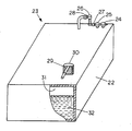
- FIG. 4 shows a cut-a-way view of an embodiment of the present invention comprising a fluid reservoir having a membrane-based reservoir dryer;
- FIG. 5 shows a cut-a-way view of a fluid reservoir having a membrane-based reservoir dryer in combination with a desiccant breather
- FIG. 6 shows a cut-a-way view of a fluid reservoir having a membrane-based reservoir dryer in combination with a control circuit
- FIG. 7 shows a cut-a-way view of a fluid reservoir having a membrane-based reservoir dryer in combination with a fluid level sensing means.
- FIG. 4 shows a fluid reservoir 22 having a membrane-based reservoir dryer 23 , which has the dual function of not only preventing the ingression of particulate and moisture into the fluid reservoir 22 but also removing moisture from a fluid 32 contained in the fluid reservoir 22 .
- the membrane-based reservoir dryer 23 comprises a source of compressed air or gas (not shown), a filter 24 and coalescer 25 , a membrane air dryer 26 , and an apparatus for controlling or metering the amount of flow out of the membrane air dryer, such as an orifice or a metering valve 27 .
- the membrane-based reservoir dryer 23 can also include a relief valve 28 for protecting against over pressurization of the reservoir 22 .
- the membrane-based reservoir dryer 23 can also include a particulate filter 29 located on the exit point of the reservoir 22 to provide further protection against the ingression of particulate.
- the embodiment of FIG. 4 shows the exit point of the reservoir 22 as comprising a breather 30 .
- the filter 24 and coalescer 25 of the membrane-based reservoir dryer 23 functions to remove particulates and aerosol contaminants from a compressed gas stream.
- the aerosol present in the compressed gas stream may be either a compressor lubricant or water droplets formed from condensation of the water saturated gas stream.
- the filter 24 and coalescer 25 preferably remove particles down below 1 micron in size.
- the membrane dryer 26 functions to dry the compressed gas sufficiently so that it has greater capacity for absorbing moisture from the fluid 32 in the reservoir 22 .
- One of the many suitable membrane dryers is described in U.S. Pat. No. 6,585,808.
- a metered amount of the gas is then injected into the reservoir 22 .
- the metering device may be a valve, orifice or any other means to control the desired amount of dry gas flow into the reservoir.
- the injection point for the dry gas is preferably located distal to the exit point for the gas and more preferably at one end of a reservoir 22 with the exit point for the gas located at the other end of the reservoir 22 , although other locations are suitable as well.
- the dry gas flows through a headspace 31 of the reservoir 22 maintaining a slight positive pressure relative to the ambient pressure of the environment surrounding the reservoir 22 . In this manner, contaminants in the form of particulate and ambient moisture cannot enter the reservoir 22 through the breather 30 because the contaminants would have to travel against a pressure gradient. In addition, as the dry gas flows across the surface of the fluid 32 , moisture will be removed from the fluid 32 in the reservoir 22 , provided the relative humidity of the dry gas is below the relative water saturation of the fluid 32 .
- the dry gas can be injected into the return pipe (not shown) that brings the fluid 32 back from the equipment to the reservoir 22 or the dry gas can be injected below the fluid surface, allowing for the gas to bubble up through the fluid 32 aiding in the stripping of moisture or other contaminants from the fluid 32 .
- FIG. 5 shows an alternative embodiment of the present invention comprising fluid reservoir 22 having membrane-based reservoir dryer 23 in combination with a desiccant breather 33 .
- Desiccant breather 33 is shown in FIG. 5 as comprising a breather for allowing an exchanging of air between an interior of the fluid reservoir 22 and the ambient surrounding, a desiccant media 35 for removing moisture from the air and a filter 36 for removing particulates from the air.
- the membrane-based reservoir dryer 23 is used to blanket the headspace 31 of the reservoir 22 with a dry gas and the gas that exits the reservoir 22 passes through the desiccant breather 33 .
- This aspect of the invention applies to reservoirs on equipments that are used intermittently, such as mobile equipment or plant equipment that shuts down every day.
- the compressed gas may only be available to the membrane-based reservoir dryer 23 when the equipment is operational.
- the membrane-based reservoir dryer 23 will only be protecting the reservoir 22 when the equipment is operational.
- the reservoir breather 33 is fitted with the desiccant media 34 .
- any atmospheric air that is drawn into the reservoir will pass through the desiccant media 35 which will remove the moisture from the air and the filter, which will remove the particulates from the air.
- a desiccant breather has a finite life when it has adsorbed all the moisture that the desiccant media can hold, but in the present invention the desiccant media 35 will be regenerated when the equipment and membrane-based reservoir dryer 23 is operational again because dry gas from the membrane-based reservoir dryer 23 will pass through the desiccant media as it is exhausted to the atmosphere, striping away any adsorbed moisture, thus overcoming the need for frequent replacement of the desiccant breathers 33
- Another application of the membrane-based reservoir dryer 23 in combination with a desiccant breather 33 of FIG. 5 is for reservoirs that experience a cyclic variation of the fluid level, such as but not limited to hydraulic reservoirs that are part of a system that includes hydraulic rams.
- a large volume of fluid may be rapidly pumped into the ram thus lowering the fluid volume in the reservoir as work is being done by the hydraulic ram. Fluid then returns to the reservoir when the hydraulic ram is allowed to retract.
- the volumetric gas flow rate being injected into the reservoir 22 from the membrane-based reservoir dryer 23 is less than the volumetric flow rate of fluid pumped out of the reservoir 22 then the additional ambient air that must make up the difference in volume will be drawn in through the desiccant breather 33 .
- the desiccant breather 33 will remove the particulates and moisture from the ambient air as it is being drawn into the reservoir 22 .
- the desiccant breather 33 will be regenerated when the fluid 32 returns to the reservoir 22 , expelling the gas above the fluid 32 , in combination with the dry gas injected into the reservoir 22 by the membrane-based reservoir dryer 23 .
- FIG. 6 shows an alternative embodiment of the present invention comprising the fluid reservoir 22 having the membrane-based reservoir dryer 23 in combination with a control device 37 .
- the membrane-based reservoir dryer 23 is used to blanket the headspace 31 of a reservoir 22 with a dry gas and a sensor 38 is placed at the point in the reservoir where the gas leaves the reservoir headspace.
- the point in the reservoir where the gas leaves the reservoir headspace is shown as comprising turndown pipe 39 .
- the sensor 38 functions to measure the relative humidity of the gas and feeds back a signal to controlling device of the control circuit 37 .
- the relative humidity of moisture in the fluid 32 in the reservoir 22 will be equal to the relative humidity of moisture in the reservoir headspace 31 .
- the condition of the fluid 32 can be inferred.
- control device 37 functions to automatically adjust the amount of dry gas that is being injected into the reservoir 22 to maintain the desired target level of moisture in the headspace 31 and the amount of moisture in the fluid 32 .
- the process of blanketing the reservoir 22 will automatically respond to changes in the ingression rate of moisture. That is, if a process upset occurs whereby additional water enters the fluid 32 contained in the reservoir 22 , the moisture content of the gas exiting the reservoir will increase. It is noted that if the system does not automatically respond with an increase in dry gas flow rate, the amount of gas injected into the reservoir 22 would be limiting and the time required to recover from the upset could be unacceptably long.
- the relative humidity of the dry gas exiting the reservoir 22 will be lower, thus signaling the controlling device 37 to reduce the amount of dry gas injected into the reservoir 22 .
- the sensor 38 may be placed in the fluid, directly measuring the moisture content of the fluid 32 and providing a signal to the control device 37 to automatically adjust the gas injection rate based on the fluid condition.
- FIG. 7 shows an alternative embodiment of the present invention comprising fluid reservoir 22 and membrane-based reservoir dryer 23 in combination with a fluid level sensing means 40 .
- the membrane-based reservoir dryer 23 again, is used to blanket the headspace 31 of a reservoir with a dry gas.
- the fluid level sensing means 40 is incorporated into the system.
- the fluid level drops such as when a hydraulic ram is filled or fluid 32 is transferred from one reservoir to another
- the volumetric amount of dry gas injected into the reservoir 22 is automatically increased to insure that ambient air is not drawn into the reservoir 22 .
- the volumetric amount of dry gas injected into the reservoir 22 is decreased to minimize the consumption of dry gas.
- fluid sensing means 40 can be but is not limited to any device that determines the fluid level in the reservoir 22 , or it can be any device that determines the fluid flow rate in the system piping.
- the fluid level sensing means 40 can a sight tube 41 , a level sensor 42 , and a control device 43 with the level sensor 42 a portion of the sight tube 41 and functioning to send signals to the control device 43 regarding the level of the fluid 32 in the fluid reservoir 22 .
- the fluid level sensor 40 can also be correlated to the action of a pump or a valve or the differential pressure between the reservoir headspace and the ambient environment.
- a membrane-based reservoir dryer 23 with a controller can be used in combination with a desiccant breather.
- the present invention also includes a method of preventing ingression of contaminants and moisture and removing moisture from a fluid reservoir 22 comprising the steps of: (1) directing a volume of compressed gas from a source of compressed gas through a filter 24 and coalescer 25 to remove particulates and aerosol contaminants from the compressed gas; (2) moving the compressed gas through a membrane dryer 26 to dry and increase the compressed gas's capacity for absorbing moisture; (3) injecting a metered amount of the dry gas into a fluid reservoir; (4) allowing the dry gas to flow through a headspace of the fluid reservoir 22 to remove moisture from the fluid in the fluid reservoir; and (5) maintaining a slight positive pressure relative to an ambient pressure of the environment surrounding the fluid reservoir 22 to prevent contaminants and ambient moisture from entering the fluid reservoir 22 through a reservoir breather.
- the above method can further include the steps of (6) fitting a reservoir breather with a desiccant breather to remove moisture and particulates from the air atmospheric air that is drawn into the reservoir when the membrane-based reservoir dryer 23 is not in operation; (7) directing dry gas through the desiccant breather to remove moisture absorbed by the desiccant breather thereby extending the life of the desiccant breather; (8) measuring a relative humidity of the gas in the fluid reservoir 22 and sending information regarding the relative humidity of the gas in the fluid reservoir 22 to a controlling device; (9) automatically adjusting the amount of dry gas that is being injected into the fluid reservoir 22 to maintain a desired target level of moisture in a headspace of the fluid reservoir 22 and the amount of moisture in the fluid; and (10) placing a sensor in the fluid of the fluid reservoir 22 to directly measure the moisture content of the fluid and providing a signal to a controlling means to automatically adjust the gas injection rate based on the fluid condition.
Landscapes
- Chemical & Material Sciences (AREA)
- Engineering & Computer Science (AREA)
- Analytical Chemistry (AREA)
- General Chemical & Material Sciences (AREA)
- Oil, Petroleum & Natural Gas (AREA)
- Chemical Kinetics & Catalysis (AREA)
- Physics & Mathematics (AREA)
- Fluid Mechanics (AREA)
- Mechanical Engineering (AREA)
- General Engineering & Computer Science (AREA)
- Separation Using Semi-Permeable Membranes (AREA)
- Drying Of Gases (AREA)
- Drying Of Solid Materials (AREA)
Abstract
Description
- This application claims priority to currently pending U.S. Provisional Application Ser. No. 60/621,788, which was filed on Oct. 25, 2004.
- None
- None
- This invention relates to lubricating and hydraulic systems, and more specifically to a method and device for preventing ingression of contaminants and moisture and for removing moisture from a fluid reservoir of lubricating and hydraulic systems.
- Lubricating and hydraulic fluids are used extensively throughout manufacturing plants and in industrial machinery. In most of these applications, the fluid is contained in a reservoir and is delivered to the desired locations by either the action of a pump or by splash-lubrication. When the fluid is pumped to the desired location, atmospheric air is drawn into the reservoir to take up the volume of the pumped out oil and thus prevent any amount of vacuum in the reservoir, as the typical reservoir is not designed for vacuum service. Additionally in equipment that may not run continuously, atmospheric air may be drawn into a reservoir due to volume changes upon cooling. This exchange of air between the reservoir and the ambient surroundings is known in the art as reservoir breathing.
- For all lubricating and hydraulic systems, the need to keep the oil clean and dry is of paramount importance as equipment failure is directly linked to the presence of contaminants including particulates and water. Not only is liquid filtration commonly utilized to remove particulates from the fluid, but also measures are taken to prevent ingression of contaminants into the reservoir. One significant ingression point for contamination is through the reservoir openings that allow the reservoir to breathe. When a reservoir breathes in ambient air, contamination in the form of airborne particulates and moisture can be drawn in as well. Various methods have been used to minimize the ingression of contaminants into reservoirs.
- The simplest approach used in the art is a turn down pipe 11, as shown in the
reservoir 10FIG. 1 . The turn down pipe 11 basically prevents the gross ingression of liquid water when thereservoir 10 gets wet with water either from a rainstorm in exterior applications, or a washdown in interior applications. A limitation in using the turn down pipe 11 is that the turn down pipe 11 does not prevent the ingression of particulates or atmospheric moisture. - Another approach used in the art is a
filter breather 13 shown inFIG. 2 , where afilter media 15 is placed within abreather 14 to capture airborne particulates.Filter media 15 used in this type of filter varies widely from coarse open celled foam to fibrous filter media rated at 3-micron filtration. This approach is generally limited by pressure drop and efficiency of the filter and does nothing to prevent atmospheric moisture from entering thereservoir 12. Additionally, in order for all the air entering thereservoir 12 to get filtered, thereservoir 12 must be completely sealed except for the breathers. Otherwise as the filter element increases in pressure drop due to the accumulation of particulates, the likelihood of particulate laden air entering the reservoir through any gaps in the sealing surfaces increases significantly. - Desiccant breathers are also another type of technology used to address the issue of ingression of contaminants, as described in U.S. Pat. Nos. 4,504,289, 4,548,624, and 6,217,639 and illustrated in
FIG. 3 . Thedesiccant breather 17 ofFIG. 3 is shown as comprising adesiccant material 20 to absorb moisture and afilter media 19 to remove particulate. Desiccant breathers however are limited in that they have only a finite capacity for moisture removal and thus when the desiccant is spent, do not remove any additional moisture. Users thus are required to closely monitor the conditions of the desiccant and change-out the breathers on a frequent basis. - The requirement to monitor and replace desiccant breathers adds to the overall cost of preventing ingression of contaminants into the
reservoir 16. Additionally, desiccant breathers, such asdesiccant breather 17, remove moisture only when the moisture is in close proximity of the desiccant material. Thus for a desiccant to remove moisture from thefluid 21 that is contained in thereservoir 16, the moisture must diffuse from the fluid surface to thedesiccant material 17. As these distances are often on the order of 1 to 10 feet, the process is very slow and essentially passive. - All of the current technologies used to prevent the ingression of contaminants suffer from drawbacks resulting in less than optimal reservoir headspace condition. It is the object of the current invention to provide a means for preventing the ingression of particulate and moisture into reservoirs and to provide a means for the active removal of water and moisture from the fluid contained in the reservoir.
- A method and device for preventing ingression of contaminants and moisture and for removing moisture from a fluid supported in a fluid reservoir. The device includes a fluid reservoir opening for allowing an exchanging of air between an interior of the fluid reservoir and the ambient surrounding air and a membrane-based reservoir dryer located in fluid communication with the fluid reservoir in one embodiment. The membrane-based reservoir dryer comprises a source of compressed gas, a filter and a coalescer for removing particulates and aerosol contaminants from the compressed gas, a membrane dryer for drying the compressed gas to increase the compressed gas's capacity for absorbing moisture from the fluid in the reservoir, and a means for controlling the flow of gas out of the membrane-based reservoir dryer.
- U.S. Pat. No. 4,504,289 teaches a breather cap for use on a liquid petroleum tank;
- U.S. Pat. No. 4,504,289 teaches also a breather cap for use on a liquid petroleum tank;
- U.S. Pat. No. 6,217,639 teaches a contamination control breather for use in conjunction with air inflow and outflow to and from machinery; and
- U.S. Pat. No. 6,585,808 teaches a membrane module for use in the removal of water from compressed gas streams and a method of making the apparatus.
-
FIG. 1 shows a cut-a-way view of a fluid reservoir having a turn down pipe for preventing the gross ingression of liquid water therein; -
FIG. 2 shows a cut-a-way view of a fluid reservoir having a filter breather for capturing airborne particulates to prevent the airborne particulates from entering into the fluid reservoir; -
FIG. 3 shows a cut-a-way view of a fluid reservoir having a desiccant breather to absorb moisture and a filter media to remove particulates; -
FIG. 4 shows a cut-a-way view of an embodiment of the present invention comprising a fluid reservoir having a membrane-based reservoir dryer; -
FIG. 5 shows a cut-a-way view of a fluid reservoir having a membrane-based reservoir dryer in combination with a desiccant breather; -
FIG. 6 shows a cut-a-way view of a fluid reservoir having a membrane-based reservoir dryer in combination with a control circuit; and -
FIG. 7 shows a cut-a-way view of a fluid reservoir having a membrane-based reservoir dryer in combination with a fluid level sensing means. - Referring to
FIG. 4 , in accordance with the present invention,FIG. 4 shows afluid reservoir 22 having a membrane-basedreservoir dryer 23, which has the dual function of not only preventing the ingression of particulate and moisture into thefluid reservoir 22 but also removing moisture from afluid 32 contained in thefluid reservoir 22. - In regards to the membrane-based
reservoir dryer 23, as shown inFIG. 4 the membrane-basedreservoir dryer 23 comprises a source of compressed air or gas (not shown), afilter 24 and coalescer 25, amembrane air dryer 26, and an apparatus for controlling or metering the amount of flow out of the membrane air dryer, such as an orifice or ametering valve 27. As further shown inFIG. 4 , the membrane-basedreservoir dryer 23 can also include arelief valve 28 for protecting against over pressurization of thereservoir 22. The membrane-basedreservoir dryer 23 can also include aparticulate filter 29 located on the exit point of thereservoir 22 to provide further protection against the ingression of particulate. The embodiment ofFIG. 4 shows the exit point of thereservoir 22 as comprising abreather 30. - Referring to the
filter 24 andcoalescer 25, thefilter 24 andcoalescer 25 of the membrane-basedreservoir dryer 23 functions to remove particulates and aerosol contaminants from a compressed gas stream. The aerosol present in the compressed gas stream may be either a compressor lubricant or water droplets formed from condensation of the water saturated gas stream. Thefilter 24 andcoalescer 25 preferably remove particles down below 1 micron in size. - In regards to the
membrane dryer 26, themembrane dryer 26 functions to dry the compressed gas sufficiently so that it has greater capacity for absorbing moisture from the fluid 32 in thereservoir 22. One of the many suitable membrane dryers is described in U.S. Pat. No. 6,585,808. After the gas is dried, a metered amount of the gas is then injected into thereservoir 22. The metering device may be a valve, orifice or any other means to control the desired amount of dry gas flow into the reservoir. The injection point for the dry gas is preferably located distal to the exit point for the gas and more preferably at one end of areservoir 22 with the exit point for the gas located at the other end of thereservoir 22, although other locations are suitable as well. - The dry gas flows through a
headspace 31 of thereservoir 22 maintaining a slight positive pressure relative to the ambient pressure of the environment surrounding thereservoir 22. In this manner, contaminants in the form of particulate and ambient moisture cannot enter thereservoir 22 through thebreather 30 because the contaminants would have to travel against a pressure gradient. In addition, as the dry gas flows across the surface of the fluid 32, moisture will be removed from the fluid 32 in thereservoir 22, provided the relative humidity of the dry gas is below the relative water saturation of the fluid 32. Additionally the dry gas can be injected into the return pipe (not shown) that brings the fluid 32 back from the equipment to thereservoir 22 or the dry gas can be injected below the fluid surface, allowing for the gas to bubble up through the fluid 32 aiding in the stripping of moisture or other contaminants from the fluid 32. - Referring to
FIG. 5 ,FIG. 5 shows an alternative embodiment of the present invention comprisingfluid reservoir 22 having membrane-basedreservoir dryer 23 in combination with adesiccant breather 33.Desiccant breather 33 is shown inFIG. 5 as comprising a breather for allowing an exchanging of air between an interior of thefluid reservoir 22 and the ambient surrounding, adesiccant media 35 for removing moisture from the air and afilter 36 for removing particulates from the air. - In the embodiment of
FIG. 5 the membrane-basedreservoir dryer 23 is used to blanket theheadspace 31 of thereservoir 22 with a dry gas and the gas that exits thereservoir 22 passes through thedesiccant breather 33. This aspect of the invention applies to reservoirs on equipments that are used intermittently, such as mobile equipment or plant equipment that shuts down every day. In the general applications of the aforementioned equipments, the compressed gas may only be available to the membrane-basedreservoir dryer 23 when the equipment is operational. Thus the membrane-basedreservoir dryer 23 will only be protecting thereservoir 22 when the equipment is operational. - In order to prevent ingression of contaminants from the atmosphere when the membrane-based
reservoir dryer 23 is not in operation, thereservoir breather 33 is fitted with thedesiccant media 34. In this way, any atmospheric air that is drawn into the reservoir will pass through thedesiccant media 35 which will remove the moisture from the air and the filter, which will remove the particulates from the air. Traditionally a desiccant breather has a finite life when it has adsorbed all the moisture that the desiccant media can hold, but in the present invention thedesiccant media 35 will be regenerated when the equipment and membrane-basedreservoir dryer 23 is operational again because dry gas from the membrane-basedreservoir dryer 23 will pass through the desiccant media as it is exhausted to the atmosphere, striping away any adsorbed moisture, thus overcoming the need for frequent replacement of thedesiccant breathers 33 - Another application of the membrane-based
reservoir dryer 23 in combination with adesiccant breather 33 ofFIG. 5 is for reservoirs that experience a cyclic variation of the fluid level, such as but not limited to hydraulic reservoirs that are part of a system that includes hydraulic rams. In these systems a large volume of fluid may be rapidly pumped into the ram thus lowering the fluid volume in the reservoir as work is being done by the hydraulic ram. Fluid then returns to the reservoir when the hydraulic ram is allowed to retract. - It is noted in the above system, if the volumetric gas flow rate being injected into the
reservoir 22 from the membrane-basedreservoir dryer 23 is less than the volumetric flow rate of fluid pumped out of thereservoir 22 then the additional ambient air that must make up the difference in volume will be drawn in through thedesiccant breather 33. Thedesiccant breather 33 will remove the particulates and moisture from the ambient air as it is being drawn into thereservoir 22. Thedesiccant breather 33 will be regenerated when the fluid 32 returns to thereservoir 22, expelling the gas above the fluid 32, in combination with the dry gas injected into thereservoir 22 by the membrane-basedreservoir dryer 23. - Referring to
FIG. 6 ,FIG. 6 shows an alternative embodiment of the present invention comprising thefluid reservoir 22 having the membrane-basedreservoir dryer 23 in combination with acontrol device 37. In the embodiment ofFIG. 6 the membrane-basedreservoir dryer 23 is used to blanket theheadspace 31 of areservoir 22 with a dry gas and asensor 38 is placed at the point in the reservoir where the gas leaves the reservoir headspace. In the embodiment ofFIG. 6 , the point in the reservoir where the gas leaves the reservoir headspace is shown as comprisingturndown pipe 39. Thesensor 38 functions to measure the relative humidity of the gas and feeds back a signal to controlling device of thecontrol circuit 37. At equilibrium, the relative humidity of moisture in the fluid 32 in thereservoir 22 will be equal to the relative humidity of moisture in thereservoir headspace 31. Thus by monitoring the relative humidity of the gas in theheadspace 31, the condition of the fluid 32 can be inferred. - In regards to the
control device 37 of the embodiment of,control device 37 functions to automatically adjust the amount of dry gas that is being injected into thereservoir 22 to maintain the desired target level of moisture in theheadspace 31 and the amount of moisture in thefluid 32. In this manner, the process of blanketing thereservoir 22 will automatically respond to changes in the ingression rate of moisture. That is, if a process upset occurs whereby additional water enters the fluid 32 contained in thereservoir 22, the moisture content of the gas exiting the reservoir will increase. It is noted that if the system does not automatically respond with an increase in dry gas flow rate, the amount of gas injected into thereservoir 22 would be limiting and the time required to recover from the upset could be unacceptably long. - Additionally, as the
reservoir fluid 32 “dries out,” the relative humidity of the dry gas exiting thereservoir 22 will be lower, thus signaling the controllingdevice 37 to reduce the amount of dry gas injected into thereservoir 22. Alternatively, thesensor 38 may be placed in the fluid, directly measuring the moisture content of the fluid 32 and providing a signal to thecontrol device 37 to automatically adjust the gas injection rate based on the fluid condition. - Finally, referring to
FIG. 7 ,FIG. 7 shows an alternative embodiment of the present invention comprisingfluid reservoir 22 and membrane-basedreservoir dryer 23 in combination with a fluid level sensing means 40. In the embodiment ofFIG. 7 the membrane-basedreservoir dryer 23, again, is used to blanket theheadspace 31 of a reservoir with a dry gas. In order to insure continuous conditioning of thereservoir headspace 31 without using excessive quantities of dry gas being injected into thereservoir 22, the fluid level sensing means 40 is incorporated into the system. In view of the aforementioned, when the fluid level drops, such as when a hydraulic ram is filled orfluid 32 is transferred from one reservoir to another, the volumetric amount of dry gas injected into thereservoir 22 is automatically increased to insure that ambient air is not drawn into thereservoir 22. Additionally, when fluid returns to thereservoir 22 and the fluid level increases, the volumetric amount of dry gas injected into thereservoir 22 is decreased to minimize the consumption of dry gas. - In the above embodiment fluid sensing means 40 can be but is not limited to any device that determines the fluid level in the
reservoir 22, or it can be any device that determines the fluid flow rate in the system piping. For example, the fluid level sensing means 40 can asight tube 41, alevel sensor 42, and acontrol device 43 with the level sensor 42 a portion of thesight tube 41 and functioning to send signals to thecontrol device 43 regarding the level of the fluid 32 in thefluid reservoir 22. It is also noted that thefluid level sensor 40 can also be correlated to the action of a pump or a valve or the differential pressure between the reservoir headspace and the ambient environment. - In further regards to the present invention, it is noted that a combination of any of the above featured of the invention can be provided. For example, a membrane-based
reservoir dryer 23 with a controller can be used in combination with a desiccant breather. - The present invention also includes a method of preventing ingression of contaminants and moisture and removing moisture from a
fluid reservoir 22 comprising the steps of: (1) directing a volume of compressed gas from a source of compressed gas through afilter 24 andcoalescer 25 to remove particulates and aerosol contaminants from the compressed gas; (2) moving the compressed gas through amembrane dryer 26 to dry and increase the compressed gas's capacity for absorbing moisture; (3) injecting a metered amount of the dry gas into a fluid reservoir; (4) allowing the dry gas to flow through a headspace of thefluid reservoir 22 to remove moisture from the fluid in the fluid reservoir; and (5) maintaining a slight positive pressure relative to an ambient pressure of the environment surrounding thefluid reservoir 22 to prevent contaminants and ambient moisture from entering thefluid reservoir 22 through a reservoir breather. - The above method can further include the steps of (6) fitting a reservoir breather with a desiccant breather to remove moisture and particulates from the air atmospheric air that is drawn into the reservoir when the membrane-based
reservoir dryer 23 is not in operation; (7) directing dry gas through the desiccant breather to remove moisture absorbed by the desiccant breather thereby extending the life of the desiccant breather; (8) measuring a relative humidity of the gas in thefluid reservoir 22 and sending information regarding the relative humidity of the gas in thefluid reservoir 22 to a controlling device; (9) automatically adjusting the amount of dry gas that is being injected into thefluid reservoir 22 to maintain a desired target level of moisture in a headspace of thefluid reservoir 22 and the amount of moisture in the fluid; and (10) placing a sensor in the fluid of thefluid reservoir 22 to directly measure the moisture content of the fluid and providing a signal to a controlling means to automatically adjust the gas injection rate based on the fluid condition.
Claims (21)
Priority Applications (1)
| Application Number | Priority Date | Filing Date | Title |
|---|---|---|---|
| US11/257,256 US7396383B2 (en) | 2004-10-25 | 2005-10-24 | Membrane-based reservoir dryer |
Applications Claiming Priority (2)
| Application Number | Priority Date | Filing Date | Title |
|---|---|---|---|
| US62178804P | 2004-10-25 | 2004-10-25 | |
| US11/257,256 US7396383B2 (en) | 2004-10-25 | 2005-10-24 | Membrane-based reservoir dryer |
Publications (2)
| Publication Number | Publication Date |
|---|---|
| US20060086249A1 true US20060086249A1 (en) | 2006-04-27 |
| US7396383B2 US7396383B2 (en) | 2008-07-08 |
Family
ID=36228449
Family Applications (1)
| Application Number | Title | Priority Date | Filing Date |
|---|---|---|---|
| US11/257,256 Expired - Lifetime US7396383B2 (en) | 2004-10-25 | 2005-10-24 | Membrane-based reservoir dryer |
Country Status (9)
| Country | Link |
|---|---|
| US (1) | US7396383B2 (en) |
| EP (1) | EP1809405B1 (en) |
| JP (1) | JP2008517745A (en) |
| KR (1) | KR20070087548A (en) |
| AT (1) | ATE533946T1 (en) |
| CA (1) | CA2585129A1 (en) |
| ES (1) | ES2377332T3 (en) |
| MX (1) | MX2007004326A (en) |
| WO (1) | WO2006047634A2 (en) |
Cited By (6)
| Publication number | Priority date | Publication date | Assignee | Title |
|---|---|---|---|---|
| US20060054019A1 (en) * | 2004-09-11 | 2006-03-16 | Mitsubishi Denki Kabushiki Kaisha | Electronic control apparatus |
| EP2588763B1 (en) * | 2010-07-01 | 2016-04-27 | Hydac Filter Systems GmbH | Device for removing moisture from a hydraulic medium |
| CN110479020A (en) * | 2019-09-17 | 2019-11-22 | 山东省同泰维润食品科技有限公司 | A kind of device of propionic acid smell purification |
| WO2020047295A1 (en) * | 2018-08-29 | 2020-03-05 | Rapid Micro Biosystems, Inc. | Use of clean and dry gas for particle removal and assembly therefor |
| CN112576555A (en) * | 2020-12-08 | 2021-03-30 | 燕山大学 | Flat diaphragm type hydraulic oil tank |
| CN115424827A (en) * | 2022-10-12 | 2022-12-02 | 杭州申昊科技股份有限公司 | Self-dredging speed-regulating breather valve of liquid-immersed instrument |
Families Citing this family (4)
| Publication number | Priority date | Publication date | Assignee | Title |
|---|---|---|---|---|
| US9034408B2 (en) | 2004-01-28 | 2015-05-19 | Apio, Inc. | Packaging |
| CA2616847C (en) * | 2005-07-28 | 2014-02-11 | Apio Inc. | Combinations of atmosphere control members |
| US20080202262A1 (en) * | 2006-08-09 | 2008-08-28 | Richard Schmidt | Gas permeable membrane |
| KR100827593B1 (en) * | 2007-07-25 | 2008-05-07 | 이관호 | Purge control device of membrane dryer by pressure sensor |
Citations (11)
| Publication number | Priority date | Publication date | Assignee | Title |
|---|---|---|---|---|
| US2976950A (en) * | 1958-01-17 | 1961-03-28 | Oscar C Smith | Method and apparatus for preventing moisture accumulation in tanks |
| US3452519A (en) * | 1967-02-06 | 1969-07-01 | Caterpillar Tractor Co | Pressure stabilizing vent system for hydraulic circuit fluid reservoirs |
| US3821876A (en) * | 1973-05-18 | 1974-07-02 | C Glaspell | Sealed hydraulic reservoir |
| US4504289A (en) * | 1983-07-15 | 1985-03-12 | Des-Case Corporation | Hygroscopic breather cap |
| US4548624A (en) * | 1983-07-15 | 1985-10-22 | Des Case Corporation | Hygroscopic breather cap |
| US5494102A (en) * | 1995-03-27 | 1996-02-27 | Schulte; Warren H. | Downhole hydraulically operated fluid pump |
| US6128825A (en) * | 1997-12-12 | 2000-10-10 | Westinghouse Air Brake Company | Combination main reservoir and gas drying apparatus |
| US6217639B1 (en) * | 1998-10-30 | 2001-04-17 | Fluid Protection Corporation | Contamination control breather |
| US6585808B2 (en) * | 2000-12-08 | 2003-07-01 | Porous Media Corporation | Membrane air dryer with integral diffuser and method of manufacture thereof |
| US6585192B2 (en) * | 2000-12-21 | 2003-07-01 | L'air Liquide - Societe Anonyme A'directoire Et Conseil De Surveillance Pour L'etude Et L'exploitation Des Procedes Georges Claude | Vented compartment inerting system |
| US6840982B2 (en) * | 2001-03-13 | 2005-01-11 | American Moxie, Llc | Storage device utilizing a differentially permeable membrane to control gaseous content |
Family Cites Families (5)
| Publication number | Priority date | Publication date | Assignee | Title |
|---|---|---|---|---|
| US1739092A (en) | 1924-10-21 | 1929-12-10 | Westinghouse Electric & Mfg Co | Elimination of impurities in insulating oils |
| JPH11264086A (en) * | 1998-03-18 | 1999-09-28 | Nippon Mining & Metals Co Ltd | Corrosion protection for steel structures storing concentrated sulfuric acid. |
| JP4867075B2 (en) * | 2001-03-21 | 2012-02-01 | 宇部興産株式会社 | Storage that can control humidity and / or oxygen gas concentration in the storage |
| DE10252148B3 (en) * | 2002-11-09 | 2004-02-12 | Daimlerchrysler Ag | Process for dewatering a hydraulic fluid stream in a hydraulic system comprises removing water from the hydraulic fluid by pervaporation on a membrane which is impinged on the permeate side with a rinsing stream |
| JP2004183539A (en) * | 2002-12-02 | 2004-07-02 | Toshiba Corp | Hydraulic generator |
-
2005
- 2005-10-24 CA CA002585129A patent/CA2585129A1/en not_active Abandoned
- 2005-10-24 EP EP05812777A patent/EP1809405B1/en not_active Expired - Lifetime
- 2005-10-24 ES ES05812777T patent/ES2377332T3/en not_active Expired - Lifetime
- 2005-10-24 KR KR1020077008901A patent/KR20070087548A/en not_active Ceased
- 2005-10-24 US US11/257,256 patent/US7396383B2/en not_active Expired - Lifetime
- 2005-10-24 AT AT05812777T patent/ATE533946T1/en active
- 2005-10-24 MX MX2007004326A patent/MX2007004326A/en active IP Right Grant
- 2005-10-24 JP JP2007538192A patent/JP2008517745A/en active Pending
- 2005-10-24 WO PCT/US2005/038660 patent/WO2006047634A2/en not_active Ceased
Patent Citations (11)
| Publication number | Priority date | Publication date | Assignee | Title |
|---|---|---|---|---|
| US2976950A (en) * | 1958-01-17 | 1961-03-28 | Oscar C Smith | Method and apparatus for preventing moisture accumulation in tanks |
| US3452519A (en) * | 1967-02-06 | 1969-07-01 | Caterpillar Tractor Co | Pressure stabilizing vent system for hydraulic circuit fluid reservoirs |
| US3821876A (en) * | 1973-05-18 | 1974-07-02 | C Glaspell | Sealed hydraulic reservoir |
| US4504289A (en) * | 1983-07-15 | 1985-03-12 | Des-Case Corporation | Hygroscopic breather cap |
| US4548624A (en) * | 1983-07-15 | 1985-10-22 | Des Case Corporation | Hygroscopic breather cap |
| US5494102A (en) * | 1995-03-27 | 1996-02-27 | Schulte; Warren H. | Downhole hydraulically operated fluid pump |
| US6128825A (en) * | 1997-12-12 | 2000-10-10 | Westinghouse Air Brake Company | Combination main reservoir and gas drying apparatus |
| US6217639B1 (en) * | 1998-10-30 | 2001-04-17 | Fluid Protection Corporation | Contamination control breather |
| US6585808B2 (en) * | 2000-12-08 | 2003-07-01 | Porous Media Corporation | Membrane air dryer with integral diffuser and method of manufacture thereof |
| US6585192B2 (en) * | 2000-12-21 | 2003-07-01 | L'air Liquide - Societe Anonyme A'directoire Et Conseil De Surveillance Pour L'etude Et L'exploitation Des Procedes Georges Claude | Vented compartment inerting system |
| US6840982B2 (en) * | 2001-03-13 | 2005-01-11 | American Moxie, Llc | Storage device utilizing a differentially permeable membrane to control gaseous content |
Cited By (9)
| Publication number | Priority date | Publication date | Assignee | Title |
|---|---|---|---|---|
| US20060054019A1 (en) * | 2004-09-11 | 2006-03-16 | Mitsubishi Denki Kabushiki Kaisha | Electronic control apparatus |
| US7396391B2 (en) * | 2004-11-09 | 2008-07-08 | Mitsubishi Denki Kabushiki Kaisha | Electronic control apparatus |
| EP2588763B1 (en) * | 2010-07-01 | 2016-04-27 | Hydac Filter Systems GmbH | Device for removing moisture from a hydraulic medium |
| WO2020047295A1 (en) * | 2018-08-29 | 2020-03-05 | Rapid Micro Biosystems, Inc. | Use of clean and dry gas for particle removal and assembly therefor |
| US20210322912A1 (en) * | 2018-08-29 | 2021-10-21 | Rapid Micro Biosystems, Inc. | Use of clean and dry gas for particle removal and assembly therefor |
| US12121842B2 (en) * | 2018-08-29 | 2024-10-22 | Rapid Micro Biosystems, Inc. | Use of clean and dry gas for particle removal and assembly therefor |
| CN110479020A (en) * | 2019-09-17 | 2019-11-22 | 山东省同泰维润食品科技有限公司 | A kind of device of propionic acid smell purification |
| CN112576555A (en) * | 2020-12-08 | 2021-03-30 | 燕山大学 | Flat diaphragm type hydraulic oil tank |
| CN115424827A (en) * | 2022-10-12 | 2022-12-02 | 杭州申昊科技股份有限公司 | Self-dredging speed-regulating breather valve of liquid-immersed instrument |
Also Published As
| Publication number | Publication date |
|---|---|
| EP1809405B1 (en) | 2011-11-16 |
| KR20070087548A (en) | 2007-08-28 |
| CA2585129A1 (en) | 2006-05-04 |
| WO2006047634A3 (en) | 2007-06-07 |
| JP2008517745A (en) | 2008-05-29 |
| ES2377332T3 (en) | 2012-03-26 |
| MX2007004326A (en) | 2007-10-19 |
| ATE533946T1 (en) | 2011-12-15 |
| EP1809405A4 (en) | 2008-11-12 |
| US7396383B2 (en) | 2008-07-08 |
| EP1809405A2 (en) | 2007-07-25 |
| WO2006047634A2 (en) | 2006-05-04 |
Similar Documents
| Publication | Publication Date | Title |
|---|---|---|
| US7396383B2 (en) | Membrane-based reservoir dryer | |
| US7544234B2 (en) | Vehicle air system having an indicator device and method | |
| US4105561A (en) | Directional filter | |
| EP2904225B1 (en) | Diagnostic breather dryer | |
| US6719825B2 (en) | Air drying apparatus and method | |
| US11007463B1 (en) | Oil coalescing device | |
| US7857882B1 (en) | Water and oil mist elimination apparatus for a vehicular compressed air storage system | |
| US7727313B2 (en) | Air dryer | |
| CA2636637C (en) | Air dryer for a brake system | |
| CN104028056B (en) | A kind of oil storage equipment filtration drying respiratory system | |
| AU2014356046B2 (en) | High bulk coalescing filter media and use thereof | |
| US20110265655A1 (en) | Combination Filter | |
| CN1980724A (en) | Disposable cartridge air/gas dryer | |
| CN110420517A (en) | Coalescing filter structure and filter device | |
| CN109310934A (en) | Apparatus and method for removing contaminants from gas streams | |
| WO2001012488A1 (en) | Oil separator with bypass for compressed air system | |
| EP0453477A1 (en) | Compressed gas purifier | |
| JP2009172478A (en) | Drain separator | |
| CA2489869A1 (en) | Spin-on desiccant cartridge with integral oil removal filter | |
| WO2011023448A1 (en) | Vacuum pump with pressure equalization | |
| CN114641604B (en) | Diagnostic Breather Dryer | |
| JP5780966B2 (en) | Membrane-based compressed air breathing system | |
| IT202000015517A1 (en) | "Apparatus for the purification of a fluid from contaminants and related procedure" | |
| KR20240076854A (en) | Device for transferring fluid having solid or not | |
| CA3158810A1 (en) | Filter system for protecting vacuum pumps |
Legal Events
| Date | Code | Title | Description |
|---|---|---|---|
| STCF | Information on status: patent grant |
Free format text: PATENTED CASE |
|
| AS | Assignment |
Owner name: POROUS MEDIA CORPORATION, MINNESOTA Free format text: ASSIGNMENT OF ASSIGNORS INTEREST;ASSIGNORS:BURBAN, JOHN H.;SPEARMAN, MICHAEL R.;KOLSTAD, DAVID S.;AND OTHERS;REEL/FRAME:027063/0248 Effective date: 20111011 |
|
| FPAY | Fee payment |
Year of fee payment: 4 |
|
| FPAY | Fee payment |
Year of fee payment: 8 |
|
| FEPP | Fee payment procedure |
Free format text: 11.5 YR SURCHARGE- LATE PMT W/IN 6 MO, LARGE ENTITY (ORIGINAL EVENT CODE: M1556); ENTITY STATUS OF PATENT OWNER: LARGE ENTITY |
|
| MAFP | Maintenance fee payment |
Free format text: PAYMENT OF MAINTENANCE FEE, 12TH YEAR, LARGE ENTITY (ORIGINAL EVENT CODE: M1553); ENTITY STATUS OF PATENT OWNER: LARGE ENTITY Year of fee payment: 12 |
|
| AS | Assignment |
Owner name: PENTAIR FILTRATION SOLUTIONS, LLC, MINNESOTA Free format text: MERGER;ASSIGNOR:POROUS MEDIA CORPORATION;REEL/FRAME:052108/0154 Effective date: 20120628 |