US20060064854A1 - Hose clamp - Google Patents
Hose clamp Download PDFInfo
- Publication number
- US20060064854A1 US20060064854A1 US10/949,309 US94930904A US2006064854A1 US 20060064854 A1 US20060064854 A1 US 20060064854A1 US 94930904 A US94930904 A US 94930904A US 2006064854 A1 US2006064854 A1 US 2006064854A1
- Authority
- US
- United States
- Prior art keywords
- flat head
- hose clamp
- binding belt
- hole
- protruded portion
- Prior art date
- Legal status (The legal status is an assumption and is not a legal conclusion. Google has not performed a legal analysis and makes no representation as to the accuracy of the status listed.)
- Abandoned
Links
- 238000003466 welding Methods 0.000 claims abstract description 17
- 238000009434 installation Methods 0.000 description 1
- 238000012986 modification Methods 0.000 description 1
- 230000004048 modification Effects 0.000 description 1
- 230000002093 peripheral effect Effects 0.000 description 1
Images




Classifications
-
- F—MECHANICAL ENGINEERING; LIGHTING; HEATING; WEAPONS; BLASTING
- F16—ENGINEERING ELEMENTS AND UNITS; GENERAL MEASURES FOR PRODUCING AND MAINTAINING EFFECTIVE FUNCTIONING OF MACHINES OR INSTALLATIONS; THERMAL INSULATION IN GENERAL
- F16L—PIPES; JOINTS OR FITTINGS FOR PIPES; SUPPORTS FOR PIPES, CABLES OR PROTECTIVE TUBING; MEANS FOR THERMAL INSULATION IN GENERAL
- F16L33/00—Arrangements for connecting hoses to rigid members; Rigid hose-connectors, i.e. single members engaging both hoses
- F16L33/02—Hose-clips
- F16L33/08—Hose-clips in which a worm coacts with a part of the hose-encircling member that is toothed like a worm-wheel
-
- Y—GENERAL TAGGING OF NEW TECHNOLOGICAL DEVELOPMENTS; GENERAL TAGGING OF CROSS-SECTIONAL TECHNOLOGIES SPANNING OVER SEVERAL SECTIONS OF THE IPC; TECHNICAL SUBJECTS COVERED BY FORMER USPC CROSS-REFERENCE ART COLLECTIONS [XRACs] AND DIGESTS
- Y10—TECHNICAL SUBJECTS COVERED BY FORMER USPC
- Y10T—TECHNICAL SUBJECTS COVERED BY FORMER US CLASSIFICATION
- Y10T24/00—Buckles, buttons, clasps, etc.
- Y10T24/14—Bale and package ties, hose clamps
- Y10T24/1412—Bale and package ties, hose clamps with tighteners
- Y10T24/1427—Worm and tooth
Definitions
- the present invention relates to a hose clamp for fastening a hose to a pipe and more particularly, to a high-strength hose clamp, which is durable in use.
- FIGS. 1A and 1B show a hose clamp according to the prior art.
- the hose clamp comprises a binding belt 11 , and a screw holder 15 holding a screw 10 .
- the binding belt 11 has a through hole 14 in the flat head thereof, two side notches 13 at two opposite lateral sides of the flat head, and four stop flanges 12 at two ends of each of the side notches 13 .
- the screw holder 15 has two mounting plates 16 respectively fastened to the side notches 13 and stopped between the stop flanges 12 and locating rods 17 respectively extended from the mounting plates 16 at two sides and inserted through the through hole 14 from the back side toward the front side and then respectively clamped on the front surface of the flat head of the binding belt 11 in four corners around the through hole 14 .
- This design of hose clamp is still not satisfactory in function because of the following drawbacks:
- the torsional force produced from the rotary motion of the screw 10 may cause the locating rods 17 to deform and to disengage from the flat head of the binding belt 11 (see the imaginary line shown in FIG. 1C ).
- the torsional force thus produced may cause the mounting plates 16 to deform and to disengage from the side notches 13 of the flat head of the binding belt 11 .
- the present invention has been accomplished under the circumstances in view. It is the main object of the present invention to provide hose clamp, which has a high strength and is durable in use.
- the hose clamp comprises a binding belt, the binding belt having a flat head, the flat head having a top surface and a bottom surface, a protruded portion adjacent to the flat head, a locating hole formed in the protruded portion, a through hole cut through the flat head, two welding flanges protruded from the bottom surface of the flat head at two opposite lateral sides of the through hole, and a plurality of stop blocks protruded from the bottom surface of the flat head in front of the through hole; and a screw holder fastened to the flat head of the binding belt to hold a screw for joining the ends of the binding belt, the screw holder comprising two mounting plates respectively clamped on the bottom surface of the flat head and stopped between the stop blocks and the protruded portion and respectively welded to the welding flanges by spot welding, the mounting plates each having a positioning rod respectively engaged into the locating hole in the protruded portion.
- FIG. 1A is an exploded view of a hose clamp according to the prior art.
- FIG. 1B is an assembly view in an enlarged scale of the hose clamp according to the prior art.
- FIG. 1C is a schematic sectional view showing a breaking status of the hose clamp according to the prior art.
- FIG. 2A is an exploded view of a hose clamp according to the present invention.
- FIG. 2B is an assembly view of the hose clamp according to the present invention.
- FIG. 3 is a schematic sectional view showing the fastening operation of the hose clamp according to the present invention.
- FIG. 4 shows an alternate form of the hose clamp according to the present invention (the screw holder not shown).
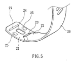
- FIG. 5 shows another alternate form of the hose clamp according to the present invention (the screw holder not shown).
- FIG. 6 is an exploded view of still another alternate form of the hose clamp according to the present invention.
- FIG. 7 is a perspective view of still another alternate form of the hose clamp according to the present invention.
- FIG. 8 is a perspective view of still another alternate form of the hose clamp according to the present invention.
- a hose clamp in accordance with one embodiment of the present invention is shown comprised of a binding belt 20 and a screw holder 30 mounted with a screw 10 .
- the binding belt 20 has a flat head 21 , a protruded portion 22 adjacent to the flat head 21 , a locating hole 23 formed in the protruded portion 22 , a through hole 24 cut through the top and bottom surfaces of the flat head 21 , two welding flanges 25 protruded from the bottom surface of the flat head 21 at two opposite lateral sides of the through hole 24 , and two stop blocks 26 protruded from the bottom surface of the flat head 21 in front of the through hole 24 .
- the screw holder 30 comprises two mounting plates 31 symmetrically disposed at two sides. Each mounting plate 31 has a positioning rod 32 .
- the screw holder 30 is attached to the top surface of the flat head 21 of the binding belt 20 , and then the mounting plates 31 are respectively bent inwards and clamped on the bottom surface of the flat head 21 of the binding belt 20 and stopped between the stop blocks 26 and the protruded portion 22 , keeping the positioning rods 32 engaged into the locating hole 23 , and then mounting plates 31 are fixedly fastened to the welding flanges 25 by spot welding. H.
- the mounting plates 31 of the screw holder 30 are stopped between the stop blocks 26 and the protruded portion 22 and because the positioning rods 32 of the mounting plates 31 are respectively engaged into the locating hole 23 of the binding belt 20 , rotating the screw 10 to fasten up the binding belt 20 does not cause the screw holder 30 to break or to disconnect from the flat head 21 . Further, because the mounting plates 31 are respectively welded to the welding flanges 25 , the screw holder 30 is maintained firmly secured to the flat head 21 of the binding belt 20 .
- the hose clamp may be variously embodied.
- a transverse stop rib 27 is provided at the flat head 21 to substitute for the aforesaid stop blocks 26 .
- the two mounting plates 31 of the screw holder 30 each have a welding flange 33 for welding to the flat bottom surface of the flat head 21 of the binding belt 20 .
- FIG. 4 there are three stop blocks 26 protruded from the bottom surface of the flat head 21 and transversely aligned in a line in front of the through hole 24 .
- a transverse stop rib 27 is provided at the flat head 21 to substitute for the aforesaid stop blocks 26 .
- the two mounting plates 31 of the screw holder 30 each have a welding flange 33 for welding to the flat bottom surface of the flat head 21 of the binding belt 20 .
- the binding belt 20 has a series of teeth 28 arranged around the outer (top) surface thereof for engagement with the screw 10 .
- the binding belt 20 has a first series of teeth 28 arranged around the outer (top) surface thereof for engagement with the screw 10 and a second series of teeth 29 arranged around the inner (bottom) surface thereof for engaging the peripheral wall of the hose to be affixed.
- FIGS. 2-8 A prototype of hose clamp has been constructed with the features of FIGS. 2-8 .
- the hose clamp functions smoothly to provide all the features discussed earlier.
Landscapes
- Engineering & Computer Science (AREA)
- General Engineering & Computer Science (AREA)
- Mechanical Engineering (AREA)
- Clamps And Clips (AREA)
Abstract
A hose clamp includes a binding belt, which has a flat head, a protruded portion adjacent to the flat head, a locating hole formed in the protruded portion, a through hole cut through the flat head, two bottom welding flanges at two sides of the through hole, and two bottom stop blocks in front of the through hole, and a screw holder attached to the top surface of the flat head to hold a screw for joining the ends of the binding belt and having two mounting plates respectively clamped on the bottom surface of the flat head and stopped between the stop blocks and the protruded portion and respectively welded to the welding flanges by spot welding, the mounting plates each having a positioning rod respectively engaged into the locating hole in the protruded portion.
Description
- 1. Field of the Invention
- The present invention relates to a hose clamp for fastening a hose to a pipe and more particularly, to a high-strength hose clamp, which is durable in use.
- 2. Description of the Related Art
-
FIGS. 1A and 1B show a hose clamp according to the prior art. According to this design, the hose clamp comprises abinding belt 11, and ascrew holder 15 holding ascrew 10. Thebinding belt 11 has a throughhole 14 in the flat head thereof, twoside notches 13 at two opposite lateral sides of the flat head, and fourstop flanges 12 at two ends of each of theside notches 13. Thescrew holder 15 has twomounting plates 16 respectively fastened to theside notches 13 and stopped between thestop flanges 12 and locatingrods 17 respectively extended from themounting plates 16 at two sides and inserted through the throughhole 14 from the back side toward the front side and then respectively clamped on the front surface of the flat head of thebinding belt 11 in four corners around the throughhole 14. This design of hose clamp is still not satisfactory in function because of the following drawbacks: - 1. When the user rotating the
screw 10 to fasten up the hose clamp, the torsional force produced from the rotary motion of thescrew 10 may cause the locatingrods 17 to deform and to disengage from the flat head of the binding belt 11 (see the imaginary line shown inFIG. 1C ). - 2. When rotating the
screw 10 to fasten up the hose clamp, the torsional force thus produced may cause themounting plates 16 to deform and to disengage from theside notches 13 of the flat head of thebinding belt 11. - The present invention has been accomplished under the circumstances in view. It is the main object of the present invention to provide hose clamp, which has a high strength and is durable in use.
- To achieve this and other objects of the present invention, the hose clamp comprises a binding belt, the binding belt having a flat head, the flat head having a top surface and a bottom surface, a protruded portion adjacent to the flat head, a locating hole formed in the protruded portion, a through hole cut through the flat head, two welding flanges protruded from the bottom surface of the flat head at two opposite lateral sides of the through hole, and a plurality of stop blocks protruded from the bottom surface of the flat head in front of the through hole; and a screw holder fastened to the flat head of the binding belt to hold a screw for joining the ends of the binding belt, the screw holder comprising two mounting plates respectively clamped on the bottom surface of the flat head and stopped between the stop blocks and the protruded portion and respectively welded to the welding flanges by spot welding, the mounting plates each having a positioning rod respectively engaged into the locating hole in the protruded portion.
-
FIG. 1A is an exploded view of a hose clamp according to the prior art. -
FIG. 1B is an assembly view in an enlarged scale of the hose clamp according to the prior art. -
FIG. 1C is a schematic sectional view showing a breaking status of the hose clamp according to the prior art. -
FIG. 2A is an exploded view of a hose clamp according to the present invention. -
FIG. 2B is an assembly view of the hose clamp according to the present invention. -
FIG. 3 is a schematic sectional view showing the fastening operation of the hose clamp according to the present invention. -
FIG. 4 shows an alternate form of the hose clamp according to the present invention (the screw holder not shown). -
FIG. 5 shows another alternate form of the hose clamp according to the present invention (the screw holder not shown). -
FIG. 6 is an exploded view of still another alternate form of the hose clamp according to the present invention. -
FIG. 7 is a perspective view of still another alternate form of the hose clamp according to the present invention. -
FIG. 8 is a perspective view of still another alternate form of the hose clamp according to the present invention. - Referring to
FIGS. 2A, 2B , and 3, a hose clamp in accordance with one embodiment of the present invention is shown comprised of abinding belt 20 and ascrew holder 30 mounted with ascrew 10. - The
binding belt 20 has aflat head 21, aprotruded portion 22 adjacent to theflat head 21, a locatinghole 23 formed in theprotruded portion 22, a throughhole 24 cut through the top and bottom surfaces of theflat head 21, twowelding flanges 25 protruded from the bottom surface of theflat head 21 at two opposite lateral sides of the throughhole 24, and twostop blocks 26 protruded from the bottom surface of theflat head 21 in front of the throughhole 24. - The
screw holder 30 comprises twomounting plates 31 symmetrically disposed at two sides. Eachmounting plate 31 has apositioning rod 32. - During installation, the
screw holder 30 is attached to the top surface of theflat head 21 of thebinding belt 20, and then themounting plates 31 are respectively bent inwards and clamped on the bottom surface of theflat head 21 of thebinding belt 20 and stopped between thestop blocks 26 and theprotruded portion 22, keeping thepositioning rods 32 engaged into the locatinghole 23, and then mountingplates 31 are fixedly fastened to thewelding flanges 25 by spot welding. H. - Because the
mounting plates 31 of thescrew holder 30 are stopped between thestop blocks 26 and theprotruded portion 22 and because thepositioning rods 32 of themounting plates 31 are respectively engaged into the locatinghole 23 of thebinding belt 20, rotating thescrew 10 to fasten up thebinding belt 20 does not cause thescrew holder 30 to break or to disconnect from theflat head 21. Further, because themounting plates 31 are respectively welded to thewelding flanges 25, thescrew holder 30 is maintained firmly secured to theflat head 21 of thebinding belt 20. - The hose clamp may be variously embodied. According to the embodiment shown in
FIG. 4 , there are threestop blocks 26 protruded from the bottom surface of theflat head 21 and transversely aligned in a line in front of thethrough hole 24. According to the embodiment shown inFIG. 5 , atransverse stop rib 27 is provided at theflat head 21 to substitute for theaforesaid stop blocks 26. According to the embodiment shown inFIG. 6 , the twomounting plates 31 of thescrew holder 30 each have awelding flange 33 for welding to the flat bottom surface of theflat head 21 of thebinding belt 20. According to the embodiment shown inFIG. 7 , thebinding belt 20 has a series ofteeth 28 arranged around the outer (top) surface thereof for engagement with thescrew 10. According to the embodiment shown inFIG. 8 , thebinding belt 20 has a first series ofteeth 28 arranged around the outer (top) surface thereof for engagement with thescrew 10 and a second series ofteeth 29 arranged around the inner (bottom) surface thereof for engaging the peripheral wall of the hose to be affixed. - A prototype of hose clamp has been constructed with the features of
FIGS. 2-8 . The hose clamp functions smoothly to provide all the features discussed earlier. - Although particular embodiments of the invention have been described in detail for purposes of illustration various modifications and enhancements may be made without departing from the spirit and scope of the invention. Accordingly, the invention is not to be limited except as by the appended claims.
Claims (3)
1. A hose clamp comprising:
a binding belt, said binding belt having a flat head, said flat head having a top surface and a bottom surface, a protruded portion adjacent to said flat head, a locating hole formed in said protruded portion, a through hole cut through said flat head, two welding flanges protruded from the bottom surface of said flat head at two opposite lateral sides of said through hole, and a plurality of stop blocks protruded from the bottom surface of said flat head in front of said through hole; and
a screw holder fastened to said flat head of said binding belt to hold a screw for joining the ends of said binding belt, said screw holder comprising two mounting plates respectively clamped on the bottom surface of said flat head and stopped between said stop blocks and said protruded portion and respectively welded to said welding flanges by spot welding, said mounting plates each having a positioning rod respectively engaged into said locating hole in said protruded portion.
2. The hose clamp as claimed in claim 1 , wherein said stop blocks are connected to one another in a line, forming a transverse stop rib.
3. The hose clamp as claimed in claim 1 , wherein said mounting plates of said screw holder each have a welding flange respectively welded to the flat bottom surface of said flat head by spot welding.
Priority Applications (1)
| Application Number | Priority Date | Filing Date | Title |
|---|---|---|---|
| US10/949,309 US20060064854A1 (en) | 2004-09-27 | 2004-09-27 | Hose clamp |
Applications Claiming Priority (1)
| Application Number | Priority Date | Filing Date | Title |
|---|---|---|---|
| US10/949,309 US20060064854A1 (en) | 2004-09-27 | 2004-09-27 | Hose clamp |
Publications (1)
| Publication Number | Publication Date |
|---|---|
| US20060064854A1 true US20060064854A1 (en) | 2006-03-30 |
Family
ID=36097386
Family Applications (1)
| Application Number | Title | Priority Date | Filing Date |
|---|---|---|---|
| US10/949,309 Abandoned US20060064854A1 (en) | 2004-09-27 | 2004-09-27 | Hose clamp |
Country Status (1)
| Country | Link |
|---|---|
| US (1) | US20060064854A1 (en) |
Cited By (4)
| Publication number | Priority date | Publication date | Assignee | Title |
|---|---|---|---|---|
| US20110094068A1 (en) * | 2009-10-28 | 2011-04-28 | Norma Germany Gmbh | Hose clamp |
| WO2013044103A1 (en) * | 2011-09-23 | 2013-03-28 | Norma U.S. Holding Llc | Hose clamp |
| US20160083158A1 (en) * | 2011-09-23 | 2016-03-24 | Norma U.S. Holding Llc | Hose clamp |
| WO2017095683A1 (en) | 2015-11-30 | 2017-06-08 | Norma U.S. Holding Llc | Hose clamp |
Citations (8)
| Publication number | Priority date | Publication date | Assignee | Title |
|---|---|---|---|---|
| US2452806A (en) * | 1944-04-14 | 1948-11-02 | Lillian B Tetzlaff | Clamp |
| US3351989A (en) * | 1966-12-05 | 1967-11-14 | Sterling Automotive Mfg Co Inc | Hose clamp |
| US4257149A (en) * | 1978-12-07 | 1981-03-24 | Tridon Limited | Band clamp device |
| US4473928A (en) * | 1980-11-20 | 1984-10-02 | Tridon Limited | Hose clamps |
| US5560087A (en) * | 1993-07-21 | 1996-10-01 | Stant Corporation | Laterally secure hose-clamp assembly |
| US5956817A (en) * | 1998-10-12 | 1999-09-28 | Chen; Dian-Tai | Structure of tube clamp |
| US6845549B2 (en) * | 2002-04-03 | 2005-01-25 | Rasmussen Gmbh | Worm drive hose clip |
| US6860527B2 (en) * | 2001-12-07 | 2005-03-01 | Donaldson Company, Inc. | Strap clamp |
-
2004
- 2004-09-27 US US10/949,309 patent/US20060064854A1/en not_active Abandoned
Patent Citations (8)
| Publication number | Priority date | Publication date | Assignee | Title |
|---|---|---|---|---|
| US2452806A (en) * | 1944-04-14 | 1948-11-02 | Lillian B Tetzlaff | Clamp |
| US3351989A (en) * | 1966-12-05 | 1967-11-14 | Sterling Automotive Mfg Co Inc | Hose clamp |
| US4257149A (en) * | 1978-12-07 | 1981-03-24 | Tridon Limited | Band clamp device |
| US4473928A (en) * | 1980-11-20 | 1984-10-02 | Tridon Limited | Hose clamps |
| US5560087A (en) * | 1993-07-21 | 1996-10-01 | Stant Corporation | Laterally secure hose-clamp assembly |
| US5956817A (en) * | 1998-10-12 | 1999-09-28 | Chen; Dian-Tai | Structure of tube clamp |
| US6860527B2 (en) * | 2001-12-07 | 2005-03-01 | Donaldson Company, Inc. | Strap clamp |
| US6845549B2 (en) * | 2002-04-03 | 2005-01-25 | Rasmussen Gmbh | Worm drive hose clip |
Cited By (9)
| Publication number | Priority date | Publication date | Assignee | Title |
|---|---|---|---|---|
| US20110094068A1 (en) * | 2009-10-28 | 2011-04-28 | Norma Germany Gmbh | Hose clamp |
| WO2013044103A1 (en) * | 2011-09-23 | 2013-03-28 | Norma U.S. Holding Llc | Hose clamp |
| US9200737B2 (en) | 2011-09-23 | 2015-12-01 | Norma U.S. Holding Llc | Hose clamp |
| US20160083158A1 (en) * | 2011-09-23 | 2016-03-24 | Norma U.S. Holding Llc | Hose clamp |
| US9534717B2 (en) * | 2011-09-23 | 2017-01-03 | Norma U.S. Holding Llc | Hose clamp |
| WO2017095683A1 (en) | 2015-11-30 | 2017-06-08 | Norma U.S. Holding Llc | Hose clamp |
| KR20180072840A (en) * | 2015-11-30 | 2018-06-29 | 노마 유.에스. 홀딩 엘엘씨 | Hose clamp |
| EP3383760A4 (en) * | 2015-11-30 | 2019-08-07 | Norma U.S. Holding LLC | PIPE CLAMP COLLAR |
| KR102183108B1 (en) * | 2015-11-30 | 2020-11-26 | 노마 유.에스. 홀딩 엘엘씨 | Hose clamp |
Similar Documents
| Publication | Publication Date | Title |
|---|---|---|
| US7467442B2 (en) | Hose clamp | |
| JP3174688U (en) | Bicycle buckle | |
| USD462251S1 (en) | Tool handle | |
| USD507167S1 (en) | Multi function stud climbing and carpentry tool | |
| USD543604S1 (en) | Gun vise | |
| US20070063514A1 (en) | Housing type joint | |
| US20080178478A1 (en) | guide bar for a chain saw | |
| US20080314779A1 (en) | Hanger for Wrench | |
| US7556188B2 (en) | Clamping device for weld seam-backing member | |
| USD519804S1 (en) | Jig saw | |
| US5787555A (en) | Structure of tube clamp | |
| USD494427S1 (en) | Splatter screen | |
| US7464444B2 (en) | Hose clamp | |
| EP1650484A1 (en) | Hose clamp | |
| EP4600512A1 (en) | Collated-screw-band assembly having shoulder washers | |
| US7104162B1 (en) | Device for unfastening pipe fasteners | |
| US20060288825A1 (en) | Wrench assembly | |
| US6899000B1 (en) | Wrench open end having a pushing tongue | |
| CA2484672A1 (en) | Hose clamp | |
| JP4960166B2 (en) | Withdrawal hardware | |
| US7201085B1 (en) | Pivoting device for hand tools | |
| MXPA05002262A (en) | Hose clamp | |
| KR20100095055A (en) | Clamp for connecting pipe and its manufacturing method | |
| CA2584541A1 (en) | Gasket package | |
| US6912755B2 (en) | Clamping device of a rotating tool |
Legal Events
| Date | Code | Title | Description |
|---|---|---|---|
| STCB | Information on status: application discontinuation |
Free format text: ABANDONED -- FAILURE TO RESPOND TO AN OFFICE ACTION |