US20040236863A1 - Systems and methods for peer-to-peer collaboration to enhance multimedia streaming - Google Patents
Systems and methods for peer-to-peer collaboration to enhance multimedia streaming Download PDFInfo
- Publication number
- US20040236863A1 US20040236863A1 US10/444,475 US44447503A US2004236863A1 US 20040236863 A1 US20040236863 A1 US 20040236863A1 US 44447503 A US44447503 A US 44447503A US 2004236863 A1 US2004236863 A1 US 2004236863A1
- Authority
- US
- United States
- Prior art keywords
- computer
- peer
- data
- streaming
- client
- Prior art date
- Legal status (The legal status is an assumption and is not a legal conclusion. Google has not performed a legal analysis and makes no representation as to the accuracy of the status listed.)
- Granted
Links
Images


Classifications
-
- H—ELECTRICITY
- H04—ELECTRIC COMMUNICATION TECHNIQUE
- H04L—TRANSMISSION OF DIGITAL INFORMATION, e.g. TELEGRAPHIC COMMUNICATION
- H04L65/00—Network arrangements, protocols or services for supporting real-time applications in data packet communication
- H04L65/60—Network streaming of media packets
- H04L65/61—Network streaming of media packets for supporting one-way streaming services, e.g. Internet radio
- H04L65/612—Network streaming of media packets for supporting one-way streaming services, e.g. Internet radio for unicast
-
- H—ELECTRICITY
- H04—ELECTRIC COMMUNICATION TECHNIQUE
- H04L—TRANSMISSION OF DIGITAL INFORMATION, e.g. TELEGRAPHIC COMMUNICATION
- H04L65/00—Network arrangements, protocols or services for supporting real-time applications in data packet communication
- H04L65/1066—Session management
- H04L65/1101—Session protocols
-
- H—ELECTRICITY
- H04—ELECTRIC COMMUNICATION TECHNIQUE
- H04L—TRANSMISSION OF DIGITAL INFORMATION, e.g. TELEGRAPHIC COMMUNICATION
- H04L65/00—Network arrangements, protocols or services for supporting real-time applications in data packet communication
- H04L65/80—Responding to QoS
-
- H—ELECTRICITY
- H04—ELECTRIC COMMUNICATION TECHNIQUE
- H04L—TRANSMISSION OF DIGITAL INFORMATION, e.g. TELEGRAPHIC COMMUNICATION
- H04L67/00—Network arrangements or protocols for supporting network services or applications
- H04L67/01—Protocols
- H04L67/10—Protocols in which an application is distributed across nodes in the network
- H04L67/104—Peer-to-peer [P2P] networks
- H04L67/1074—Peer-to-peer [P2P] networks for supporting data block transmission mechanisms
- H04L67/1078—Resource delivery mechanisms
- H04L67/108—Resource delivery mechanisms characterised by resources being split in blocks or fragments
-
- H—ELECTRICITY
- H04—ELECTRIC COMMUNICATION TECHNIQUE
- H04L—TRANSMISSION OF DIGITAL INFORMATION, e.g. TELEGRAPHIC COMMUNICATION
- H04L1/00—Arrangements for detecting or preventing errors in the information received
- H04L1/004—Arrangements for detecting or preventing errors in the information received by using forward error control
- H04L1/0056—Systems characterized by the type of code used
- H04L1/0057—Block codes
-
- H—ELECTRICITY
- H04—ELECTRIC COMMUNICATION TECHNIQUE
- H04L—TRANSMISSION OF DIGITAL INFORMATION, e.g. TELEGRAPHIC COMMUNICATION
- H04L1/00—Arrangements for detecting or preventing errors in the information received
- H04L1/12—Arrangements for detecting or preventing errors in the information received by using return channel
- H04L1/16—Arrangements for detecting or preventing errors in the information received by using return channel in which the return channel carries supervisory signals, e.g. repetition request signals
- H04L1/18—Automatic repetition systems, e.g. Van Duuren systems
- H04L1/1812—Hybrid protocols; Hybrid automatic repeat request [HARQ]
-
- H—ELECTRICITY
- H04—ELECTRIC COMMUNICATION TECHNIQUE
- H04L—TRANSMISSION OF DIGITAL INFORMATION, e.g. TELEGRAPHIC COMMUNICATION
- H04L1/00—Arrangements for detecting or preventing errors in the information received
- H04L2001/0092—Error control systems characterised by the topology of the transmission link
- H04L2001/0097—Relays
Definitions
- the systems and methods described herein relate to multimedia streaming. More particularly, the systems and methods described herein relate to using peer-to-peer collaboration to enhance streaming of multimedia content.
- C-S client-server
- peer-to-peer technology which is more robust and may be more efficient, than the pure C-S model.
- peer-to-peer streaming multiple users participating in a video streaming session are organized into an application-level multicast tree structure. All users except the root (i.e. the server) and the leaves (i.e. users that have no egressive links to other users) not only receive data but also relay the data to downstream users.
- FIG. 1 A diagram of an application-level multicast tree structure 100 is shown in FIG. 1.
- the application-level multicast tree structure 100 includes a server 102 that serves as the root of the structure.
- the server 102 communicates with multiple first-tier clients 104 , 106 , which in turn communicate with multiple second-tier clients 108 , 110 , 112 , 114 (i.e. “leaves” ).
- the server 102 communicates with the first-tier clients 104 , 106 which, in turn, communicate with the second-tier clients 108 - 114 via vertical communication channels 120 .
- the application-level multicast tree structure 100 is a limited depiction and, in practice, can have many more than three tiers and/or more or less clients located on each tier.
- the application-level multicast mimics behavior of an Internet Protocol (IP) multicast in bandwidth efficiency, i.e. there is only one copy of data transmitted over any shared link. However, that copy of data is conveyed via unicast. In other words, the application-level multicast tree is built out of a set of unicast sessions.
- IP Internet Protocol
- Application-level multicast gives rise to several problems-such as network congestion, bandwidth inefficiency, high server load, etc.—that can easily denigrate the end user streaming experience.
- a peer-paired pyramid streaming (P 3 S) architecture is provided to take advantage of additional bandwidth that is available between connected clients (i.e. a tier in a multicast tree concept) but not utilized in an application-level multicast.
- the P 3 S architecture is basically a hybrid client-server and peer-to-peer structure. It not only enables functionalities that are very close to existing application-level multicast frameworks in terms of bandwidth efficiency and server load, but also can help much on mutual quality enhancement.
- clients at the same level are coupled and peer-pairs are formed. Through the mutual help from the peer receivers, i.e. the two peers in a peer-pair, certain advantages are realized.
- each client receives a different part of a multimedia content stream.
- the different parts are then shared between connected clients to take advantage of the additional bandwidth referenced above.
- a parent can transmit different portions of the content to each child and let them complement each other to achieve higher quality.
- a topmost node in a diagram is a media server that originates the streaming process. It sends multimedia data packets to its two g children, which will then relay the received packets to their children, and so forth, until a last tier of children is reached. Before relaying packets, each child will perform necessary error recovery, data reassembly, and probably, some data allocation and pruning (rate shaping) it if receives more data than its outgoing links, i.e., the available bandwidth to its children.
- the client when a packet loss occurs at one client, the client can attempt to recover the lost packet(s) from a peer instead of requesting the server to resend the packet(s) or dropping the packet(s).
- a directory server may also be employed in a P 3 S architecture to enhance multimedia content sharing between connected clients, or peers.
- FIG. 1 is a simplified diagram of a prior art application-level multicast tree structure.
- FIG. 2 is a simplified diagram of a peer-paired pyramid streaming architecture.
- FIG. 3 a is a diagram of an exemplary network topology.
- FIG. 3 b is a diagram of a prior art application-level multicast streaming scheme.
- FIG. 3 c is a diagram showing performance of a prior art approach to a bitstream cuffing method.
- FIG. 3 d is a diagram depicting an exemplary peer-paired pyramid structure.
- FIG. 3 e is a diagram showing performance of an exemplary peer-paired pyramid approach to streaming.
- FIG. 3 f is a block diagram of a client computer.
- FIG. 3 g is a block diagram of a server computer.
- FIG. 4 is an exemplary data allocation for a peer-paired pyramid structure.
- FIG. 5 is a diagram depicting that burst losses on a shared link lead to shared packet loss.
- FIG. 6 is a diagram depicting a time delay in between packets with shared content.
- FIG. 7 is a diagram depicting burst losses on a shared link with delay.
- FIG. 8 is a flow diagram depicting a server-side methodological implementation of techniques described herein.
- FIG. 9 is a flow diagram depicting a client-side methodological implementation of techniques described herein.
- FIG. 10 is a diagram depicting an exemplary colored overlay.
- FIG. 11 is an exemplary computing environment.
- a peer-paired pyramid streaming (P 3 S) architecture is introduced in the systems and methods described herein. Also, techniques utilized in a peer-paired pyramid streaming architecture are described to exemplify how bandwidth available between peers in such an architecture may be exploited to enhance streaming quality, streaming error recovery and streaming speed.
- FIG. 2 is a simplified diagram of a peer-paired pyramid streaming (P 3 S) architecture 200 .
- the P 3 S architecture 200 includes a server 202 , first-tier client computer 204 and first-tier client computer 206 that communicate with the server 202 .
- the P 3 S architecture 200 also includes multiple second-tier client computers 208 , 210 , 212 , 214 below the first-tier client computers 204 , 206 . It is noted that the P 3 S architecture 200 is a limited depiction and may include more than a root and two tiers and/or more or less clients located on each tier.
- the server 202 communicates with the first-tier clients 204 , 206 which, in turn, communicate with the second-tier clients 208 - 214 via vertical communication channels 220 .
- the first-tier clients 204 , 206 communicate with each other via lateral communication channel 230 .
- the first-tier client 204 , 206 are peers and more particularly, a peer-pair.
- Second-tier clients 208 , 210 associated with first-tier client 204 comprise a peer-pair and communicate via lateral communication channel 240 .
- second-tier clients 212 , 214 associated with first-tier client 206 comprise a peer-pair and communicate via lateral communication channel 250 .
- the lateral communication channels 230 , 240 , 250 may be implemented as a network, such as a local area network (LAN), a wide access network (WAN), or some other type of network or connection.
- FIGS. 3 a - 3 e illustrate how performance may be improved in a P 3 S structure.
- P 3 S has the advantage of exploiting the bandwidth between peer receivers as compared with application-level multicast schemes. Using this extra bandwidth, a peer receiver has chances to exchange data with the other.
- FIG. 3 a is a diagram of an exemplary network topology 300 .
- the network topology 300 includes three nodes—N 0 302 , N 1 304 and N 2 306 that form a triangular cell.
- N 0 302 is the parent, and N 1 302 and N 2 304 are peer receivers.
- the available bandwidths among them are, respectively, 5 Mbps, 4 Mbps and 3 Mbps.
- bit streams can be aggregated to deliver better quality.
- the source stream (at N 0 302 ) has a maximum bit rate of 6 Mbps.
- a delivery tree may be constructed as shown in FIG. 3 b. A unicast session is set up for each receiver. N 0 302 will accommodate N 1 304 and N 2 306 with the maximum content their connections can handle.
- FIG. 3 c is a depiction of performance of a prior art approach to a bitstream cutting method used in configurations such as depicted in FIG. 3 a and FIG. 3 b.
- N 0 302 is capable of streaming 6 Mbps.
- N 1 304 can receive 5 Mbps of streaming data taken from N 0 302
- N 2 306 can receive 4 Mbps of streaming data from N 0 301 .
- FIG. 3 d is a depiction of a peer-paired pyramid structure 330 that is similar to the application-level multicast structure 310 shown in FIG. 3 c.
- the P 3 S structure 330 also includes N 0 302 , N 1 304 and N 2 306 .
- N 1 304 receives streaming data from N 0 at 5 Mbps
- N 2 306 receives streaming data from N 0 at 4 Mbps.
- the P 3 S structure 300 also shows that a connection between peer receivers (N 1 304 and N 2 306 ) is also utilized.
- a connection between peer receivers N 1 304 and N 2 306
- two additional logically opposite paths are set up.
- the path from N 1 304 to N 2 306 transmits streaming data at a rate of 2 Mbps.
- the opposite path from N 2 304 to N 1 304 transmits streaming data at a rate of 1 Mbps.
- FIG. 3 e depicts performance of a peer-paired pyramid approach to streaming.
- the example shown in FIG. 3 e corresponds to the P 3 S structure depicted in FIG. 3 d.
- N 0 302 can stream multimedia data at 6 Mbps. As shown here, the 6 Mbps is divided into three segments of 3 Mbps, 1 Mbps and 2 Mbps.
- N 1 304 receives data from N 0 302 at 5 Mbps and N 2 306 receives data from N 0 302 at 4 Mbps. To supplement these rates, N 1 304 receives an additional 1 Mbps of streaming data from N 2 306 , streaming data that was not transmitted to N 1 304 from N 0 302 .
- N 2 306 receives an additional 2 Mbps of streaming data from N 1 304 , streaming data that was not transmitted to N 2 306 from N 0 302 .
- both N 1 304 and N 2 306 increase streaming quality to a maximum 6 Mbps available from N 0 302 .
- T(2k+i ⁇ 2k+j) There exists a transmission session from node 2k+i to node 2k+j, denoted as T(2k+i ⁇ 2k+j), with the data rate of ⁇ T(2k+i ⁇ 2k+j) ⁇ .
- ⁇ T 0 (z) ⁇ be the aggregated data rate of node z, z ⁇ [1, N].
- the data rate of the source stream at the server (node 0) is denoted as ⁇ T 0 (0) ⁇ .
- the performance metric for data allocation is the sum of aggregated data rate of very node in P 3 S, which is expressed as: ⁇ k ⁇ ⁇ i ⁇ ⁇ T o ⁇ ( 2 ⁇ k + i ) ⁇ ( 1 )
- Equation (2-1) states that the aggregated data rate of a node comes from two sources. One is its parent and the other is its peer receiver.
- Equation (2-2) and equation (2-3) state bandwidth constraints.
- Equation (2-4) and equation (2-5) state the data rate constraints.
- equation (2-4) says that a node cannot send (to its child) more data than it can obtain (after data aggregation).
- Equation (2-5) says that a node cannot send (to its peer) more data than the portion of data it obtained directly from the parent.
- the greedy data allocation method is a simplified version of the optimal data allocation method in that it is “one-step” optimal.
- the greedy data allocation method needs to know only three bandwidths (three edges of a triangular cell) and the complexity is only O(n).
- bandwidth is allocated in balance, or as in balance as possible under the prerequisite condition that all of the available bandwidths be maximally utilized.
- FIG. 3 a network topology 300 in order to more fully explain the greedy data allocation method.
- bandwidth from N 0 302 to N 1 304 is a
- the bandwidth from N 0 302 to N 2 306 is b, where a ⁇ b.
- the bandwidth between N 1 304 and N 2 306 is c.
- the data the data rate available to N 0 is D.
- T 01 , T 02 , T 12 and T 21 be the data rate from N 0 302 to N 1 304 , N 0 302 to N 2 306 , N 1 304 to N 2 306 , and N 2 306 to N 1 304 , respectively.
- the greedy data allocation method holds to the following:
- T 12 [b, min( b+c,D ))]
- T 01 ⁇ [ 0 , max ( 0 , b - c 2 , b + a - c 2 + min ⁇ ( c 2 , b ) - ⁇ D ) ] ⁇ [ b , min ⁇ ( D , a + min ⁇ ( c 2 , b ) ) ]
- T 02 [0, b]
- T 12 [ b , min ⁇ ( b + a , max ⁇ ( c , b + c 2 , b + a + c 2 + min ⁇ ( c 2 , b ) - D ) , D ) ]
- T 21 [ max ⁇ ( 0 , b - c 2 , b + a - c 2 + min ⁇ ( c 2 , b ) - D ) , b ] .
- FIG. 3 f is a block diagram of an exemplary client computer 350 in accordance with the systems and methods described herein.
- the client computer 350 includes memory 352 that stores a client computer operating system 354 that includes a browser 355 that provides the client computer 350 with the ability to access one or more networks, such as the Internet (not shown).
- a content player 362 stored in the memory 352 is configured to play audio, video or multimedia content in conjunction with other components in the client computer 350 .
- a streaming enhancement module 356 , an error correction module 358 and a P 3 S module with color overlay generator 360 are also stored in the memory.
- the streaming enhancement module 356 is configured to carry out P 3 S functions described herein, such as receiving streaming data from a peer as well as a server, transmitting streaming data to a peer, etc.
- the error correction module 358 is configured to detect streaming data transmission errors and attempt to correct them as described herein, such as by requesting/receiving redundant data packets from a peer or a server.
- the P 3 S module with color overlay generator 360 is configured to properly join and leave a P 3 S system (i.e. group, network, etc.) by making appropriate join requests, gathering information about system computers, connecting to an appropriate parent computer, selecting an appropriate peer computer, etc.
- the memory 352 also stores miscellaneous software that may be utilized to carry out operations typically found in a client computer.
- the client computer 350 also includes a network interface card (NIC) 364 , a modem 366 , a display 368 and a processor 370 .
- the NIC 364 and the modem 366 provide a means for, among other things, receiving streaming data from a server or a peer and for transmitting streaming data to a peer.
- a user input module 372 is shown incorporated into the client computer 350 and may include a keyboard, mouse, stylus, and/or the like.
- the client computer 350 also includes an input/output (I/O) module 374 that provides a path for communicating with peripheral devices (not shown) that may be connected to the client computer 350 .
- I/O input/output
- a mass storage unit 376 and other miscellaneous hardware 378 are also included in the client computer 350 .
- client computer 350 and its elements is exemplary only and that in practice, other elements may be present in the computer or elements shown in FIG. 3 f may not be included. As long as the client computer is configured to perform the functionality set forth herein, the client computer is within the scope of the described systems and method.
- FIG. 3 g is a block diagram of an exemplary server computer 380 in accordance with the systems and methods described herein.
- the server computer 380 includes memory 382 that stores a server computer operating system 384 that controls the operations of the server computer 380 .
- a streaming application 386 is stored in the memory 382 that is configured to stream multimedia content data to one or more client computers (not shown).
- a streaming enhancement module 388 stored in the memory 382 provides streaming in accordance with the techniques described herein.
- the memory 382 also includes a P 3 S module 390 and other miscellaneous software 391 .
- the P 3 S module 390 is configured to set up a P 3 S system with multiple client computers, providing structure to the computers, identifying peer-pairs among the client computers, etc.
- the miscellaneous software 391 may include other software that is necessary to provide server functionality to the server computer 380 .
- the server computer 380 also includes a network interface card (NIC) 392 , a modem 393 , a display 394 and a processor 395 .
- the NIC 392 and the modem 393 provide a means for, among other things, transmitting streaming data from the server computer 380 to client computers.
- a user input module 396 is shown incorporated into the server computer 380 and may include a keyboard, mouse, stylus, and/or the like.
- the server computer 380 also includes an input/output (I/O) module 397 that provides a path for communicating with peripheral devices (not shown) that may be connected to the server computer 380 .
- I/O input/output
- a mass storage unit 398 and other miscellaneous hardware 399 are also included in the server computer 380 .
- server computer 380 and its elements is exemplary only and that in practice, other elements may be present in the computer or elements shown in FIG. 3 g may not be included. As long as the server computer is configured to perform the functionality set forth herein, the server computer is within the scope of the described systems and method.
- Application-level multicast streaming aims at achieving multicast functionality over a set of unicast sessions by utilizing the abundant resources of the client's uplink. Therefore, it achieves the capability of quick bandwidth adaptation like unicast and also the bandwidth efficiency like multicast without the necessity for the routers to support Internet Protocol (IP) multicast.
- IP Internet Protocol
- IP Internet Protocol
- Many research efforts are concentrated on local error recovery techniques, however, these techniques fail to work in case of shared losses where none of the clients within the locality receives the packet.
- peer-pair data exchange is used to eliminate the inefficiency of the conventional error recovery method (i.e. retransmission) of unicast streaming and to work around the difficulties of error recovery in multicast streaming.
- error recovery method i.e. retransmission
- one peer receiver detects a packet loss, it first seeks the lost packet from its partner. If the packet is not recovered after peer-pair data exchange times out, one of the receivers will issue a retransmission request to the parent as a second attempt.
- FIG. 5 is a diagram 500 depicting shared packet loss resulting from burst losses on a shared link.
- the diagram 500 represents a server 502 (S) a router 504 (X), a first receiver 506 (R 1 ) and a second receiver 508 (R 2 ). Each link is represented by an edge in the diagram 500 .
- the diagram 500 indicates a shared link (server 502 ⁇ router 504 ) between the paths to the first receiver 506 (R 1 ) and the second receiver 508 (R 2 ).
- Data packets are represented by numerals “1”, “2”, “3”, “4”, “5” and “6”, with data packets destined for the first receiver 506 (R 1 ) designated by a subscript numeral “1” and data packets destined for the second receiver 508 (R 2 ) designated by a subscript numeral “2”.
- links between the receivers (R 1 506 and R 2 508 ) are represented by edges depicted in broken lines. These links are not conceptually present in application-level multicast streaming, but they are present in peer-paired pyramid streaming.
- FIG. 6 is a diagram 600 depicting a time delay in between packets with shared content.
- the diagram 600 shows a first peer packet 602 (P 1 ) and a second peer packet 604 (P 2 ) that contain the same content but are destined for different receivers (not shown).
- a packet length is identified as L seconds.
- L is shown in units of time. L can be obtained from packet length in bits and transmission bandwidth.
- a beginning time for the transmission of the first peer packet 602 (P 1 ) is identified as t 1
- a beginning time for the transmission of the second peer packet 604 (P 2 ) is identified as t 2
- a time interval between the peer packets 602 , 604 i.e. delay
- D seconds A time interval between the peer packets 602 , 604 (i.e. delay) is identified as D seconds.
- FIG. 7 is a diagram 700 similar to the diagram 500 shown in FIG. 5, in that the diagram 700 also represents the server 502 (S), the router 504 (X), the first receiver 506 (R 1 ) and the second receiver 508 (R 2 ). Each link is represented by an edge in the diagram 700 .
- the diagram 700 illustrates an implementation to introduce some delay between peer packets by carefully scheduling the departure instance of peer packets.
- the implementation depicted in FIG. 7 simply postpones the packets destined for one of the peer receivers (e.g. R 1 506 ).
- the period of burst loss causes peer packets 3 2 , 5 1 , 4 2 and 6 1 to be dropped due to the delay of the packet transmission of peer packets destined for R 2 508 .
- the receivers When the receivers identify the packets that are missing from their respective transmission, the receivers (R 1 506 and R 2 508 ) simply request the missing packets from each other and transfer the same without having to request a retransmission from the server 502 .
- the Gilbert-Elliot model is used to model the network status.
- S 0 represents the good state and S 1 stands for error (congestion) state.
- a packet can be transmitted correctly only if the system stays in S 0 throughout the transmission process of the packet. If the duration of each state follows exponential distribution with expectations l/ ⁇ and 1/ ⁇ , respectively, then the probability distribution functions of S 0 and S 1 are
- a packet loss probability, P(E), can be derived by:
- P( ⁇ overscore (E) ⁇ ) is the probability that a packet is transmitted successfully.
- P(T ⁇ L) is the probability that the network stays in good state for at least L seconds and p 0 is the probability that the network is in good state at the beginning of a packet transmission.
- p 0 ⁇ ⁇ + ⁇
- Packet loss correlation is defined as P(E 2
- the rationale of this definition lies in the intuition that if the packet loss correlation is high, then the shared loss is very likely to happen. It is noted that the following probability formulas always hold:
- ⁇ overscore (E) ⁇ 1 ) must be derived so that P(E 2
- P 1 is the probability that the network is in the good state at time t 0 +t, given that it is in the good state at time t 0 .
- Equation [8] The conclusion that can be drawn from Equation [8] is that the packet loss correlation drops exponentially with the interval between the peer packets. Having derived that the interval between the peer packets reduces the loss correlation exponentially, it follows that some delay can be introduced (to increase the interval) to combat the shared losses. But there are no feasible techniques to accurately measure the value of ⁇ and ⁇ , thus it is hard to get a quantitative value of appropriate delay from the equation. This value should be somehow related to average length of congestion. In at least one implementation, a delay that equals min(1.5 RTT, 0.6 s) is used. However, such a value is empirical.
- the delay is adjusted on the fly.
- the two peer receivers keep on monitoring the shared losses and report to the parent.
- the parent will extend the delay if the shared loss ratio is large, and it will stop increasing the delay if more delay doesn't significantly reduce the shared loss ratio.
- Another implementation alternates packet ordering instead of introducing delays between packets.
- an average delay is described as “L” units of packets.
- a burst loss can be remedied by changing the orderings of the packets to one receiver while leaving the packet ordering to the other receiver (i.e. the peer receiver) intact.
- An advantage realized by re-ordering packets is that no bandwidth is wasted from introducing a delay between packets. It is noted that a larger L can be introduced to improve performance, but L should be constrained to a size of less than half of a length of a receiver buffer.
- a novel approach to constructing a colored overlay is described below that, when used in a peer-paired pyramid streaming structure, breaks through bottleneck bandwidth, improves reliability against node failure, and provides greater resiliency to the reality of fluctuation of network metrics.
- the colored overlay approach in a P 3 S structure improves streaming/downloading speed over a network.
- the colored overlay described below enables clients to receive data multi-path like, based on FEC (Forward Error Correction) technique.
- FEC Forward Error Correction
- An essential requirement fulfilled by the overlay is to ensure that the aggregated incoming bandwidth of each member in the overlay must exceed the required bit rate.
- FEC Forward Error Correction
- a receiver may receive packets from different senders, which could be other receivers or the server. Therefore, a natural way to 1 most effectively receive K distinguishable packets is to ensure the packets from each sender (with regard to a specific receiver) are mutually parity packets.
- each sender is colored, i.e. packets in different colors are guaranteed to be mutually parity packets.
- each node may receive data from one or more upstream nodes.
- colors should be evenly distributed in the neighborhood of each receiver.
- the out degree of a node is limited, which represents its limited available uplink bandwidth.
- a colored overlay process does not strictly conform to the P 3 S structure because a colored overlay can allow one receiver to get packets from more than one receiver and send packets to more than two receivers.
- the parents and the children of one receiver can be on different tiers. In other words, the colored overlay can be irregular.
- P 3 S structures depicted herein appear as a regular pyramid structure, it is noted that connections between peers can be zero, which represents there is actually no connection or available bandwidth.
- the traditional application layer multicast tree can actually represent the most degenerated P 3 S structure.
- Use of the colored overlay process described herein provides a more practical approach to improve streaming/downloading speed over a network.
- FIG. 10 a depicts an example of a colored overlay 701 .
- a tree-first method is utilized for its simplicity.
- members attempt to find peers with different colors than its parent. This leads to redundant edges added to the overlay (or tree).
- the colored overlay 701 includes a server node 702 and three first-tier nodes 704 , 706 , 708 having the colors red (R), green (G) and blue (B) assigned to them, respectively.
- the colored overlay 701 also includes five second-tier nodes 710 , 712 , 714 , 716 , 718 assigned colors R, B, R, G, B, respectively.
- the colored overlay 701 also includes two third-tier nodes 720 , 722 assigned the colors G and R, respectively.
- the colored overlay 701 shown in FIG. 10 a is exemplary only and can change as nodes are added or removed from the tree. Also, the colored overlay may include any practicable number of tiers, nodes and connection paths as each particular situation dictates.
- data may be received through different paths from the source.
- Each node only needs to maintain local information, including but not limited to, parent, grandparent, children, downstream peers, neighbor list, and its height (i.e. hop count to the source) in the tree.
- a node that has downstream nodes has to produce parity packets with its own color and send them out. This is a primary cost of this particular approach.
- Bootstrap Information about the server 702 (or source) may be obtained g from a public site-such as an Internet site identified by a URL (Uniform Resource Locator)-in an out-of-band manner or via a directory server. A new member that wishes to join the multicast group corresponding to the overlay 700 sends a “join” message to the sever 702 .
- a public site such as an Internet site identified by a URL (Uniform Resource Locator)-in an out-of-band manner or via a directory server.
- URL Uniform Resource Locator
- Join Policy A multicast tree is built incrementally as members join the group. Each node of the tree has its fan-out constraint, which is further decomposed into “child-tokens” and “peer-tokens.” Children are distinguished from peers so that members are organized top-down from source to leaf through parent-children relationship, and multi-paths are constructed in a peer-to-peer manner. The distinction between child-token and peer-token will help to achieve a better trade-off between latency and reliability. For efficient transfer and loop avoidance, a client prioritizes an upstream peer with a same height over those with a lower height.
- a member establishes and maintains a neighbor list with limited entries during the join process.
- Each entry of the list contains the information, such as delay, color, height and status (active or inactive), about a specific member to which the current member may connect.
- a member need not explicitly measure the bandwidth between itself and its upstream nodes. It may incrementally add peers until the desired bit rate is obtained. The required bit rate can also be achieved by first aggressively connecting to as many different-colored peers as possible and then gradually pruning connections. Rough bandwidth estimation as via monitoring the real receiving data rate may help the pruning process.
- FIG. 8 is a flow diagram 800 that depicts a methodological implementation of a join policy from the point of view of a server.
- FIG. 8 reference may be made to elements and reference numerals shown in previous figures.
- the server 0 (FIG. 4) provides server services, including multimedia streaming, to clients. This service continues as long as the server does not receive a join request from a new client (“No” branch, block 804 ).
- the server 0 receives a join request (“Yes” branch, block 804 )
- the server determines if the server has any available child-tokens that would allow the new client to connect to the server as a child thereof.
- the server If the server has available child-tokens (“Yes” branch, block 806 ), then the server 0 establishes a data connection with the client at block 814 . If there are no child-tokens available at the server (“No” branch, block 806 ), then the server redirects the client to a set of its child nodes 1 , 2 (FIG. 2) at block 808 .
- the client determines the most appropriate node of the child nodes to which it should connect and relays a new join request to the child node via the server. If that child node has an available child-token (“Yes” branch, block 812 ), then the server helps to establish a data connection between the child node and the client (block 814 ). If no child-token is available at the child node (“No” branch, block 812 ), then the process repeats blocks 808 , 810 and 812 until an appropriate node is found to which the client may connect.
- the node that has established a connection with the new client decreases a child-token count by one at block 816 .
- the server provides the new client with information about new client siblings at block 818 .
- the client uses this information to determine a color for itself, the selection of which is then transmitted to the server at block 820 and distributed to other nodes (at least neighboring nodes).
- the server facilitates data connections between the new client and one or more peers of the new client.
- FIG. 9 is a flow diagram 900 that depicts a methodological implementation of a join policy from the point of view of a client.
- the client methodological implementation corresponds with the server methodological implementation described in relation to FIG. 8.
- the client submits a join request to the server. If the server has at least one child-token available (“Yes” branch, block 904 ), then the client connects to the server at block 910 . If the server does not have a child-token available (“No” branch, block 904 ), then the client is redirected to a set of child nodes. The client measures delay (RTT) between itself and those child nodes, updates its neighbor list and send the join request to the nearest neighbor (block 906 ).
- RTT delay
- the client again determines if the node receiving the join request has at least one child-token available. If not (“No” branch, block 908 ), then the process repeats blocks 906 and 908 until a node with at least one child-token is found. When a node is found that has an available child-token (“Yes” branch, block 908 ), then the client connects to that node at block 910 and that node decreases its child-token count by one.
- the client collects information about its siblings from the server.
- the client measures delay (RTT) between itself and each of its siblings (block 914 ) and updates its neighbor list with the information at block 916 .
- RTT delay
- the client chooses a color that is the fewest among the nodes in its neighbor list (block 918 ) and provides—at least—that information to its neighbors at block 920 ).
- the client selects peers with different colors that have at least one free peer-token and establishes data connections with those peers.
- Overlay Maintenance Each member keeps local information that is a collection of information about its grandparent, parent, children, peers and neighbor list. A member periodically sends a heartbeat message to its parent and children. A member is considered dead if no heartbeat message was received during a specified time-out period. A member also periodically measures the delay between itself and its neighbors. The member updates its neighbor list while assuring the limited entries by replacing the farthest or dead nodes with nearer-than-existing neighbor(s).
- Leave/Failure Policy When a member leaves a group, its parent and upstream peers retrieve a child-token or peer-token, whichever is appropriate to their relationships with the departing member. All children of the departing member attempt to connect to their grandparent (i.e. the parent of the departing member). During the recovery process, child nodes and downstream peers of the departing member gradually update their local information and data connections.
- Overlay Improvement The overlay may be improved by moving good nodes that have larger capacity of child-tokens and peer-tokens upward and bad nodes downward. Nodes may also be transferred to a better parent to help optimize the overlay.
- a colored overlay has the following properties: (1) the overlay may help break through bottlenecks and enlarge the capacity of the system; (2) the overlay may improve reliability against node failures; and (3) the overlay is resilient to network dynamics such as packet loss, bandwidth fluctuation and delay jitter.
- FIG. 10 b is an example of a colored overlay 1000 that can help explain the properties mentioned above.
- the colored overlay 1000 includes nodes A 1002 , B 1004 , C 1006 , D 1008 , E 1010 and F 1012 .
- the edges between each pair of nodes is associated with a number that reflects a required bit rate between the pair of nodes it connects.
- the first property listed above i.e. that a colored overlay may break through bottlenecks and enlarge the capacity of the system
- the required bit rate is twenty (20) units (or 2Mbps)
- node C 1006 and node F 1012 can never achieve the desired bit rate by using any other ALM technique while they can by using the colored overlay.
- the aggregated bandwidth for both node C 1006 and node F 1012 are greater than the required bit rate. Therefore, they can achieve a “streaming-while-downloading” effect (assuming they have a large buffer). In other words, the redundant bandwidth speeds up clients' download. Further, it alleviates the impact of node failures, e.g. only node E 1010 is affected when node D 1008 fails.
- FIG. 11 shows components of typical example of such a computing system, i.e. a computer, referred by to reference numeral 1100 .
- the components shown in FIG. 11 are only examples, and are not intended to suggest any limitation as to the scope of the functionality of the invention; the invention is not necessarily dependent on the features shown in FIG. 11.
- program modules include routines, programs, objects, components, data structures, etc. that perform particular tasks or implement particular abstract data types. Tasks might also be performed by remote processing devices that are linked through a communications network.
- program modules may be located in both local and remote computer storage media.
- the instructions and/or program modules are stored at different times in the various computer-readable media that are either part of the computer or that can be read by the computer.
- Programs are typically distributed, for example, on floppy disks, CD-ROMs, DVD, or some form of communication media such as a modulated signal. From there, they are installed or loaded into the secondary memory of a computer. At execution, they are loaded at least partially into the computer's primary electronic memory.
- the invention described herein includes these and other various types of computer-readable media when such media contain instructions programs, and/or modules for implementing the steps described below in conjunction with a microprocessor or other data processors.
- the invention also includes the computer itself when programmed according to the methods and techniques described below.
- the components of computer 1100 may include, but are not limited to, a processing unit 1102 , a system memory 1104 , and a system bus 1106 that couples various system components including the system memory to the processing unit 1102 .
- the system bus 1106 may be any of several types of bus structures including a memory bus or memory controller, a peripheral bus, and a local bus using any of a variety of bus architectures.
- bus architectures include Industry Standard Architecture (ISA) bus, Micro Channel Architecture (MCA) bus, Enhanced ISA (EISAA) bus, Video Electronics Standards Association (VESA) local bus, and Peripheral Component Interconnect (PCI) bus also known as the Mezzanine bus.
- Computer 1100 typically includes a variety of computer-readable media.
- Computer-readable media can be any available media that can be accessed by computer 1100 and includes both volatile and nonvolatile media, removable and non-removable media.
- Computer-readable media may comprise computer storage media and communication media.
- Computer storage media includes volatile and nonvolatile, removable and non-removable media implemented in any method or technology for storage of information such as computer-readable instructions, data structures, program modules, or other data.
- Computer storage media includes, but is not limited to, RAM, ROM, EEPROM, flash memory or other memory technology, CD-ROM, digital versatile disks (DVD) or other optical disk storage, magnetic cassettes, magnetic tape, magnetic disk storage or other magnetic storage devices, or any other medium which can be used to store the desired information and which can be accessed by computer 1100 .
- Communication media typically embodies computer-readable instructions, data structures, program modules or other data in a modulated data signal such as a carrier wave or other transport mechanism and includes any information delivery media.
- modulated data signal means a signal that has one or more if its characteristics set or changed in such a manner as to encode information in the signal.
- communication media includes wired media such as a wired network or direct-wired connection and wireless media such as acoustic, RF, infrared and other wireless media. Combinations of any of the above should also be included within the scope of computer readable media.
- the system memory 1104 includes computer storage media in the form of volatile and/or nonvolatile memory such as read only memory (ROM) 1108 and random access memory (RAM) 1110 .
- ROM read only memory
- RAM random access memory
- BIOS basic input/output system
- RAM 1110 typically contains data and/or program modules that are immediately accessible to and/or presently being operated on by processing unit 1102 .
- FIG. 11 illustrates operating system 1114 , application programs 1116 , other program modules 1118 , and program data 1120 .
- the computer 1100 may also include other removable/non-removable, volatile/nonvolatile computer storage media.
- FIG. 11 illustrates a hard disk drive 1122 that reads from or writes to non-removable, nonvolatile magnetic media, a magnetic disk drive 1124 that reads from or writes to a removable, nonvolatile magnetic disk 1126 , and an optical disk drive 1128 that reads from or writes to a removable, nonvolatile optical disk 1130 such as a CD ROM or other optical media.
- removable/non-removable, volatile/nonvolatile computer storage media that can be used in the exemplary operating environment include, but are not limited to, magnetic tape cassettes, flash memory cards, digital versatile disks, digital video tape, solid state RAM, solid state ROM, and the like.
- the hard disk drive 1122 is typically connected to the system bus 1106 through a non-removable memory interface such as data media interface 1132
- magnetic disk drive 1124 and optical disk drive 1128 are typically connected to the system bus 1106 by a removable memory interface such as interface 1114 .
- the drives and their associated computer storage media discussed above and illustrated in FIG. 11 provide storage of computer-readable instructions, data structures, program modules, and other data for computer 1100 .
- hard disk drive 1122 is illustrated as storing operating system 1115 , application programs 1117 , other program modules 1119 , and program data 1121 .
- operating system 1115 application programs 1117 , other program modules 1119 , and program data 1121 .
- these components can either be the same as or different from operating system 1114 , application programs 1116 , other program modules 1118 , and program data 1120 .
- Operating system 1115 , application programs 1117 , other program modules 1119 , and program data 1121 are given different numbers here to illustrate that, at a minimum, they are different copies.
- a user may enter commands and information into the computer 1100 through input devices such as a keyboard 1136 and pointing device 1138 , commonly referred to as a mouse, trackball, or touch pad.
- Other input devices may include a microphone, joystick, game pad, satellite dish, scanner, or the like.
- I/O input/output
- a monitor 1142 or other type of display device is also connected to the system bus 1106 via an interface, such as a video adapter 1144 .
- computers may also include other peripheral output devices 1146 (e.g., speakers) and one or more printers 1148 , which may be connected through the I/O interface 1140 .
- the computer may operate in a networked environment using logical connections to one or more remote computers, such as a remote computing device 11 50 .
- the remote computing device 1150 may be a personal computer, a server, a router, a network PC, a peer device or other common network node, and typically includes many or all of the elements described above relative to computer 1100 .
- the logical connections depicted in FIG. 11 include a local area network (LAN) 1152 and a wide area network (WAN) 1154 .
- LAN local area network
- WAN wide area network
- the WAN 1154 shown in FIG. 11 is the Internet, the WAN 1154 may also include other networks.
- Such networking environments are commonplace in offices, enterprise-wide computer networks, intranets, and the like.
- the computer 1100 When used in a LAN networking environment, the computer 1100 is connected to the LAN 1152 through a network interface or adapter 1156 . When used in a WAN networking environment, the computer 1100 typically includes a modem 1158 or other means for establishing communications over the Internet 1154 .
- the modem 1158 which may be internal or external, may be connected to the system bus 1106 via the I/O interface 1140 , or other appropriate mechanism.
- program modules depicted relative to the computer 1100 may be stored in the remote computing device 1150 .
- FIG. 11 illustrates remote application programs 1160 as residing on remote computing device 1150 . It will be appreciated that the network connections shown are exemplary and other means of establishing a communications link between the computers may be used.
- the systems and methods as described thus provide a way to enhance multimedia streaming, improve error correction, and improve streaming/downloading speed by utilizing data connections between peer-pairs in a peer-paired pyramid streaming (P 3 S) structure.
- P 3 S peer-paired pyramid streaming
Abstract
Description
- The systems and methods described herein relate to multimedia streaming. More particularly, the systems and methods described herein relate to using peer-to-peer collaboration to enhance streaming of multimedia content.
- Most applications found on the Internet today are designed based on the simple and straightforward client-server (C-S) model. The C-S model requires a powerful server and brings severe congestion now and then due to its centralized characteristics.
- To avoid the drawbacks of the C-S model, some are turning to peer-to-peer technology, which is more robust and may be more efficient, than the pure C-S model. With peer-to-peer streaming, multiple users participating in a video streaming session are organized into an application-level multicast tree structure. All users except the root (i.e. the server) and the leaves (i.e. users that have no egressive links to other users) not only receive data but also relay the data to downstream users.
- A diagram of an application-level
multicast tree structure 100 is shown in FIG. 1. The application-levelmulticast tree structure 100 includes aserver 102 that serves as the root of the structure. Theserver 102 communicates with multiple first-tier clients tier clients server 102 communicates with the first-tier clients vertical communication channels 120. - The application-level
multicast tree structure 100 is a limited depiction and, in practice, can have many more than three tiers and/or more or less clients located on each tier. - The application-level multicast mimics behavior of an Internet Protocol (IP) multicast in bandwidth efficiency, i.e. there is only one copy of data transmitted over any shared link. However, that copy of data is conveyed via unicast. In other words, the application-level multicast tree is built out of a set of unicast sessions.
- Application-level multicast gives rise to several problems-such as network congestion, bandwidth inefficiency, high server load, etc.—that can easily denigrate the end user streaming experience.
- Systems and methods are described for peer-paired pyramid streaming. A peer-paired pyramid streaming (P 3S) architecture is provided to take advantage of additional bandwidth that is available between connected clients (i.e. a tier in a multicast tree concept) but not utilized in an application-level multicast.
- The P 3S architecture is basically a hybrid client-server and peer-to-peer structure. It not only enables functionalities that are very close to existing application-level multicast frameworks in terms of bandwidth efficiency and server load, but also can help much on mutual quality enhancement. In the P3S structure, clients at the same level are coupled and peer-pairs are formed. Through the mutual help from the peer receivers, i.e. the two peers in a peer-pair, certain advantages are realized.
- In at least one implementation, each client receives a different part of a multimedia content stream. The different parts are then shared between connected clients to take advantage of the additional bandwidth referenced above. When an outgoing link is not large enough to convey the available content, a parent can transmit different portions of the content to each child and let them complement each other to achieve higher quality.
- In a P 3S structure, a topmost node (in a diagram) is a media server that originates the streaming process. It sends multimedia data packets to its two g children, which will then relay the received packets to their children, and so forth, until a last tier of children is reached. Before relaying packets, each child will perform necessary error recovery, data reassembly, and probably, some data allocation and pruning (rate shaping) it if receives more data than its outgoing links, i.e., the available bandwidth to its children.
- In at least one implementation, when a packet loss occurs at one client, the client can attempt to recover the lost packet(s) from a peer instead of requesting the server to resend the packet(s) or dropping the packet(s).
- A directory server may also be employed in a P 3S architecture to enhance multimedia content sharing between connected clients, or peers.
- Enhanced streaming quality, streaming error recovery and downloading/streaming speed is realized by taking advantage of the additional bandwidth that is available between peers.
- A more complete understanding of exemplary methods and arrangements of the present invention may be had by reference to the following detailed description when taken in conjunction with the accompanying drawings wherein:
- FIG. 1 is a simplified diagram of a prior art application-level multicast tree structure.
- FIG. 2 is a simplified diagram of a peer-paired pyramid streaming architecture.
- FIG. 3 a is a diagram of an exemplary network topology.
- FIG. 3 b is a diagram of a prior art application-level multicast streaming scheme.
- FIG. 3 c is a diagram showing performance of a prior art approach to a bitstream cuffing method.
- FIG. 3 d is a diagram depicting an exemplary peer-paired pyramid structure.
- FIG. 3 e is a diagram showing performance of an exemplary peer-paired pyramid approach to streaming.
- FIG. 3 f is a block diagram of a client computer.
- FIG. 3 g is a block diagram of a server computer.
- FIG. 4 is an exemplary data allocation for a peer-paired pyramid structure.
- FIG. 5 is a diagram depicting that burst losses on a shared link lead to shared packet loss.
- FIG. 6 is a diagram depicting a time delay in between packets with shared content.
- FIG. 7 is a diagram depicting burst losses on a shared link with delay.
- FIG. 8 is a flow diagram depicting a server-side methodological implementation of techniques described herein.
- FIG. 9 is a flow diagram depicting a client-side methodological implementation of techniques described herein.
- FIG. 10 is a diagram depicting an exemplary colored overlay.
- FIG. 11 is an exemplary computing environment.
- The following describes systems and methods for using peer-to-peer collaboration to enhance streaming of multimedia content. A peer-paired pyramid streaming (P 3S) architecture is introduced in the systems and methods described herein. Also, techniques utilized in a peer-paired pyramid streaming architecture are described to exemplify how bandwidth available between peers in such an architecture may be exploited to enhance streaming quality, streaming error recovery and streaming speed.
- Peer-Paired Pyramid Streaming Architecture
- FIG. 2 is a simplified diagram of a peer-paired pyramid streaming (P 3S)
architecture 200. The P3Sarchitecture 200 includes aserver 202, first-tier client computer 204 and first-tier client computer 206 that communicate with theserver 202. The P3Sarchitecture 200 also includes multiple second-tier client computers tier client computers architecture 200 is a limited depiction and may include more than a root and two tiers and/or more or less clients located on each tier. - The
server 202 communicates with the first-tier clients vertical communication channels 220. In addition, the first-tier clients lateral communication channel 230. In this depiction, the first-tier client - Second-
tier clients tier client 204 comprise a peer-pair and communicate vialateral communication channel 240. Similarly, second-tier clients tier client 206 comprise a peer-pair and communicate vialateral communication channel 250. Thelateral communication channels - Techniques that exploit bandwidth that is available in the lateral connection channels in addition to bandwidth that is available in the vertical communication channels will be discussed in greater detail, below.
- As previously discussed, the main idea of application-level multicast streaming is to construct a tree structure out of a set of unicast paths between session participants. It is bandwidth efficient, since only one copy of data is transmitted over any shared unicast path. However, after the application-level multicast tree is built up, there is still some extra bandwidth available between those conceptually unconnected nodes.
- Performance Enhancement with P 3S
- FIGS. 3 a-3 e illustrate how performance may be improved in a P3S structure. P3S has the advantage of exploiting the bandwidth between peer receivers as compared with application-level multicast schemes. Using this extra bandwidth, a peer receiver has chances to exchange data with the other.
- FIG. 3 a is a diagram of an
exemplary network topology 300. Thenetwork topology 300 includes three nodes—N 0 302,N 1 304 andN 2 306 that form a triangular cell.N 0 302 is the parent, andN 1 302 andN 2 304 are peer receivers. The available bandwidths among them are, respectively, 5 Mbps, 4 Mbps and 3 Mbps. - Assume a scalable coding scheme, such as FGS (Fine Granular Scalable) or PFGS (Progressive Fine Granular Scalable) is used to compress the stream. In such a case, the bit streams can be aggregated to deliver better quality. Assume the source stream (at N 0 302) has a maximum bit rate of 6 Mbps. In existing application-level multicast streaming schemes, a delivery tree may be constructed as shown in FIG. 3b. A unicast session is set up for each receiver.
N 0 302 will accommodateN 1 304 andN 2 306 with the maximum content their connections can handle. - FIG. 3 c is a depiction of performance of a prior art approach to a bitstream cutting method used in configurations such as depicted in FIG. 3a and FIG. 3b.
N 0 302 is capable of streaming 6 Mbps.N 1 304 can receive 5 Mbps of streaming data taken fromN 0 302, andN 2 306 can receive 4 Mbps of streaming data from N0 301. - FIG. 3 d is a depiction of a peer-paired
pyramid structure 330 that is similar to the application-level multicast structure 310 shown in FIG. 3c. The P3S structure 330 also includesN 0 302,N 1 304 andN 2 306.N 1 304 receives streaming data from N0 at 5 Mbps, andN 2 306 receives streaming data from N0 at 4 Mbps. - However, the P 3S structure 300 also shows that a connection between peer receivers (
N 1 304 and N2 306) is also utilized. In the present example, two additional logically opposite paths are set up. The path fromN 1 304 toN 2 306 transmits streaming data at a rate of 2 Mbps. The opposite path fromN 2 304 toN 1 304 transmits streaming data at a rate of 1 Mbps. - With such data allocation and the data exchanges between the two peer clients (
N 1 304 and N2 306), the final presentation qualities of both clients can be improved to 6 Mbps. - FIG. 3 e depicts performance of a peer-paired pyramid approach to streaming. The example shown in FIG. 3e corresponds to the P3S structure depicted in FIG. 3d.
- Again,
N 0 302 can stream multimedia data at 6 Mbps. As shown here, the 6 Mbps is divided into three segments of 3 Mbps, 1 Mbps and 2 Mbps.N 1 304 receives data fromN 0 302 at 5 Mbps andN 2 306 receives data fromN 0 302 at 4 Mbps. To supplement these rates,N 1 304 receives an additional 1 Mbps of streaming data fromN 2 306, streaming data that was not transmitted toN 1 304 fromN 0 302. Likewise,N 2 306 receives an additional 2 Mbps of streaming data fromN 1 304, streaming data that was not transmitted toN 2 306 fromN 0 302. As a result, bothN 1 304 andN 2 306 increase streaming quality to a maximum 6 Mbps available fromN 0 302. - The example described above shows only one element cell of the P 3S structure. But the effect of such mutual help between peers will propagate to lower tiers because it prepares better sources for subsequent tiers. Techniques are described below that show how overall (global) throughput of the entire session can be maximized.
- Optimal Data Allocation
- Given a complete P 3S structure with L levels, the number of receivers, N, equals
Σ l=1 L2l=2L+1−2. Receivers are labeled in a breadth-first fashion as 1, 2, . . . , N, and a server is labeled as 0. FIG. 4 is a diagram depicting an exemplary data allocation for a P3S structure having L=3 and N=14. - For the sake of example, assume k ∈[0, N/2−1], i,j∈{1,2} and i≠j. The topology meets the following conditions: a
- There exists a unidirectional pate from node k to node 2K+1, with the available bandwidth of B(k→2K+i); and
- There exists a bi-directional path between node 2k+i and node 2K+j, with the available bandwidth of B(2k+1⇄2K+2).
- The unicast transmissions meet the following conditions:
- There exists a transmission session from node k to node 2k+i, denoted as T(k→2k+i), with the data rate of ∥T(k→2k+i)∥; and
- There exists a transmission session from node 2k+i to node 2k+j, denoted as T(2k+i→2k+j), with the data rate of ∥T(2k+i→2k+j)∥.
- Let ∥T 0(z)∥ be the aggregated data rate of node z, z ∈[1, N]. The data rate of the source stream at the server (node 0) is denoted as ∥T0(0)∥. The performance metric for data allocation is the sum of aggregated data rate of very node in P3S, which is expressed as:

- The optimal data allocation problem is then formulated as:

- and the constraints are:
- ∥T 0(2k+i)∥=∥T(k→2k+i)∥+∥T(2k+j→2k+i)∥ (2-1)
- T(k→2k+i)∥≦B(k→2k+i) (2-2)
- ∥T(2k+i→2k+j)∥+∥T(2k+j→2k+i)∥≦B(2k+1⇄2) (2-3)
- ∥T(k→2k+i)∥≦T 0(k)∥ (2-4)
- ∥T(2k+i→2k+j)∥≦∥T(k→2k+i) (2-5)
- ∥T 0(2k+i)∥≦0 (2-6)
- ∥T(k→2k+i)∥≦0 (2-7)
- ∥T(2k+i→2k+j)≧0 (2-8)
- Each constraint has a specific physical meaning. Equation (2-1) states that the aggregated data rate of a node comes from two sources. One is its parent and the other is its peer receiver. Equation (2-2) and equation (2-3) state bandwidth constraints. Equation (2-4) and equation (2-5) state the data rate constraints. To elaborate, equation (2-4) says that a node cannot send (to its child) more data than it can obtain (after data aggregation). Equation (2-5) says that a node cannot send (to its peer) more data than the portion of data it obtained directly from the parent. The other constraints are easily understood by those skilled in the art.
- With the formulation of the target and all the constraints, the problem turns out to be a linear programming problem. It can be solved with some existing linear programming algorithm, such as the simplex method.
- Greedy Data Allocation
- Since the optimal data allocation described above may take an undesirable amount of time to collect all the necessary constraints (the complexity is O(2 n)), it is desirable to have a simpler method of determining data allocation while allowing a slight tradeoff in performance.
- Such a method is described below and is referred to as the greedy data allocation method. The greedy data allocation method is a simplified version of the optimal data allocation method in that it is “one-step” optimal. The greedy data allocation method needs to know only three bandwidths (three edges of a triangular cell) and the complexity is only O(n).
- Given the three bandwidths (plus the data rate available at the parent node), there are several methods that can achieve maximum overall throughput of the cell. In at least one implementation, to embody fairness in data allocation, bandwidth is allocated in balance, or as in balance as possible under the prerequisite condition that all of the available bandwidths be maximally utilized.
- In other words, the benefit (help obtained from the other peer) and contribution (help offered to the other peer) should match. Only in the case that one peer receiver has achieved best quality available from the parent and there is still bandwidth left, is this remaining bandwidth allocated to the other peer.
- In the following example, reference is made to FIG. 3 a (network topology 300) in order to more fully explain the greedy data allocation method. Assume that that bandwidth from
N 0 302 toN 1 304 is a, and the bandwidth fromN 0 302 toN 2 306 is b, where a≧b. Also, assume that the bandwidth betweenN 1 304 andN 2 306 is c. - Furthermore, the data the data rate available to N 0 is D. Let T01, T02, T12 and T21 be the data rate from
N 0 302 toN 1 304,N 0 302 toN 2 306,N 1 304 toN 2 306, andN 2 306 toN 1 304, respectively. The greedy data allocation method holds to the following: - If D≦b≦a, the data allocation is trivial.
- T 01 =T 02=[0, D],
- T12=T21=0;
- If b≦D≦a,
- T 01=[0, D]
- T 02=[0, b]
- T 12 =[b,min(b+c,D))]
- T21 =0; ps
- If b≦a≦D,


- In the notation used above, the two numbers in the square brackets are the starting and the ending it rate that the client should get. The data rate is their difference. Thus, the results not only show the allocated data rate, but also instruct how the bit stream should be cut.
- Exemplary Client Computer
- FIG. 3 f is a block diagram of an
exemplary client computer 350 in accordance with the systems and methods described herein. Theclient computer 350 includesmemory 352 that stores a clientcomputer operating system 354 that includes abrowser 355 that provides theclient computer 350 with the ability to access one or more networks, such as the Internet (not shown). Acontent player 362 stored in thememory 352 is configured to play audio, video or multimedia content in conjunction with other components in theclient computer 350. - A
streaming enhancement module 356, anerror correction module 358 and a P3S module withcolor overlay generator 360 are also stored in the memory. Thestreaming enhancement module 356 is configured to carry out P3S functions described herein, such as receiving streaming data from a peer as well as a server, transmitting streaming data to a peer, etc. Theerror correction module 358 is configured to detect streaming data transmission errors and attempt to correct them as described herein, such as by requesting/receiving redundant data packets from a peer or a server. The P3S module withcolor overlay generator 360 is configured to properly join and leave a P3S system (i.e. group, network, etc.) by making appropriate join requests, gathering information about system computers, connecting to an appropriate parent computer, selecting an appropriate peer computer, etc. Thememory 352 also stores miscellaneous software that may be utilized to carry out operations typically found in a client computer. - The
client computer 350 also includes a network interface card (NIC) 364, amodem 366, adisplay 368 and aprocessor 370. TheNIC 364 and themodem 366 provide a means for, among other things, receiving streaming data from a server or a peer and for transmitting streaming data to a peer. - A
user input module 372 is shown incorporated into theclient computer 350 and may include a keyboard, mouse, stylus, and/or the like. Theclient computer 350 also includes an input/output (I/O)module 374 that provides a path for communicating with peripheral devices (not shown) that may be connected to theclient computer 350. Amass storage unit 376 and othermiscellaneous hardware 378 are also included in theclient computer 350. - It is noted that the depiction of the
client computer 350 and its elements is exemplary only and that in practice, other elements may be present in the computer or elements shown in FIG. 3f may not be included. As long as the client computer is configured to perform the functionality set forth herein, the client computer is within the scope of the described systems and method. - Exemplary Server Computer
- FIG. 3 g is a block diagram of an
exemplary server computer 380 in accordance with the systems and methods described herein. Theserver computer 380 includesmemory 382 that stores a servercomputer operating system 384 that controls the operations of theserver computer 380. Astreaming application 386 is stored in thememory 382 that is configured to stream multimedia content data to one or more client computers (not shown). Astreaming enhancement module 388 stored in thememory 382 provides streaming in accordance with the techniques described herein. - The
memory 382 also includes a P3S module 390 and othermiscellaneous software 391. The P3S module 390 is configured to set up a P3S system with multiple client computers, providing structure to the computers, identifying peer-pairs among the client computers, etc. Themiscellaneous software 391 may include other software that is necessary to provide server functionality to theserver computer 380. - The
server computer 380 also includes a network interface card (NIC) 392, amodem 393, adisplay 394 and aprocessor 395. TheNIC 392 and themodem 393 provide a means for, among other things, transmitting streaming data from theserver computer 380 to client computers. - A
user input module 396 is shown incorporated into theserver computer 380 and may include a keyboard, mouse, stylus, and/or the like. Theserver computer 380 also includes an input/output (I/O)module 397 that provides a path for communicating with peripheral devices (not shown) that may be connected to theserver computer 380. Amass storage unit 398 and othermiscellaneous hardware 399 are also included in theserver computer 380. - It is noted that the depiction of the
server computer 380 and its elements is exemplary only and that in practice, other elements may be present in the computer or elements shown in FIG. 3g may not be included. As long as the server computer is configured to perform the functionality set forth herein, the server computer is within the scope of the described systems and method. - Enhanced Error Recovery with P 3S
- Application-level multicast streaming aims at achieving multicast functionality over a set of unicast sessions by utilizing the abundant resources of the client's uplink. Therefore, it achieves the capability of quick bandwidth adaptation like unicast and also the bandwidth efficiency like multicast without the necessity for the routers to support Internet Protocol (IP) multicast. Generally, it is very difficult to perform efficient error recovery in such a framework. Many research efforts are concentrated on local error recovery techniques, however, these techniques fail to work in case of shared losses where none of the clients within the locality receives the packet.
- In a P 3S architecture, peer-pair data exchange is used to eliminate the inefficiency of the conventional error recovery method (i.e. retransmission) of unicast streaming and to work around the difficulties of error recovery in multicast streaming. When one peer receiver detects a packet loss, it first seeks the lost packet from its partner. If the packet is not recovered after peer-pair data exchange times out, one of the receivers will issue a retransmission request to the parent as a second attempt.
- In this manner, if packet losses experienced by the two peer receivers are independent, most of the packets missed at one receiver can be directly recovered from the other. Thus, the retransmission workload and bandwidth consumption of the media server can be greatly reduced.
- However, this is not the case for shared (correlated) loss. Even though different paths are set up for different unicast sessions, they may share some links ii since a path usually consists of many hops of links.
- FIG. 5 is a diagram 500 depicting shared packet loss resulting from burst losses on a shared link. The diagram 500 represents a server 502 (S) a router 504 (X), a first receiver 506 (R1) and a second receiver 508 (R2). Each link is represented by an edge in the diagram 500.
- The diagram 500 indicates a shared link (
server 502→router 504) between the paths to the first receiver 506 (R1) and the second receiver 508 (R2). Data packets are represented by numerals “1”, “2”, “3”, “4”, “5” and “6”, with data packets destined for the first receiver 506 (R1) designated by a subscript numeral “1” and data packets destined for the second receiver 508 (R2) designated by a subscript numeral “2”. Additionally, links between the receivers (R1 506 and R2 508) are represented by edges depicted in broken lines. These links are not conceptually present in application-level multicast streaming, but they are present in peer-paired pyramid streaming. - When the shared link between the
server 502 and therouter 504 becomes congested, it is likely that thereceivers receivers 506, 508) are dropped due to the burst loss occurring on the shared link. - For this case—as far as the application-level multicast streaming goes—the only hope for recovering the lost data packets is retransmission. Other approaches to data packet loss recovery in an ALM streaming structure will not work in this situation.
- To handle such a shared loss of data packets in a P 3S environment, a controlled delay may be introduced between the two unicast sessions to the two
peer receivers - A beginning time for the transmission of the first peer packet 602 (P1) is identified as t1, and a beginning time for the transmission of the second peer packet 604 (P2) is identified as t2. A time interval between the peer packets 602, 604 (i.e. delay) is identified as D seconds. The variables introduced in FIG. 6 will be discussed in greater detail, below, with respect to packet loss probability.
- FIG. 7 is a diagram 700 similar to the diagram 500 shown in FIG. 5, in that the diagram 700 also represents the server 502 (S), the router 504 (X), the first receiver 506 (R1) and the second receiver 508 (R2). Each link is represented by an edge in the diagram 700.
- The diagram 700 illustrates an implementation to introduce some delay between peer packets by carefully scheduling the departure instance of peer packets. The implementation depicted in FIG. 7 simply postpones the packets destined for one of the peer receivers (e.g. R1 506).
- In the instanced depicted by the example shown in FIG. 7, the period of burst loss causes
peer packets R2 508. - When the receivers identify the packets that are missing from their respective transmission, the receivers (
R1 506 and R2 508) simply request the missing packets from each other and transfer the same without having to request a retransmission from theserver 502. - In one implementation, the Gilbert-Elliot model is used to model the network status. S 0 represents the good state and S1 stands for error (congestion) state. A packet can be transmitted correctly only if the system stays in S0 throughout the transmission process of the packet. If the duration of each state follows exponential distribution with expectations l/λ and 1/μ, respectively, then the probability distribution functions of S0 and S1 are
- p 0(t)=λ·e(exp(−λt)) and p l(t)=μ·e(exp(−μt)
- respectively.
- A packet loss probability, P(E), can be derived by:
- P(E)=1−P(E)
- where P({overscore (E)}) is the probability that a packet is transmitted successfully.
- It is noted that if the network is in a good state at the beginning of a packet, then the packet will be correctly transmitted only if the network stays in good state for at least L seconds. If at any instant during the transmission of the packet the network goes to an error state, then the packet is considered lost. It follows that:
- P(E)=p 0 *P(T≧L)

- where P(T≧L) is the probability that the network stays in good state for at least L seconds and p 0 is the probability that the network is in good state at the beginning of a packet transmission.
- If the network is in steady state, then p 0 can be calculated as:

- It therefore follows that:

- Packet loss correlation is defined as P(E 2|E1). That is, given the first peer packet is lost, what is the probability that the second peer packet is also lost. The rationale of this definition lies in the intuition that if the packet loss correlation is high, then the shared loss is very likely to happen. It is noted that the following probability formulas always hold:
- P(E 2)=P(E 2 |E 1)·P(E 1)+P(E 2 |{overscore (E)} 1)·P({overscore (E)} 1) [1]
- and
- P(E 2 |{overscore (E)} 1)=1−P({overscore (E)} 2 |{overscore (E)} 1) [2]
- P({overscore (E)} 2|{overscore (E)}1) must be derived so that P(E2|E1) can be calculated:

- P 1 is the probability that the network is in the good state at time t0+t, given that it is in the good state at time t0. Assuming that the interval between the two peer packets (P1 602 and P2 604) is D (i.e. t2=t1+L+D), then it follows that:

- Now, P(E 2|{overscore (E)}1) may be computed as:

- If the network is in a steady state, then:
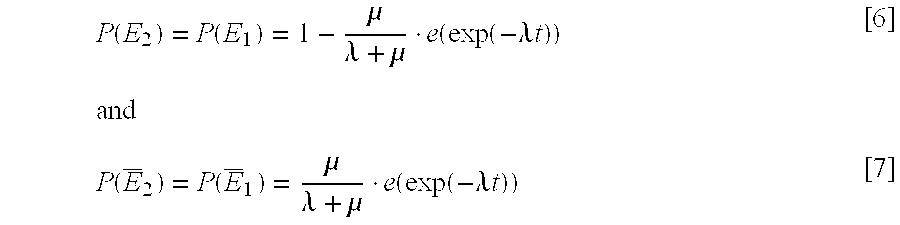
- From Equations [1], [2], [5], [6] and [7], the packet loss correlation is:

- The conclusion that can be drawn from Equation [8] is that the packet loss correlation drops exponentially with the interval between the peer packets. Having derived that the interval between the peer packets reduces the loss correlation exponentially, it follows that some delay can be introduced (to increase the interval) to combat the shared losses. But there are no feasible techniques to accurately measure the value of λ and μ, thus it is hard to get a quantitative value of appropriate delay from the equation. This value should be somehow related to average length of congestion. In at least one implementation, a delay that equals min(1.5 RTT, 0.6 s) is used. However, such a value is empirical.
- In another implementation, the delay is adjusted on the fly. The two peer receivers keep on monitoring the shared losses and report to the parent. The parent will extend the delay if the shared loss ratio is large, and it will stop increasing the delay if more delay doesn't significantly reduce the shared loss ratio.
- Another implementation alternates packet ordering instead of introducing delays between packets. In the following discussion, an average delay is described as “L” units of packets. A burst loss can be remedied by changing the orderings of the packets to one receiver while leaving the packet ordering to the other receiver (i.e. the peer receiver) intact.
- The ordering changes occur periodically with a period of 2L. For example, if L=4, then for every eight (8) packets, the ordering for the first receiver is 1, 2, 3, 4, 5, 6, 7, 8. If the ordering for the second receiver is changed to 5, 6, 7, 8, 1, 2, 3, 4, then no shared losses will occur for any burst loss having a length of four (4) or less. Any packets lost during such a burst loss will be obtainable from the peer receiver.
- The relationship between the ordering of the same packet for different receivers can be generalized as: O1=(O2+L)mod(2L). Furthermore, the theoretical performance analysis described above also applies in this case.
- An advantage realized by re-ordering packets is that no bandwidth is wasted from introducing a delay between packets. It is noted that a larger L can be introduced to improve performance, but L should be constrained to a size of less than half of a length of a receiver buffer.
- Improved Streaming Speed-Colored Overlay with P 3S
- A novel approach to constructing a colored overlay is described below that, when used in a peer-paired pyramid streaming structure, breaks through bottleneck bandwidth, improves reliability against node failure, and provides greater resiliency to the reality of fluctuation of network metrics. In other words, the colored overlay approach in a P 3S structure improves streaming/downloading speed over a network.
- The colored overlay described below enables clients to receive data multi-path like, based on FEC (Forward Error Correction) technique. An essential requirement fulfilled by the overlay is to ensure that the aggregated incoming bandwidth of each member in the overlay must exceed the required bit rate.
- To that end, the power of multi-path streaming technology is desirable. At the same time, it is desirable to maintain high bandwidth efficiency, as is seen in an application-level multicast structure. Both of these goals are met by applying the colored overlay technique in a P 3S structure.
- Forward Error Correction (FEC) technique has been overwhelmingly adopted for error protection purposes in data communications as well as in streaming applications. The receiver can still reconstruct the original data when some original packets are missing, provided that there are at least the same number of FEC packets available.
- For example, with (N, K) Reed-Solomon codes, as long as K packets out of N packets are received, the K original packets can be restored. The key here is that each receiver needs to receive K distinguishable packets.
- Due to the multi-path design, a receiver may receive packets from different senders, which could be other receivers or the server. Therefore, a natural way to 1 most effectively receive K distinguishable packets is to ensure the packets from each sender (with regard to a specific receiver) are mutually parity packets. In the present example, each sender is colored, i.e. packets in different colors are guaranteed to be mutually parity packets.
- A simple implementation for such coloring is to use Reed-Solomon codes. If there are K data packets, (M×K) parity packets are generated by using (N,K) R−S code with N=(M+1)*K. Then the (M+1)K packets can be colored with (M+1) colors such as red, green, blue, etc. A sender only sends out packets in its own color, while a receiver may receive packets in any color.
- From the foregoing discussion, there are some considerations in building an overlay. First, each node may receive data from one or more upstream nodes. Second, colors should be evenly distributed in the neighborhood of each receiver. Third, the out degree of a node is limited, which represents its limited available uplink bandwidth.
- It is noted that a colored overlay process does not strictly conform to the P 3S structure because a colored overlay can allow one receiver to get packets from more than one receiver and send packets to more than two receivers. The parents and the children of one receiver can be on different tiers. In other words, the colored overlay can be irregular.
- Although the P 3S structures depicted herein appear as a regular pyramid structure, it is noted that connections between peers can be zero, which represents there is actually no connection or available bandwidth. The traditional application layer multicast tree can actually represent the most degenerated P3S structure. Use of the colored overlay process described herein provides a more practical approach to improve streaming/downloading speed over a network.
- FIG. 10 a depicts an example of a
colored overlay 701. In the present example, a tree-first method is utilized for its simplicity. When assimilated into theoverlay 701, members attempt to find peers with different colors than its parent. This leads to redundant edges added to the overlay (or tree). - The
colored overlay 701 includes aserver node 702 and three first-tier nodes colored overlay 701 also includes five second-tier nodes colored overlay 701 also includes two third-tier nodes - It is noted that the
colored overlay 701 shown in FIG. 10a is exemplary only and can change as nodes are added or removed from the tree. Also, the colored overlay may include any practicable number of tiers, nodes and connection paths as each particular situation dictates. - From the perspective of a node, data may be received through different paths from the source. Each node only needs to maintain local information, including but not limited to, parent, grandparent, children, downstream peers, neighbor list, and its height (i.e. hop count to the source) in the tree. A node that has downstream nodes has to produce parity packets with its own color and send them out. This is a primary cost of this particular approach.
- Protocol for Building a Colored Overlay
- Bootstrap: Information about the server 702 (or source) may be obtained g from a public site-such as an Internet site identified by a URL (Uniform Resource Locator)-in an out-of-band manner or via a directory server. A new member that wishes to join the multicast group corresponding to the
overlay 700 sends a “join” message to thesever 702. - Join Policy: A multicast tree is built incrementally as members join the group. Each node of the tree has its fan-out constraint, which is further decomposed into “child-tokens” and “peer-tokens.” Children are distinguished from peers so that members are organized top-down from source to leaf through parent-children relationship, and multi-paths are constructed in a peer-to-peer manner. The distinction between child-token and peer-token will help to achieve a better trade-off between latency and reliability. For efficient transfer and loop avoidance, a client prioritizes an upstream peer with a same height over those with a lower height.
- A member establishes and maintains a neighbor list with limited entries during the join process. Each entry of the list contains the information, such as delay, color, height and status (active or inactive), about a specific member to which the current member may connect.
- A member need not explicitly measure the bandwidth between itself and its upstream nodes. It may incrementally add peers until the desired bit rate is obtained. The required bit rate can also be achieved by first aggressively connecting to as many different-colored peers as possible and then gradually pruning connections. Rough bandwidth estimation as via monitoring the real receiving data rate may help the pruning process.
- Methodological Implementation of Join Policy: Server
- FIG. 8 is a flow diagram 800 that depicts a methodological implementation of a join policy from the point of view of a server. In the following discussion of FIG. 8, reference may be made to elements and reference numerals shown in previous figures.
- At
block 802, the server 0 (FIG. 4) provides server services, including multimedia streaming, to clients. This service continues as long as the server does not receive a join request from a new client (“No” branch, block 804). When theserver 0 receives a join request (“Yes” branch, block 804), then the server determines if the server has any available child-tokens that would allow the new client to connect to the server as a child thereof. - If the server has available child-tokens (“Yes” branch, block 806), then the
server 0 establishes a data connection with the client atblock 814. If there are no child-tokens available at the server (“No” branch, block 806), then the server redirects the client to a set of itschild nodes 1, 2 (FIG. 2) atblock 808. - At
block 810, the client determines the most appropriate node of the child nodes to which it should connect and relays a new join request to the child node via the server. If that child node has an available child-token (“Yes” branch, block 812), then the server helps to establish a data connection between the child node and the client (block 814). If no child-token is available at the child node (“No” branch, block 812), then the process repeatsblocks - The node that has established a connection with the new client decreases a child-token count by one at
block 816. The server provides the new client with information about new client siblings atblock 818. The client uses this information to determine a color for itself, the selection of which is then transmitted to the server atblock 820 and distributed to other nodes (at least neighboring nodes). - At
block 822, the server facilitates data connections between the new client and one or more peers of the new client. - Methodological Implementation of Join Policy: Client
- FIG. 9 is a flow diagram 900 that depicts a methodological implementation of a join policy from the point of view of a client. The client methodological implementation corresponds with the server methodological implementation described in relation to FIG. 8.
- At
block 902, the client submits a join request to the server. If the server has at least one child-token available (“Yes” branch, block 904), then the client connects to the server atblock 910. If the server does not have a child-token available (“No” branch, block 904), then the client is redirected to a set of child nodes. The client measures delay (RTT) between itself and those child nodes, updates its neighbor list and send the join request to the nearest neighbor (block 906). - At
block 908, the client again determines if the node receiving the join request has at least one child-token available. If not (“No” branch, block 908), then the process repeatsblocks block 910 and that node decreases its child-token count by one. - At
block 912, the client collects information about its siblings from the server. The client then measures delay (RTT) between itself and each of its siblings (block 914) and updates its neighbor list with the information atblock 916. - The client chooses a color that is the fewest among the nodes in its neighbor list (block 918) and provides—at least—that information to its neighbors at block 920). At
block 922, the client selects peers with different colors that have at least one free peer-token and establishes data connections with those peers. - Overlay Maintenance: Each member keeps local information that is a collection of information about its grandparent, parent, children, peers and neighbor list. A member periodically sends a heartbeat message to its parent and children. A member is considered dead if no heartbeat message was received during a specified time-out period. A member also periodically measures the delay between itself and its neighbors. The member updates its neighbor list while assuring the limited entries by replacing the farthest or dead nodes with nearer-than-existing neighbor(s).
- Leave/Failure Policy: When a member leaves a group, its parent and upstream peers retrieve a child-token or peer-token, whichever is appropriate to their relationships with the departing member. All children of the departing member attempt to connect to their grandparent (i.e. the parent of the departing member). During the recovery process, child nodes and downstream peers of the departing member gradually update their local information and data connections.
- The recovery from failure is similar, once a member is detected to be dead.
- Overlay Improvement: The overlay may be improved by moving good nodes that have larger capacity of child-tokens and peer-tokens upward and bad nodes downward. Nodes may also be transferred to a better parent to help optimize the overlay.
- Overlay Properties
- A colored overlay has the following properties: (1) the overlay may help break through bottlenecks and enlarge the capacity of the system; (2) the overlay may improve reliability against node failures; and (3) the overlay is resilient to network dynamics such as packet loss, bandwidth fluctuation and delay jitter.
- FIG. 10 b is an example of a
colored overlay 1000 that can help explain the properties mentioned above. Thecolored overlay 1000 includes nodes A 1002,B 1004,C 1006,D 1008,E 1010 andF 1012. The edges between each pair of nodes is associated with a number that reflects a required bit rate between the pair of nodes it connects. - The first property listed above (i.e. that a colored overlay may break through bottlenecks and enlarge the capacity of the system) can be seen in FIG. 10 b. If the required bit rate is twenty (20) units (or 2Mbps),
node C 1006 andnode F 1012 can never achieve the desired bit rate by using any other ALM technique while they can by using the colored overlay. Furthermore, the aggregated bandwidth for bothnode C 1006 andnode F 1012 are greater than the required bit rate. Therefore, they can achieve a “streaming-while-downloading” effect (assuming they have a large buffer). In other words, the redundant bandwidth speeds up clients' download. Further, it alleviates the impact of node failures, e.g. onlynode E 1010 is affected whennode D 1008 fails. - Suppose a member is receiving data from M senders. The available bandwidth of each path is r 1, r2 . . . rM, respectively, each with delay d1, d2 . . . dM. Assume the size of the data block is B. Thus, the time a block successfully receives after the previous one is:

- To study how the network dynamics may impact the overall streaming jitter, a partial derivative of x with regard to d 1 is taken if there is a fluctuation of delay along the ith link, or with regard to r1 if there is a fluctuation of the available bandwidth along the ith link:

- Clearly, both the absolute values of (∂x/∂d i) and (∂x/∂ri) are far smaller than one. As a result, the influence of network dynamics is attenuated, thanks to the multi-path delivery. In practical applications, the network metrics along all the links may fluctuate simultaneously. Their effects will counteract in a statistical sense.
- Examplary Computer Environment
- The various components and functionality described herein are implemented with a computing system. FIG. 11 shows components of typical example of such a computing system, i.e. a computer, referred by to
reference numeral 1100. The components shown in FIG. 11 are only examples, and are not intended to suggest any limitation as to the scope of the functionality of the invention; the invention is not necessarily dependent on the features shown in FIG. 11. - Generally, various different general purpose or special purpose computing system configurations can be used. Examples of well known computing systems, environments, and/or configurations that may be suitable for use with the invention include, but are not limited to, personal computers, server computers, hand-held or laptop devices, multiprocessor systems, microprocessor-based systems, set top boxes, programmable consumer electronics, network PCs, minicomputers, mainframe computers, distributed computing environments that include any of the above systems or devices, and the like.
- The functionality of the computers is embodied in many cases by computer-executable instructions, such as program modules, that are executed by the computers. Generally, program modules include routines, programs, objects, components, data structures, etc. that perform particular tasks or implement particular abstract data types. Tasks might also be performed by remote processing devices that are linked through a communications network. In a distributed computing environment, program modules may be located in both local and remote computer storage media.
- The instructions and/or program modules are stored at different times in the various computer-readable media that are either part of the computer or that can be read by the computer. Programs are typically distributed, for example, on floppy disks, CD-ROMs, DVD, or some form of communication media such as a modulated signal. From there, they are installed or loaded into the secondary memory of a computer. At execution, they are loaded at least partially into the computer's primary electronic memory. The invention described herein includes these and other various types of computer-readable media when such media contain instructions programs, and/or modules for implementing the steps described below in conjunction with a microprocessor or other data processors. The invention also includes the computer itself when programmed according to the methods and techniques described below.
- For purposes of illustration, programs and other executable program components such as the operating system are illustrated herein as discrete blocks, although it is recognized that such programs and components reside at various times in different storage components of the computer, and are executed by the data processor(s) of the computer.
- With reference to FIG. 11, the components of
computer 1100 may include, but are not limited to, aprocessing unit 1102, asystem memory 1104, and asystem bus 1106 that couples various system components including the system memory to theprocessing unit 1102. Thesystem bus 1106 may be any of several types of bus structures including a memory bus or memory controller, a peripheral bus, and a local bus using any of a variety of bus architectures. By way of example, and not limitation, such architectures include Industry Standard Architecture (ISA) bus, Micro Channel Architecture (MCA) bus, Enhanced ISA (EISAA) bus, Video Electronics Standards Association (VESA) local bus, and Peripheral Component Interconnect (PCI) bus also known as the Mezzanine bus. -
Computer 1100 typically includes a variety of computer-readable media. Computer-readable media can be any available media that can be accessed bycomputer 1100 and includes both volatile and nonvolatile media, removable and non-removable media. By way of example, and not limitation, computer-readable media may comprise computer storage media and communication media. “Computer storage media” includes volatile and nonvolatile, removable and non-removable media implemented in any method or technology for storage of information such as computer-readable instructions, data structures, program modules, or other data. Computer storage media includes, but is not limited to, RAM, ROM, EEPROM, flash memory or other memory technology, CD-ROM, digital versatile disks (DVD) or other optical disk storage, magnetic cassettes, magnetic tape, magnetic disk storage or other magnetic storage devices, or any other medium which can be used to store the desired information and which can be accessed bycomputer 1100. Communication media typically embodies computer-readable instructions, data structures, program modules or other data in a modulated data signal such as a carrier wave or other transport mechanism and includes any information delivery media. The term “modulated data signal” means a signal that has one or more if its characteristics set or changed in such a manner as to encode information in the signal. By way of example, and not limitation, communication media includes wired media such as a wired network or direct-wired connection and wireless media such as acoustic, RF, infrared and other wireless media. Combinations of any of the above should also be included within the scope of computer readable media. - The
system memory 1104 includes computer storage media in the form of volatile and/or nonvolatile memory such as read only memory (ROM) 1108 and random access memory (RAM) 1110. A basic input/output system 1112 (BIOS), containing the basic routines that help to transfer information between elements withincomputer 1100, such as during start-up, is typically stored inROM 1108.RAM 1110 typically contains data and/or program modules that are immediately accessible to and/or presently being operated on byprocessing unit 1102. By way of example, and not limitation, FIG. 11 illustratesoperating system 1114,application programs 1116,other program modules 1118, andprogram data 1120. - The
computer 1100 may also include other removable/non-removable, volatile/nonvolatile computer storage media. By way of example only, FIG. 11 illustrates ahard disk drive 1122 that reads from or writes to non-removable, nonvolatile magnetic media, amagnetic disk drive 1124 that reads from or writes to a removable, nonvolatilemagnetic disk 1126, and anoptical disk drive 1128 that reads from or writes to a removable, nonvolatileoptical disk 1130 such as a CD ROM or other optical media. Other removable/non-removable, volatile/nonvolatile computer storage media that can be used in the exemplary operating environment include, but are not limited to, magnetic tape cassettes, flash memory cards, digital versatile disks, digital video tape, solid state RAM, solid state ROM, and the like. Thehard disk drive 1122 is typically connected to thesystem bus 1106 through a non-removable memory interface such asdata media interface 1132, andmagnetic disk drive 1124 andoptical disk drive 1128 are typically connected to thesystem bus 1106 by a removable memory interface such asinterface 1114. - The drives and their associated computer storage media discussed above and illustrated in FIG. 11 provide storage of computer-readable instructions, data structures, program modules, and other data for
computer 1100. In FIG. 11, for example,hard disk drive 1122 is illustrated as storing operating system 1115, application programs 1117, other program modules 1119, and program data 1121. Note that these components can either be the same as or different fromoperating system 1114,application programs 1116,other program modules 1118, andprogram data 1120. Operating system 1115, application programs 1117, other program modules 1119, and program data 1121 are given different numbers here to illustrate that, at a minimum, they are different copies. A user may enter commands and information into thecomputer 1100 through input devices such as akeyboard 1136 andpointing device 1138, commonly referred to as a mouse, trackball, or touch pad. Other input devices (not shown) may include a microphone, joystick, game pad, satellite dish, scanner, or the like. These and other input devices are often connected to theprocessing unit 1102 through an input/output (I/O)interface 1140 that is coupled to the system bus, but may be connected by other interface and bus structures, such as a parallel port, game port, or a universal serial bus (USB). Amonitor 1142 or other type of display device is also connected to thesystem bus 1106 via an interface, such as avideo adapter 1144. In addition to themonitor 1142, computers may also include other peripheral output devices 1146 (e.g., speakers) and one ormore printers 1148, which may be connected through the I/O interface 1140. - The computer may operate in a networked environment using logical connections to one or more remote computers, such as a
remote computing device 11 50. Theremote computing device 1150 may be a personal computer, a server, a router, a network PC, a peer device or other common network node, and typically includes many or all of the elements described above relative tocomputer 1100. The logical connections depicted in FIG. 11 include a local area network (LAN) 1152 and a wide area network (WAN) 1154. Although the WAN 1154 shown in FIG. 11 is the Internet, the WAN 1154 may also include other networks. Such networking environments are commonplace in offices, enterprise-wide computer networks, intranets, and the like. - When used in a LAN networking environment, the
computer 1100 is connected to theLAN 1152 through a network interface oradapter 1156. When used in a WAN networking environment, thecomputer 1100 typically includes a modem 1158 or other means for establishing communications over the Internet 1154. The modem 1158, which may be internal or external, may be connected to thesystem bus 1106 via the I/O interface 1140, or other appropriate mechanism. In a networked environment, program modules depicted relative to thecomputer 1100, or portions thereof, may be stored in theremote computing device 1150. By way of example, and not limitation, FIG. 11 illustrates remote application programs 1160 as residing onremote computing device 1150. It will be appreciated that the network connections shown are exemplary and other means of establishing a communications link between the computers may be used. - Conclusion
- The systems and methods as described thus provide a way to enhance multimedia streaming, improve error correction, and improve streaming/downloading speed by utilizing data connections between peer-pairs in a peer-paired pyramid streaming (P 3S) structure.
- Although details of specific implementations and embodiments are described above, such details are intended to satisfy statutory disclosure obligations rather than to limit the scope of the following claims. Thus, the invention as defined by the claims is not limited to the specific features described above. Rather, the invention is claimed in any of its forms or modifications that fall within the proper scope of the appended claims, appropriately interpreted in accordance with the doctrine of equivalents.
Claims (51)
Priority Applications (1)
| Application Number | Priority Date | Filing Date | Title |
|---|---|---|---|
| US10/444,475 US7577750B2 (en) | 2003-05-23 | 2003-05-23 | Systems and methods for peer-to-peer collaboration to enhance multimedia streaming |
Applications Claiming Priority (1)
| Application Number | Priority Date | Filing Date | Title |
|---|---|---|---|
| US10/444,475 US7577750B2 (en) | 2003-05-23 | 2003-05-23 | Systems and methods for peer-to-peer collaboration to enhance multimedia streaming |
Publications (2)
| Publication Number | Publication Date |
|---|---|
| US20040236863A1 true US20040236863A1 (en) | 2004-11-25 |
| US7577750B2 US7577750B2 (en) | 2009-08-18 |
Family
ID=33450668
Family Applications (1)
| Application Number | Title | Priority Date | Filing Date |
|---|---|---|---|
| US10/444,475 Expired - Fee Related US7577750B2 (en) | 2003-05-23 | 2003-05-23 | Systems and methods for peer-to-peer collaboration to enhance multimedia streaming |
Country Status (1)
| Country | Link |
|---|---|
| US (1) | US7577750B2 (en) |
Cited By (85)
| Publication number | Priority date | Publication date | Assignee | Title |
|---|---|---|---|---|
| US20030204613A1 (en) * | 2002-04-26 | 2003-10-30 | Hudson Michael D. | System and methods of streaming media files from a dispersed peer network to maintain quality of service |
| US20040152519A1 (en) * | 2000-11-14 | 2004-08-05 | Andy Wang | Multi-player game employing dynamic re-sequencing |
| US20040260814A1 (en) * | 2003-06-18 | 2004-12-23 | Utah State University | Efficient unicast-based multicast tree construction and maintenance for multimedia transmission |
| US20050004916A1 (en) * | 2003-06-13 | 2005-01-06 | Microsoft Corporation | Peer-to-peer name resolution wire protocol and message format data structure for use therein |
| US20050010674A1 (en) * | 2003-07-09 | 2005-01-13 | Nec Corporation | Content distribution system and content distribution method |
| US20050050187A1 (en) * | 2003-09-03 | 2005-03-03 | International Business Machines Corporation | Method and apparatus for support of bottleneck avoidance in an intelligent adapter |
| US20050086350A1 (en) * | 2003-10-20 | 2005-04-21 | Anthony Mai | Redundancy lists in a peer-to-peer relay network |
| US20050216559A1 (en) * | 2004-03-26 | 2005-09-29 | Microsoft Corporation | Method for efficient content distribution using a peer-to-peer networking infrastructure |
| US20050267992A1 (en) * | 2001-04-02 | 2005-12-01 | Microsoft Corporation | Peer-to-peer name resolution protocol (PNRP) and multilevel cache for use therewith |
| US20060007900A1 (en) * | 2004-07-06 | 2006-01-12 | Nortel Networks Limited | Combined user agent for packet-based communication clients |
| US20060021842A1 (en) * | 2004-07-27 | 2006-02-02 | Michael Berhan | Dual clutch assembly for a motor vehicle powertrain |
| US20060212595A1 (en) * | 2005-03-15 | 2006-09-21 | 1000 Oaks Hu Lian Technology Development (Beijing) Co., Ltd. | Method and computer-readable medium for associating sequence numbers with data blocks for distribution of data in a peer-to-peer network |
| US20060224758A1 (en) * | 2005-03-15 | 2006-10-05 | 1000 Oaks Hu Lian Technology Development Co., Ltd. | System and method for file header operation in a peer-to-peer network providing streaming services |
| US20060224757A1 (en) * | 2005-03-15 | 2006-10-05 | Han Fang | System and method for streaming service replication a in peer-to-peer network |
| US20060224756A1 (en) * | 2005-03-15 | 2006-10-05 | Mingjian Yu | System and method for error recovery for massive exit in peer-to-peer network |
| US20070076630A1 (en) * | 2005-09-30 | 2007-04-05 | Microsoft Corporation | Peer name resolution protocol simple application program interface |
| US20070101387A1 (en) * | 2005-10-31 | 2007-05-03 | Microsoft Corporation | Media Sharing And Authoring On The Web |
| US20070136476A1 (en) * | 2005-12-12 | 2007-06-14 | Isaac Rubinstein | Controlled peer-to-peer network |
| US20070186180A1 (en) * | 2005-12-30 | 2007-08-09 | Barrett Morgan | Ubiquitous navbar user interface across multiple heterogeneous digital media devices |
| US20070192798A1 (en) * | 2005-12-30 | 2007-08-16 | Barrett Morgan | Digital content delivery via virtual private network (VPN) incorporating secured set-top devices |
| US20070204321A1 (en) * | 2006-02-13 | 2007-08-30 | Tvu Networks Corporation | Methods, apparatus, and systems for providing media content over a communications network |
| US20070214279A1 (en) * | 2006-03-08 | 2007-09-13 | Samsung Electronics Co., Ltd. | Client apparatus and method of streaming content, and computer readable recording medium storing program for performing the method |
| DE102006014592A1 (en) * | 2006-03-29 | 2007-10-04 | Siemens Ag | Data transmitting method for e.g. peer-to-peer data network, involves distributing partial data streams over intermediate nodes in data network such that receiving network nodes receive all partial data streams |
| WO2007110865A1 (en) * | 2006-03-27 | 2007-10-04 | Rayv Inc. | Realtime media distribution in a p2p network |
| US20070265043A1 (en) * | 2006-04-12 | 2007-11-15 | Wang Andy Y | Team-based networked video gaming and automatic event management |
| US20070294422A1 (en) * | 2006-06-20 | 2007-12-20 | Gal Zuckerman | Methods and systems for push-to-storage |
| US20080013502A1 (en) * | 2006-02-08 | 2008-01-17 | Clark Alan R | Wireless data bus |
| WO2008051681A1 (en) * | 2006-10-24 | 2008-05-02 | Microsoft Corporation | Hybrid peer-to-peer streaming with server assistance |
| US20080201752A1 (en) * | 2007-02-16 | 2008-08-21 | At&T Knowledge Ventures, L.P. | Multicast data packet recovery system |
| US20080205394A1 (en) * | 2007-02-28 | 2008-08-28 | Deshpande Sachin G | Overlay join latency reduction using preferred peer list |
| CN101262315A (en) * | 2007-03-09 | 2008-09-10 | 三星电子株式会社 | Method and apparatus for compensating for packet loss |
| US20080219151A1 (en) * | 2007-03-07 | 2008-09-11 | Nokia Corporation | System and method for using a peer to peer mechanism to repair broadcast data in wireless digital broadcast networks |
| US20080219154A1 (en) * | 2007-03-09 | 2008-09-11 | Thales | Method of sending data packets from a server to clients via a data link that has a given error rate |
| WO2008118252A1 (en) | 2007-03-23 | 2008-10-02 | Sony Corporation | A peer-to-peer file transfer model and a client-server transfer model |
| US20080281718A1 (en) * | 2007-01-08 | 2008-11-13 | Barrett Morgan | Household network incorporating secure set-top devices |
| US20080294788A1 (en) * | 2007-05-21 | 2008-11-27 | Hong Kong Applied Science And Technology Research Institute Co., Ltd. | Systems and methods for p2p streaming |
| US20090016346A1 (en) * | 2005-11-17 | 2009-01-15 | International Business Machines Corporation | Apparatus, system and method for reliable, fast, and scalable meultcast message delivery in service overlay networks |
| US20090077254A1 (en) * | 2007-09-13 | 2009-03-19 | Thomas Darcie | System and method for streamed-media distribution using a multicast, peer-to- peer network |
| WO2009049313A1 (en) * | 2007-10-12 | 2009-04-16 | Nexgenvs | A personal media relay for rebroadcasting streaming data |
| US20090098822A1 (en) * | 2006-01-25 | 2009-04-16 | France Telecom | Burn-in system for multicast data transmission |
| US20090167841A1 (en) * | 2007-12-28 | 2009-07-02 | Industrial Technology Research Institute | System and method for multi-participant video conference without multipoint conferencing unit |
| WO2009088513A1 (en) * | 2008-01-10 | 2009-07-16 | Hewlett-Packard Development Company, L.P. | Multiway peer-to-peer media streaming |
| EP2090985A1 (en) * | 2008-02-18 | 2009-08-19 | France Telecom | Connection technique for reception by a terminal requiring at least one piece of broadcast content |
| US20090287821A1 (en) * | 2008-05-15 | 2009-11-19 | Ray-V Technologies, Ltd | Method for managing the allocation of resources to channel swarms in a peer-to-peer network |
| US20090307288A1 (en) * | 2007-02-28 | 2009-12-10 | Fujitsu Limited | Backup device |
| US20090319847A1 (en) * | 2008-06-19 | 2009-12-24 | Sony Corporation | Using different physical interface to request retransmission of packet lost on unidirectional interface |
| US20100011103A1 (en) * | 2006-09-28 | 2010-01-14 | Rayv Inc. | System and methods for peer-to-peer media streaming |
| US7657648B2 (en) | 2007-06-21 | 2010-02-02 | Microsoft Corporation | Hybrid tree/mesh overlay for data delivery |
| US20100085979A1 (en) * | 2008-10-08 | 2010-04-08 | Microsoft Corporation | Models for routing tree selection in peer-to-peer communications |
| US20100088422A1 (en) * | 2008-10-02 | 2010-04-08 | Ray-V Technologies, Ltd. | Dynamic allocation of a quota of consumer nodes connecting to a resource node of a peer-to-peer network |
| US20100110922A1 (en) * | 2008-10-31 | 2010-05-06 | Kanapathipillai Ketheesan | Method and Apparatus for Estimating Channel Bandwidth |
| US20100142547A1 (en) * | 2008-11-28 | 2010-06-10 | Alibaba Group Holding Limited | Link data transmission method, node and system |
| US7773813B2 (en) | 2005-10-31 | 2010-08-10 | Microsoft Corporation | Capture-intention detection for video content analysis |
| US20100306383A1 (en) * | 2009-05-27 | 2010-12-02 | Ray-V Technologies, Ltd. | Controlling the provision of resources for streaming of video swarms in a peer-to-peer network |
| US20100325283A1 (en) * | 2009-05-27 | 2010-12-23 | Ray-V Technologies, Ltd. | Method for dynamically adjusting resource nodes in a peer-to-peer network for delivering time-sensitive content |
| US20110002333A1 (en) * | 2008-02-08 | 2011-01-06 | Panasonic Corporation | Terminal and n-tree constructing method |
| US20110055328A1 (en) * | 2009-05-29 | 2011-03-03 | Lahr Nils B | Selective access of multi-rate data from a server and/or peer |
| US20110116503A1 (en) * | 2009-11-19 | 2011-05-19 | Krishna Balachandran | Technique For Packet Compression In An Application Level Multicast |
| US20110128958A1 (en) * | 2009-06-15 | 2011-06-02 | Thilmee Baduge | Application layer multicast (alm) tree constructing apparatus, alm tree constructing method, program, and integrated circuit |
| US7986372B2 (en) | 2004-08-02 | 2011-07-26 | Microsoft Corporation | Systems and methods for smart media content thumbnail extraction |
| US7995478B2 (en) | 2007-05-30 | 2011-08-09 | Sony Computer Entertainment Inc. | Network communication with path MTU size discovery |
| US8005957B2 (en) | 2007-12-04 | 2011-08-23 | Sony Computer Entertainment Inc. | Network traffic prioritization |
| US8015300B2 (en) | 2008-03-05 | 2011-09-06 | Sony Computer Entertainment Inc. | Traversal of symmetric network address translator for multiple simultaneous connections |
| US20110216655A1 (en) * | 2010-03-05 | 2011-09-08 | John Anthony Chen | A system and method for using ad hoc networks in cooperation with service provider networks |
| US8060626B2 (en) | 2008-09-22 | 2011-11-15 | Sony Computer Entertainment America Llc. | Method for host selection based on discovered NAT type |
| WO2011141523A1 (en) | 2010-05-13 | 2011-11-17 | Skype Limited | Processing transport packets |
| US8098730B2 (en) | 2002-11-01 | 2012-01-17 | Microsoft Corporation | Generating a motion attention model |
| US8196032B2 (en) | 2005-11-01 | 2012-06-05 | Microsoft Corporation | Template-based multimedia authoring and sharing |
| US8224985B2 (en) | 2005-10-04 | 2012-07-17 | Sony Computer Entertainment Inc. | Peer-to-peer communication traversing symmetric network address translators |
| US8352585B2 (en) * | 2008-12-08 | 2013-01-08 | Microsoft Corporation | Peer-to-peer (P2P) streaming overlay construction and optimization |
| US20130018930A1 (en) * | 2008-04-29 | 2013-01-17 | Overland Storage, Inc. | Peer-to-peer redundant file server system and methods |
| US20130290395A1 (en) * | 2012-04-26 | 2013-10-31 | Empire Technology Development Llc | Multimedia application rental and billing |
| US20130332621A1 (en) * | 2012-06-08 | 2013-12-12 | Ecole Polytechnique Federale De Lausanne (Epfl) | System and method for cooperative data streaming |
| US8650301B2 (en) | 2008-10-02 | 2014-02-11 | Ray-V Technologies, Ltd. | Adaptive data rate streaming in a peer-to-peer network delivering video content |
| TWI477112B (en) * | 2009-06-30 | 2015-03-11 | Alibaba Group Holding Ltd | Chain data transmission method, node and system |
| WO2015059041A1 (en) * | 2013-10-25 | 2015-04-30 | Peerialism AB | Aggressive prefetching |
| US9053754B2 (en) | 2004-07-28 | 2015-06-09 | Microsoft Technology Licensing, Llc | Thumbnail generation and presentation for recorded TV programs |
| US20160316009A1 (en) * | 2008-12-31 | 2016-10-27 | Google Technology Holdings LLC | Device and method for receiving scalable content from multiple sources having different content quality |
| US9578077B2 (en) | 2013-10-25 | 2017-02-21 | Hive Streaming Ab | Aggressive prefetching |
| EP2078383A4 (en) * | 2006-10-31 | 2017-04-12 | Thomson Licensing | Data recovery in heterogeneous networks using peer's cooperative networking |
| US20180007430A1 (en) * | 2008-08-13 | 2018-01-04 | At&T Intellectual Property I, L.P. | Peer-to-Peer Video Data Sharing |
| US10306021B1 (en) * | 2014-08-21 | 2019-05-28 | Amazon Technologies, Inc. | Streaming content to multiple clients |
| US10977519B2 (en) | 2011-05-13 | 2021-04-13 | Microsoft Technology Licensing, Llc | Generating event definitions based on spatial and relational relationships |
| US11064023B2 (en) | 2009-05-27 | 2021-07-13 | Verizon Media Inc. | Method for actively sharing available bandwidth to consumer nodes in a peer-to-peer network for delivery of video streams |
| US20230188609A1 (en) * | 2021-12-10 | 2023-06-15 | Topia Interactive, Inc. | Client authoritative state distribution system |
Families Citing this family (28)
| Publication number | Priority date | Publication date | Assignee | Title |
|---|---|---|---|---|
| US7272658B1 (en) | 2003-02-13 | 2007-09-18 | Adobe Systems Incorporated | Real-time priority-based media communication |
| US7818444B2 (en) | 2004-04-30 | 2010-10-19 | Move Networks, Inc. | Apparatus, system, and method for multi-bitrate content streaming |
| US8868772B2 (en) | 2004-04-30 | 2014-10-21 | Echostar Technologies L.L.C. | Apparatus, system, and method for adaptive-rate shifting of streaming content |
| US8904463B2 (en) | 2005-03-09 | 2014-12-02 | Vudu, Inc. | Live video broadcasting on distributed networks |
| US7937379B2 (en) * | 2005-03-09 | 2011-05-03 | Vudu, Inc. | Fragmentation of a file for instant access |
| US9176955B2 (en) | 2005-03-09 | 2015-11-03 | Vvond, Inc. | Method and apparatus for sharing media files among network nodes |
| US8219635B2 (en) * | 2005-03-09 | 2012-07-10 | Vudu, Inc. | Continuous data feeding in a distributed environment |
| US20080022343A1 (en) | 2006-07-24 | 2008-01-24 | Vvond, Inc. | Multiple audio streams |
| US20090025046A1 (en) * | 2005-03-09 | 2009-01-22 | Wond, Llc | Hybrid architecture for media services |
| US7191215B2 (en) * | 2005-03-09 | 2007-03-13 | Marquee, Inc. | Method and system for providing instantaneous media-on-demand services by transmitting contents in pieces from client machines |
| US8370514B2 (en) | 2005-04-28 | 2013-02-05 | DISH Digital L.L.C. | System and method of minimizing network bandwidth retrieved from an external network |
| US8683066B2 (en) | 2007-08-06 | 2014-03-25 | DISH Digital L.L.C. | Apparatus, system, and method for multi-bitrate content streaming |
| US8099511B1 (en) | 2005-06-11 | 2012-01-17 | Vudu, Inc. | Instantaneous media-on-demand |
| US20070147371A1 (en) * | 2005-09-26 | 2007-06-28 | The Board Of Trustees Of Michigan State University | Multicast packet video system and hardware |
| US7969997B1 (en) * | 2005-11-04 | 2011-06-28 | The Board Of Trustees Of The Leland Stanford Junior University | Video communications in a peer-to-peer network |
| US8122087B2 (en) | 2006-03-21 | 2012-02-21 | Aol Inc. | Matching engine for comparing data feeds with user profile criteria |
| US7660906B1 (en) * | 2006-03-27 | 2010-02-09 | Beyond Media, Llc | Data delivery system and method |
| US8296812B1 (en) | 2006-09-01 | 2012-10-23 | Vudu, Inc. | Streaming video using erasure encoding |
| JP4680860B2 (en) * | 2006-09-29 | 2011-05-11 | 富士通株式会社 | Data communication method |
| EP2135430B1 (en) * | 2007-03-20 | 2018-04-11 | Thomson Licensing | Hierarchically clustered p2p streaming system |
| US7961878B2 (en) | 2007-10-15 | 2011-06-14 | Adobe Systems Incorporated | Imparting cryptographic information in network communications |
| US20090164576A1 (en) * | 2007-12-21 | 2009-06-25 | Jeonghun Noh | Methods and systems for peer-to-peer systems |
| US8527590B2 (en) * | 2008-01-16 | 2013-09-03 | Janos Tapolcai | Solving mixed integer programs with peer-to-peer applications |
| WO2009145748A1 (en) * | 2008-05-28 | 2009-12-03 | Thomson Licensing | Multi-head hierarchically clustered peer-to-peer live streaming system |
| US8051287B2 (en) | 2008-10-15 | 2011-11-01 | Adobe Systems Incorporated | Imparting real-time priority-based network communications in an encrypted communication session |
| US8782122B1 (en) | 2014-01-17 | 2014-07-15 | Maximilian A. Chang | Automated collaboration for peer-to-peer electronic devices |
| US8782121B1 (en) | 2014-01-17 | 2014-07-15 | Maximilian A. Chang | Peer-to-peer electronic device handling of social network activity |
| US10425458B2 (en) * | 2016-10-14 | 2019-09-24 | Cisco Technology, Inc. | Adaptive bit rate streaming with multi-interface reception |
Citations (11)
| Publication number | Priority date | Publication date | Assignee | Title |
|---|---|---|---|---|
| US5878040A (en) * | 1995-11-17 | 1999-03-02 | 3Com Corporation | Coordination and control of data streams that terminate at different termination units |
| US20020161898A1 (en) * | 2000-12-20 | 2002-10-31 | Scott Hartop | Streaming of data |
| US20030050834A1 (en) * | 2001-09-07 | 2003-03-13 | Sergio Caplan | System and method for dynamic customizable interactive portal active during select computer time |
| US6735633B1 (en) * | 1999-06-01 | 2004-05-11 | Fast Forward Networks | System for bandwidth allocation in a computer network |
| US20040143672A1 (en) * | 2003-01-07 | 2004-07-22 | Microsoft Corporation | System and method for distributing streaming content through cooperative networking |
| US6975613B1 (en) * | 1999-12-06 | 2005-12-13 | Telefonaktiebolaget L M Ericsson (Publ) | System and method for scheduling communication sessions in an ad-hoc network |
| US6996064B2 (en) * | 2000-12-21 | 2006-02-07 | International Business Machines Corporation | System and method for determining network throughput speed and streaming utilization |
| US7028096B1 (en) * | 1999-09-14 | 2006-04-11 | Streaming21, Inc. | Method and apparatus for caching for streaming data |
| US7058014B2 (en) * | 2000-10-26 | 2006-06-06 | Intel Corporation | Method and apparatus for generating a large payload file |
| US7143433B1 (en) * | 2000-12-27 | 2006-11-28 | Infovalve Computing Inc. | Video distribution system using dynamic segmenting of video data files |
| US7272658B1 (en) * | 2003-02-13 | 2007-09-18 | Adobe Systems Incorporated | Real-time priority-based media communication |
-
2003
- 2003-05-23 US US10/444,475 patent/US7577750B2/en not_active Expired - Fee Related
Patent Citations (11)
| Publication number | Priority date | Publication date | Assignee | Title |
|---|---|---|---|---|
| US5878040A (en) * | 1995-11-17 | 1999-03-02 | 3Com Corporation | Coordination and control of data streams that terminate at different termination units |
| US6735633B1 (en) * | 1999-06-01 | 2004-05-11 | Fast Forward Networks | System for bandwidth allocation in a computer network |
| US7028096B1 (en) * | 1999-09-14 | 2006-04-11 | Streaming21, Inc. | Method and apparatus for caching for streaming data |
| US6975613B1 (en) * | 1999-12-06 | 2005-12-13 | Telefonaktiebolaget L M Ericsson (Publ) | System and method for scheduling communication sessions in an ad-hoc network |
| US7058014B2 (en) * | 2000-10-26 | 2006-06-06 | Intel Corporation | Method and apparatus for generating a large payload file |
| US20020161898A1 (en) * | 2000-12-20 | 2002-10-31 | Scott Hartop | Streaming of data |
| US6996064B2 (en) * | 2000-12-21 | 2006-02-07 | International Business Machines Corporation | System and method for determining network throughput speed and streaming utilization |
| US7143433B1 (en) * | 2000-12-27 | 2006-11-28 | Infovalve Computing Inc. | Video distribution system using dynamic segmenting of video data files |
| US20030050834A1 (en) * | 2001-09-07 | 2003-03-13 | Sergio Caplan | System and method for dynamic customizable interactive portal active during select computer time |
| US20040143672A1 (en) * | 2003-01-07 | 2004-07-22 | Microsoft Corporation | System and method for distributing streaming content through cooperative networking |
| US7272658B1 (en) * | 2003-02-13 | 2007-09-18 | Adobe Systems Incorporated | Real-time priority-based media communication |
Cited By (175)
| Publication number | Priority date | Publication date | Assignee | Title |
|---|---|---|---|---|
| US20040152519A1 (en) * | 2000-11-14 | 2004-08-05 | Andy Wang | Multi-player game employing dynamic re-sequencing |
| US7244181B2 (en) | 2000-11-14 | 2007-07-17 | Netamin Communication Corp. | Multi-player game employing dynamic re-sequencing |
| US20050267992A1 (en) * | 2001-04-02 | 2005-12-01 | Microsoft Corporation | Peer-to-peer name resolution protocol (PNRP) and multilevel cache for use therewith |
| US7962651B2 (en) | 2001-04-02 | 2011-06-14 | Microsoft Corporation | Peer-to-peer name resolution protocol (PNRP) and multilevel cache for use therewith |
| US9894176B2 (en) | 2002-04-26 | 2018-02-13 | Sony Corporation | Centralized selection of peers as media data sources in a dispersed peer network |
| US20030204613A1 (en) * | 2002-04-26 | 2003-10-30 | Hudson Michael D. | System and methods of streaming media files from a dispersed peer network to maintain quality of service |
| US8775657B2 (en) | 2002-04-26 | 2014-07-08 | Sony Corporation | System and methods of streamlining media files from a dispersed peer network to maintain quality of service |
| US8935315B2 (en) | 2002-04-26 | 2015-01-13 | Sony Corporation | Centralized selection of peers as media data sources in a dispersed peer network |
| US20090049185A1 (en) * | 2002-04-26 | 2009-02-19 | Hudson Michael D | System and methods of streamlining media files from a dispersed peer network to maintain quality of service |
| US20090055547A1 (en) * | 2002-04-26 | 2009-02-26 | Hudson Michael D | Mediated multi-source peer content delivery network architecture |
| US8583814B2 (en) * | 2002-04-26 | 2013-11-12 | Sony Corporation | System and methods of streamlining media files from a dispersed peer network to maintain quality of service |
| US10506064B2 (en) | 2002-04-26 | 2019-12-10 | Sony Corporation | Centralized selection of peers as media data sources in a dispersed peer network |
| US8219700B2 (en) | 2002-04-26 | 2012-07-10 | Sony Corporation | System and methods of streaming media files from a dispersed peer network to maintain quality of service |
| US20090210549A1 (en) * | 2002-04-26 | 2009-08-20 | Hudson Michael D | System and methods of streamlining media files from a dispersed peer network to maintain quality of service |
| US8098730B2 (en) | 2002-11-01 | 2012-01-17 | Microsoft Corporation | Generating a motion attention model |
| US20050004916A1 (en) * | 2003-06-13 | 2005-01-06 | Microsoft Corporation | Peer-to-peer name resolution wire protocol and message format data structure for use therein |
| US7533184B2 (en) | 2003-06-13 | 2009-05-12 | Microsoft Corporation | Peer-to-peer name resolution wire protocol and message format data structure for use therein |
| US7596595B2 (en) * | 2003-06-18 | 2009-09-29 | Utah State University | Efficient unicast-based multicast tree construction and maintenance for multimedia transmission |
| US20040260814A1 (en) * | 2003-06-18 | 2004-12-23 | Utah State University | Efficient unicast-based multicast tree construction and maintenance for multimedia transmission |
| US20050010674A1 (en) * | 2003-07-09 | 2005-01-13 | Nec Corporation | Content distribution system and content distribution method |
| US20050050187A1 (en) * | 2003-09-03 | 2005-03-03 | International Business Machines Corporation | Method and apparatus for support of bottleneck avoidance in an intelligent adapter |
| US20050086350A1 (en) * | 2003-10-20 | 2005-04-21 | Anthony Mai | Redundancy lists in a peer-to-peer relay network |
| US7685301B2 (en) * | 2003-10-20 | 2010-03-23 | Sony Computer Entertainment America Inc. | Redundancy lists in a peer-to-peer relay network |
| US20050216559A1 (en) * | 2004-03-26 | 2005-09-29 | Microsoft Corporation | Method for efficient content distribution using a peer-to-peer networking infrastructure |
| US8688803B2 (en) | 2004-03-26 | 2014-04-01 | Microsoft Corporation | Method for efficient content distribution using a peer-to-peer networking infrastructure |
| US8320349B1 (en) | 2004-07-06 | 2012-11-27 | Rockstar Consortium Us Lp | Combined user agent for packet-based communication clients |
| WO2006006051A1 (en) * | 2004-07-06 | 2006-01-19 | Nortel Networks Limited, | Combined user agent for packet-based communication clients |
| US20060007900A1 (en) * | 2004-07-06 | 2006-01-12 | Nortel Networks Limited | Combined user agent for packet-based communication clients |
| US8116286B2 (en) | 2004-07-06 | 2012-02-14 | Rockstar Bidco, LP | Combined user agent for packet-based communication clients |
| US20060021842A1 (en) * | 2004-07-27 | 2006-02-02 | Michael Berhan | Dual clutch assembly for a motor vehicle powertrain |
| US9053754B2 (en) | 2004-07-28 | 2015-06-09 | Microsoft Technology Licensing, Llc | Thumbnail generation and presentation for recorded TV programs |
| US9355684B2 (en) | 2004-07-28 | 2016-05-31 | Microsoft Technology Licensing, Llc | Thumbnail generation and presentation for recorded TV programs |
| US7986372B2 (en) | 2004-08-02 | 2011-07-26 | Microsoft Corporation | Systems and methods for smart media content thumbnail extraction |
| US20060212595A1 (en) * | 2005-03-15 | 2006-09-21 | 1000 Oaks Hu Lian Technology Development (Beijing) Co., Ltd. | Method and computer-readable medium for associating sequence numbers with data blocks for distribution of data in a peer-to-peer network |
| US20060224758A1 (en) * | 2005-03-15 | 2006-10-05 | 1000 Oaks Hu Lian Technology Development Co., Ltd. | System and method for file header operation in a peer-to-peer network providing streaming services |
| US20060224756A1 (en) * | 2005-03-15 | 2006-10-05 | Mingjian Yu | System and method for error recovery for massive exit in peer-to-peer network |
| US20060224757A1 (en) * | 2005-03-15 | 2006-10-05 | Han Fang | System and method for streaming service replication a in peer-to-peer network |
| US8255546B2 (en) * | 2005-09-30 | 2012-08-28 | Microsoft Corporation | Peer name resolution protocol simple application program interface |
| US20070076630A1 (en) * | 2005-09-30 | 2007-04-05 | Microsoft Corporation | Peer name resolution protocol simple application program interface |
| US8224985B2 (en) | 2005-10-04 | 2012-07-17 | Sony Computer Entertainment Inc. | Peer-to-peer communication traversing symmetric network address translators |
| US7773813B2 (en) | 2005-10-31 | 2010-08-10 | Microsoft Corporation | Capture-intention detection for video content analysis |
| US8180826B2 (en) | 2005-10-31 | 2012-05-15 | Microsoft Corporation | Media sharing and authoring on the web |
| US20070101387A1 (en) * | 2005-10-31 | 2007-05-03 | Microsoft Corporation | Media Sharing And Authoring On The Web |
| US8196032B2 (en) | 2005-11-01 | 2012-06-05 | Microsoft Corporation | Template-based multimedia authoring and sharing |
| US20090016346A1 (en) * | 2005-11-17 | 2009-01-15 | International Business Machines Corporation | Apparatus, system and method for reliable, fast, and scalable meultcast message delivery in service overlay networks |
| US8649296B2 (en) | 2005-11-17 | 2014-02-11 | International Business Machines Corporation | Apparatus, system and method for reliable, fast, and scalable multicast message delivery in service overlay networks |
| US8358652B2 (en) * | 2005-11-17 | 2013-01-22 | International Business Machines Corporation | Apparatus, system and method for reliable, fast, and scalable multicast message delivery in service overlay networks |
| US20070136476A1 (en) * | 2005-12-12 | 2007-06-14 | Isaac Rubinstein | Controlled peer-to-peer network |
| US7673240B2 (en) | 2005-12-30 | 2010-03-02 | Polaroid Labs, Llc | Ubiquitous navbar user interface across multiple heterogeneous digital media devices |
| US20070192798A1 (en) * | 2005-12-30 | 2007-08-16 | Barrett Morgan | Digital content delivery via virtual private network (VPN) incorporating secured set-top devices |
| US20070186180A1 (en) * | 2005-12-30 | 2007-08-09 | Barrett Morgan | Ubiquitous navbar user interface across multiple heterogeneous digital media devices |
| US20090098822A1 (en) * | 2006-01-25 | 2009-04-16 | France Telecom | Burn-in system for multicast data transmission |
| EP1989822B1 (en) * | 2006-01-25 | 2017-11-29 | Orange | Reliability system for multicast data transmission |
| US8427994B2 (en) * | 2006-01-25 | 2013-04-23 | France Telecom | Burn-in system for multicast data transmission |
| US20080013502A1 (en) * | 2006-02-08 | 2008-01-17 | Clark Alan R | Wireless data bus |
| US9860602B2 (en) | 2006-02-13 | 2018-01-02 | Tvu Networks Corporation | Methods, apparatus, and systems for providing media content over a communications network |
| US20070204321A1 (en) * | 2006-02-13 | 2007-08-30 | Tvu Networks Corporation | Methods, apparatus, and systems for providing media content over a communications network |
| US11317164B2 (en) | 2006-02-13 | 2022-04-26 | Tvu Networks Corporation | Methods, apparatus, and systems for providing media content over a communications network |
| US10917699B2 (en) | 2006-02-13 | 2021-02-09 | Tvu Networks Corporation | Methods, apparatus, and systems for providing media and advertising content over a communications network |
| US8904456B2 (en) | 2006-02-13 | 2014-12-02 | Tvu Networks Corporation | Methods, apparatus, and systems for providing media content over a communications network |
| US20070214279A1 (en) * | 2006-03-08 | 2007-09-13 | Samsung Electronics Co., Ltd. | Client apparatus and method of streaming content, and computer readable recording medium storing program for performing the method |
| US8266316B2 (en) * | 2006-03-08 | 2012-09-11 | Samsung Electronics Co., Ltd. | Client apparatus and method of streaming content, and computer readable recording medium storing program for performing the method |
| US20110173341A1 (en) * | 2006-03-27 | 2011-07-14 | Rayv Inc. | Realtime media distribution in a p2p network |
| US8095682B2 (en) | 2006-03-27 | 2012-01-10 | Rayv Inc. | Realtime media distribution in a p2p network |
| US20090248872A1 (en) * | 2006-03-27 | 2009-10-01 | Rayv Inc. | Realtime media distribution in a p2p network |
| WO2007110865A1 (en) * | 2006-03-27 | 2007-10-04 | Rayv Inc. | Realtime media distribution in a p2p network |
| US7945694B2 (en) | 2006-03-27 | 2011-05-17 | Rayv Inc. | Realtime media distribution in a p2p network |
| DE102006014592A1 (en) * | 2006-03-29 | 2007-10-04 | Siemens Ag | Data transmitting method for e.g. peer-to-peer data network, involves distributing partial data streams over intermediate nodes in data network such that receiving network nodes receive all partial data streams |
| US20070265043A1 (en) * | 2006-04-12 | 2007-11-15 | Wang Andy Y | Team-based networked video gaming and automatic event management |
| US20070294422A1 (en) * | 2006-06-20 | 2007-12-20 | Gal Zuckerman | Methods and systems for push-to-storage |
| US7908389B2 (en) * | 2006-06-20 | 2011-03-15 | Patentvc Ltd. | Methods and systems for retrieving fragments from peer clients and servers |
| US20100011103A1 (en) * | 2006-09-28 | 2010-01-14 | Rayv Inc. | System and methods for peer-to-peer media streaming |
| WO2008051681A1 (en) * | 2006-10-24 | 2008-05-02 | Microsoft Corporation | Hybrid peer-to-peer streaming with server assistance |
| EP2078383A4 (en) * | 2006-10-31 | 2017-04-12 | Thomson Licensing | Data recovery in heterogeneous networks using peer's cooperative networking |
| US20080281718A1 (en) * | 2007-01-08 | 2008-11-13 | Barrett Morgan | Household network incorporating secure set-top devices |
| US20080201752A1 (en) * | 2007-02-16 | 2008-08-21 | At&T Knowledge Ventures, L.P. | Multicast data packet recovery system |
| US20080205394A1 (en) * | 2007-02-28 | 2008-08-28 | Deshpande Sachin G | Overlay join latency reduction using preferred peer list |
| US20090307288A1 (en) * | 2007-02-28 | 2009-12-10 | Fujitsu Limited | Backup device |
| US7630370B2 (en) | 2007-02-28 | 2009-12-08 | Sharp Laboratories Of America, Inc. | Overlay join latency reduction using preferred peer list |
| WO2008107830A3 (en) * | 2007-03-07 | 2008-11-27 | Nokia Corp | System and method for using a peer to peer mechanism to repair broadcast data in wireless digital broadcast networks |
| US20080219151A1 (en) * | 2007-03-07 | 2008-09-11 | Nokia Corporation | System and method for using a peer to peer mechanism to repair broadcast data in wireless digital broadcast networks |
| WO2008107830A2 (en) * | 2007-03-07 | 2008-09-12 | Nokia Corporation | System and method for using a peer to peer mechanism to repair broadcast data in wireless digital broadcast networks |
| US20080219154A1 (en) * | 2007-03-09 | 2008-09-11 | Thales | Method of sending data packets from a server to clients via a data link that has a given error rate |
| FR2913554A1 (en) * | 2007-03-09 | 2008-09-12 | Thales Sa | METHOD FOR SENDING DATA PACKETS FROM A SERVER TO CUSTOMERS THROUGH A DATA LINK HAVING A DATA ERROR RATE |
| US20080222475A1 (en) * | 2007-03-09 | 2008-09-11 | Samsung Electronics Co., Ltd. | Method and apparatus for compensating for packet loss |
| CN101262315A (en) * | 2007-03-09 | 2008-09-10 | 三星电子株式会社 | Method and apparatus for compensating for packet loss |
| US8639831B2 (en) | 2007-03-23 | 2014-01-28 | Sony Corporation | Method and apparatus for transferring files to clients using a peer-to-peer file transfer model and a client-server transfer model |
| WO2008118252A1 (en) | 2007-03-23 | 2008-10-02 | Sony Corporation | A peer-to-peer file transfer model and a client-server transfer model |
| US20140115106A1 (en) * | 2007-03-23 | 2014-04-24 | Sony Electronics Inc. | Method and apparatus for transferring files to clients using a peer-to-peer file transfer model and a client-server transfer model |
| US20110191420A1 (en) * | 2007-03-23 | 2011-08-04 | Sony Corporation | Method and apparatus for transferring files to clients using a peer-to-peer file transfer model and a client-server transfer model |
| US20110191419A1 (en) * | 2007-03-23 | 2011-08-04 | Sony Corporation | Method and apparatus for transferring files to clients using a peer-to-peer file transfer model and a client-server transfer model |
| EP2145257A4 (en) * | 2007-03-23 | 2011-08-17 | Sony Corp | A peer-to-peer file transfer model and a client-server transfer model |
| EP2145257A1 (en) * | 2007-03-23 | 2010-01-20 | Sony Corporation | A peer-to-peer file transfer model and a client-server transfer model |
| US20080294788A1 (en) * | 2007-05-21 | 2008-11-27 | Hong Kong Applied Science And Technology Research Institute Co., Ltd. | Systems and methods for p2p streaming |
| US7995478B2 (en) | 2007-05-30 | 2011-08-09 | Sony Computer Entertainment Inc. | Network communication with path MTU size discovery |
| US8504734B2 (en) | 2007-06-21 | 2013-08-06 | Microsoft Corporation | Hybrid tree/mesh overlay for data delivery |
| US7657648B2 (en) | 2007-06-21 | 2010-02-02 | Microsoft Corporation | Hybrid tree/mesh overlay for data delivery |
| US20100098103A1 (en) * | 2007-06-21 | 2010-04-22 | Microsoft Corporation | Hybrid Tree/Mesh Overlay for Data Delivery |
| US20090077254A1 (en) * | 2007-09-13 | 2009-03-19 | Thomas Darcie | System and method for streamed-media distribution using a multicast, peer-to- peer network |
| US20090157893A1 (en) * | 2007-10-12 | 2009-06-18 | Lazar Z Peter | Personal media relay for rebroadcasting streaming data |
| US8549160B2 (en) | 2007-10-12 | 2013-10-01 | Silent River, Llc | Personal media relay for rebroadcasting streaming data |
| WO2009049313A1 (en) * | 2007-10-12 | 2009-04-16 | Nexgenvs | A personal media relay for rebroadcasting streaming data |
| US8943206B2 (en) | 2007-12-04 | 2015-01-27 | Sony Computer Entertainment Inc. | Network bandwidth detection and distribution |
| US8005957B2 (en) | 2007-12-04 | 2011-08-23 | Sony Computer Entertainment Inc. | Network traffic prioritization |
| US8171123B2 (en) | 2007-12-04 | 2012-05-01 | Sony Computer Entertainment Inc. | Network bandwidth detection and distribution |
| US8422403B2 (en) | 2007-12-28 | 2013-04-16 | Industrial Technology Research Institute | System and method for multi-participant video conference without multipoint conferencing unit |
| US20090167841A1 (en) * | 2007-12-28 | 2009-07-02 | Industrial Technology Research Institute | System and method for multi-participant video conference without multipoint conferencing unit |
| WO2009088513A1 (en) * | 2008-01-10 | 2009-07-16 | Hewlett-Packard Development Company, L.P. | Multiway peer-to-peer media streaming |
| CN101965716A (en) * | 2008-01-10 | 2011-02-02 | 惠普开发有限公司 | Multichannel equity Media Stream transmits |
| US8520556B2 (en) * | 2008-02-08 | 2013-08-27 | Panasonic Corporation | Terminal and N-tree constructing method |
| US20110002333A1 (en) * | 2008-02-08 | 2011-01-06 | Panasonic Corporation | Terminal and n-tree constructing method |
| EP2090985A1 (en) * | 2008-02-18 | 2009-08-19 | France Telecom | Connection technique for reception by a terminal requiring at least one piece of broadcast content |
| US8015300B2 (en) | 2008-03-05 | 2011-09-06 | Sony Computer Entertainment Inc. | Traversal of symmetric network address translator for multiple simultaneous connections |
| US8930545B2 (en) | 2008-03-05 | 2015-01-06 | Sony Computer Entertainment Inc. | Traversal of symmetric network address translator for multiple simultaneous connections |
| US20130018930A1 (en) * | 2008-04-29 | 2013-01-17 | Overland Storage, Inc. | Peer-to-peer redundant file server system and methods |
| US7836184B2 (en) | 2008-05-15 | 2010-11-16 | Ray-V Technologies, Ltd. | Method for managing the allocation of resources to channel swarms in a peer-to-peer network |
| US20090287821A1 (en) * | 2008-05-15 | 2009-11-19 | Ray-V Technologies, Ltd | Method for managing the allocation of resources to channel swarms in a peer-to-peer network |
| US20110040878A1 (en) * | 2008-05-15 | 2011-02-17 | Ray-V Technologies, Ltd | Method for managing the allocation of resources to channel swarms in a peer-to-peer network |
| US8346936B2 (en) | 2008-05-15 | 2013-01-01 | Ray-V Technologies, Ltd. | Method for managing the allocation of resources to channel swarms in a peer-to-peer network |
| US20090319847A1 (en) * | 2008-06-19 | 2009-12-24 | Sony Corporation | Using different physical interface to request retransmission of packet lost on unidirectional interface |
| US8132070B2 (en) | 2008-06-19 | 2012-03-06 | Sony Corporation | Using different physical interface to request retransmission of packet lost on unidirectional interface |
| US10681410B2 (en) * | 2008-08-13 | 2020-06-09 | At&T Intellectual Property I, L.P. | Peer-to-peer video data sharing |
| US20180007430A1 (en) * | 2008-08-13 | 2018-01-04 | At&T Intellectual Property I, L.P. | Peer-to-Peer Video Data Sharing |
| US8060626B2 (en) | 2008-09-22 | 2011-11-15 | Sony Computer Entertainment America Llc. | Method for host selection based on discovered NAT type |
| US10986176B2 (en) | 2008-10-02 | 2021-04-20 | Verizon Media Inc. | Dynamic allocation of a quota of consumer nodes connecting to a resource node of a peer-to-peer network |
| US20100088422A1 (en) * | 2008-10-02 | 2010-04-08 | Ray-V Technologies, Ltd. | Dynamic allocation of a quota of consumer nodes connecting to a resource node of a peer-to-peer network |
| US10171575B2 (en) | 2008-10-02 | 2019-01-01 | Oath Inc. | Dynamic allocation of a quota of consumer nodes connecting to a resource node of a peer-to-peer network |
| US7996546B2 (en) | 2008-10-02 | 2011-08-09 | Ray-V Technologies, Ltd. | Dynamic allocation of a quota of consumer nodes connecting to a resource node of a peer-to-peer network |
| US8650301B2 (en) | 2008-10-02 | 2014-02-11 | Ray-V Technologies, Ltd. | Adaptive data rate streaming in a peer-to-peer network delivering video content |
| US7738406B2 (en) | 2008-10-08 | 2010-06-15 | Microsoft Corporation | Models for routing tree selection in peer-to-peer communications |
| US20100085979A1 (en) * | 2008-10-08 | 2010-04-08 | Microsoft Corporation | Models for routing tree selection in peer-to-peer communications |
| US20100110922A1 (en) * | 2008-10-31 | 2010-05-06 | Kanapathipillai Ketheesan | Method and Apparatus for Estimating Channel Bandwidth |
| US9674729B2 (en) | 2008-10-31 | 2017-06-06 | Venturi Wireless, Inc. | Channel bandwidth estimation on hybrid technology wireless links |
| US8937877B2 (en) | 2008-10-31 | 2015-01-20 | Venturi Ip Llc | Channel bandwidth estimation on hybrid technology wireless links |
| US8116225B2 (en) | 2008-10-31 | 2012-02-14 | Venturi Wireless | Method and apparatus for estimating channel bandwidth |
| US20130128775A1 (en) * | 2008-11-28 | 2013-05-23 | Alibaba Group Holding Limited | Link data transmission method, node and system |
| US20100142547A1 (en) * | 2008-11-28 | 2010-06-10 | Alibaba Group Holding Limited | Link data transmission method, node and system |
| US8743881B2 (en) * | 2008-11-28 | 2014-06-03 | Alibaba Group Holding Limited | Link data transmission method, node and system |
| US8379645B2 (en) * | 2008-11-28 | 2013-02-19 | Alibaba Group Holding Limited | Link data transmission method, node and system |
| US8352585B2 (en) * | 2008-12-08 | 2013-01-08 | Microsoft Corporation | Peer-to-peer (P2P) streaming overlay construction and optimization |
| US20160316009A1 (en) * | 2008-12-31 | 2016-10-27 | Google Technology Holdings LLC | Device and method for receiving scalable content from multiple sources having different content quality |
| US20100306383A1 (en) * | 2009-05-27 | 2010-12-02 | Ray-V Technologies, Ltd. | Controlling the provision of resources for streaming of video swarms in a peer-to-peer network |
| US8375129B2 (en) | 2009-05-27 | 2013-02-12 | Ray-V Technologies, Ltd. | Method for dynamically adjusting resource nodes in a peer-to-peer network for delivering time-sensitive content |
| US8326992B2 (en) | 2009-05-27 | 2012-12-04 | Ray-V Technologies, Ltd. | Controlling the provision of resources for streaming of video swarms in a peer-to-peer network |
| US20100325283A1 (en) * | 2009-05-27 | 2010-12-23 | Ray-V Technologies, Ltd. | Method for dynamically adjusting resource nodes in a peer-to-peer network for delivering time-sensitive content |
| US11064023B2 (en) | 2009-05-27 | 2021-07-13 | Verizon Media Inc. | Method for actively sharing available bandwidth to consumer nodes in a peer-to-peer network for delivery of video streams |
| US10425474B2 (en) | 2009-05-29 | 2019-09-24 | Orions Digital Systems, Inc. | Selective access of multi-rate data from a server and/or peer |
| US10944813B2 (en) | 2009-05-29 | 2021-03-09 | Orionswave, Llc | Selective access of multi-rate data from a server and/or peer |
| US11503112B2 (en) | 2009-05-29 | 2022-11-15 | Orionswave, Llc | Selective access of multi-rate data from a server and/or peer |
| US9565239B2 (en) * | 2009-05-29 | 2017-02-07 | Orions Digital Systems, Inc. | Selective access of multi-rate data from a server and/or peer |
| US20110055328A1 (en) * | 2009-05-29 | 2011-03-03 | Lahr Nils B | Selective access of multi-rate data from a server and/or peer |
| US20110128958A1 (en) * | 2009-06-15 | 2011-06-02 | Thilmee Baduge | Application layer multicast (alm) tree constructing apparatus, alm tree constructing method, program, and integrated circuit |
| US8750103B2 (en) * | 2009-06-15 | 2014-06-10 | Panasonic Corporation | Application layer multicast (ALM) tree constructing apparatus, ALM tree constructing method, program, and integrated circuit |
| CN102113279A (en) * | 2009-06-15 | 2011-06-29 | 松下电器产业株式会社 | Alm distribution tree constructing apparatus, method of constructing alm distribution tree, program, and integrated circuit |
| TWI477112B (en) * | 2009-06-30 | 2015-03-11 | Alibaba Group Holding Ltd | Chain data transmission method, node and system |
| US8149831B2 (en) * | 2009-11-19 | 2012-04-03 | Alcatel Lucent | Technique for packet compression in an application level multicast |
| US20110116503A1 (en) * | 2009-11-19 | 2011-05-19 | Krishna Balachandran | Technique For Packet Compression In An Application Level Multicast |
| US20140010166A1 (en) * | 2010-03-05 | 2014-01-09 | Time Warner Cable Enterprises Llc | A system and method for using ad hoc networks in cooperation with service provider networks |
| US9496983B2 (en) * | 2010-03-05 | 2016-11-15 | Time Warner Cable Enterprises Llc | System and method for using ad hoc networks in cooperation with service provider networks |
| US8599700B2 (en) * | 2010-03-05 | 2013-12-03 | Time Warner Cable Enterprises Llc | System and method for using ad hoc networks in cooperation with service provider networks |
| US20110216655A1 (en) * | 2010-03-05 | 2011-09-08 | John Anthony Chen | A system and method for using ad hoc networks in cooperation with service provider networks |
| WO2011141523A1 (en) | 2010-05-13 | 2011-11-17 | Skype Limited | Processing transport packets |
| US8918691B2 (en) | 2010-05-13 | 2014-12-23 | Skype | Processing transport packets |
| CN102884746A (en) * | 2010-05-13 | 2013-01-16 | 斯凯普公司 | Processing transport packets |
| US8788899B2 (en) | 2010-05-13 | 2014-07-22 | Skype | Processing transport packets |
| US10977519B2 (en) | 2011-05-13 | 2021-04-13 | Microsoft Technology Licensing, Llc | Generating event definitions based on spatial and relational relationships |
| US20130290395A1 (en) * | 2012-04-26 | 2013-10-31 | Empire Technology Development Llc | Multimedia application rental and billing |
| US20130332621A1 (en) * | 2012-06-08 | 2013-12-12 | Ecole Polytechnique Federale De Lausanne (Epfl) | System and method for cooperative data streaming |
| WO2015059041A1 (en) * | 2013-10-25 | 2015-04-30 | Peerialism AB | Aggressive prefetching |
| CN105830413A (en) * | 2013-10-25 | 2016-08-03 | 蜂巢流有限公司 | Aggressive prefetching |
| US9578077B2 (en) | 2013-10-25 | 2017-02-21 | Hive Streaming Ab | Aggressive prefetching |
| US10306021B1 (en) * | 2014-08-21 | 2019-05-28 | Amazon Technologies, Inc. | Streaming content to multiple clients |
| US20230188609A1 (en) * | 2021-12-10 | 2023-06-15 | Topia Interactive, Inc. | Client authoritative state distribution system |
| US11736573B2 (en) * | 2021-12-10 | 2023-08-22 | Topia Interactive, Inc. | Client authoritative state distribution system |
| US20230412689A1 (en) * | 2021-12-10 | 2023-12-21 | Topia Interactive, Inc. | Client authoritative state distribution sytem |
Also Published As
| Publication number | Publication date |
|---|---|
| US7577750B2 (en) | 2009-08-18 |
Similar Documents
| Publication | Publication Date | Title |
|---|---|---|
| US7577750B2 (en) | Systems and methods for peer-to-peer collaboration to enhance multimedia streaming | |
| US11057319B2 (en) | System and method for recovery of packets in overlay networks | |
| US6507562B1 (en) | Dynamic optimization for receivers using distance between a repair head and a member station in a repair group for receivers having a closely knit topological arrangement to locate repair heads near the member stations which they serve in tree based repair in reliable multicast protocol | |
| Banerjee et al. | Resilient multicast using overlays | |
| Li et al. | Video multicast over the Internet | |
| US7355975B2 (en) | Method and apparatus for group communication with end-to-end reliability | |
| US8619775B2 (en) | Scalable flow transport and delivery network and associated methods and systems | |
| Jurca et al. | Enabling adaptive video streaming in P2P systems [Peer-to-Peer Multimedia Streaming] | |
| Li et al. | Mutualcast: An efficient mechanism for one-to-many content distribution | |
| Birrer et al. | Resilient peer-to-peer multicast without the cost | |
| Birrer et al. | FatNemo: Building a resilient multi-source multicast fat-tree | |
| Balakrishnan et al. | Ricochet: Lateral Error Correction for Time-Critical Multicast. | |
| WO2010011668A1 (en) | A scalable flow transport and delivery network and associated methods and systems | |
| Kostić et al. | High-bandwidth data dissemination for large-scale distributed systems | |
| Balakrishnan et al. | Slingshot: Time-CriticalMulticast for Clustered Applications | |
| Benincasa et al. | An experimental evaluation of peer-to-peer reliable multicast protocols | |
| US11609864B2 (en) | Balanced network and method | |
| Constantinescu et al. | Congestion and error control in overlay networks | |
| Khanna et al. | Failure handling in a reliable multicast protocol for improving buffer utilization and accommodating heterogeneous receivers | |
| Brockners | Bulk multicast data transfer-towards the integration of FEC and ARQ using a lightweight feedback control tree | |
| Singh et al. | Multipath approach for reliability in query network based overlaid multicasting | |
| Wang et al. | Efficient error recovery techniques in a novel multimedia streaming framework with peer-paired collaboration | |
| Baldaniya et al. | A Review on Multipath Protocol for Video Transmission | |
| Papadopoulos et al. | Error Control for Continuous Media and Multipoint Applications | |
| Bagchi et al. | Failure Handling in a Reliable Multicast Protocol for Improving Buffer Utilization and Accommodating Heterogeneous Receivers |
Legal Events
| Date | Code | Title | Description |
|---|---|---|---|
| AS | Assignment |
Owner name: MICROSOFT CORPORATION, WASHINGTON Free format text: ASSIGNMENT OF ASSIGNORS INTEREST;ASSIGNORS:SHEN, GUOBIN;WANG, HAO;LI, SHIPENG;REEL/FRAME:014125/0352 Effective date: 20030523 |
|
| FEPP | Fee payment procedure |
Free format text: PAYOR NUMBER ASSIGNED (ORIGINAL EVENT CODE: ASPN); ENTITY STATUS OF PATENT OWNER: LARGE ENTITY |
|
| STCF | Information on status: patent grant |
Free format text: PATENTED CASE |
|
| FPAY | Fee payment |
Year of fee payment: 4 |
|
| AS | Assignment |
Owner name: MICROSOFT TECHNOLOGY LICENSING, LLC, WASHINGTON Free format text: ASSIGNMENT OF ASSIGNORS INTEREST;ASSIGNOR:MICROSOFT CORPORATION;REEL/FRAME:034541/0477 Effective date: 20141014 |
|
| FPAY | Fee payment |
Year of fee payment: 8 |
|
| FEPP | Fee payment procedure |
Free format text: MAINTENANCE FEE REMINDER MAILED (ORIGINAL EVENT CODE: REM.); ENTITY STATUS OF PATENT OWNER: LARGE ENTITY |
|
| LAPS | Lapse for failure to pay maintenance fees |
Free format text: PATENT EXPIRED FOR FAILURE TO PAY MAINTENANCE FEES (ORIGINAL EVENT CODE: EXP.); ENTITY STATUS OF PATENT OWNER: LARGE ENTITY |
|
| STCH | Information on status: patent discontinuation |
Free format text: PATENT EXPIRED DUE TO NONPAYMENT OF MAINTENANCE FEES UNDER 37 CFR 1.362 |
|
| FP | Lapsed due to failure to pay maintenance fee |
Effective date: 20210818 |