US20040207128A1 - Method for producing a container provided with a screw cap assembly - Google Patents
Method for producing a container provided with a screw cap assembly Download PDFInfo
- Publication number
- US20040207128A1 US20040207128A1 US10/482,964 US48296404A US2004207128A1 US 20040207128 A1 US20040207128 A1 US 20040207128A1 US 48296404 A US48296404 A US 48296404A US 2004207128 A1 US2004207128 A1 US 2004207128A1
- Authority
- US
- United States
- Prior art keywords
- screw cap
- container
- wall portion
- projection
- thermoforming
- Prior art date
- Legal status (The legal status is an assumption and is not a legal conclusion. Google has not performed a legal analysis and makes no representation as to the accuracy of the status listed.)
- Abandoned
Links
- 238000004519 manufacturing process Methods 0.000 title claims abstract description 16
- 238000003856 thermoforming Methods 0.000 claims abstract description 33
- 238000000034 method Methods 0.000 claims abstract description 19
- 239000000463 material Substances 0.000 claims description 25
- 238000007789 sealing Methods 0.000 claims description 8
- 229910052500 inorganic mineral Inorganic materials 0.000 claims description 5
- 239000011707 mineral Substances 0.000 claims description 5
- 239000011230 binding agent Substances 0.000 claims description 4
- 239000012792 core layer Substances 0.000 claims description 4
- 239000000945 filler Substances 0.000 claims description 4
- 229920000098 polyolefin Polymers 0.000 claims description 4
- 238000010438 heat treatment Methods 0.000 description 3
- 238000000071 blow moulding Methods 0.000 description 2
- 238000001125 extrusion Methods 0.000 description 1
- 239000010445 mica Substances 0.000 description 1
- 229910052618 mica group Inorganic materials 0.000 description 1
- 238000012986 modification Methods 0.000 description 1
- 230000004048 modification Effects 0.000 description 1
- 238000004080 punching Methods 0.000 description 1
- 239000000454 talc Substances 0.000 description 1
- 229910052623 talc Inorganic materials 0.000 description 1
Images



Classifications
-
- B—PERFORMING OPERATIONS; TRANSPORTING
- B29—WORKING OF PLASTICS; WORKING OF SUBSTANCES IN A PLASTIC STATE IN GENERAL
- B29C—SHAPING OR JOINING OF PLASTICS; SHAPING OF MATERIAL IN A PLASTIC STATE, NOT OTHERWISE PROVIDED FOR; AFTER-TREATMENT OF THE SHAPED PRODUCTS, e.g. REPAIRING
- B29C49/00—Blow-moulding, i.e. blowing a preform or parison to a desired shape within a mould; Apparatus therefor
- B29C49/02—Combined blow-moulding and manufacture of the preform or the parison
-
- B—PERFORMING OPERATIONS; TRANSPORTING
- B29—WORKING OF PLASTICS; WORKING OF SUBSTANCES IN A PLASTIC STATE IN GENERAL
- B29C—SHAPING OR JOINING OF PLASTICS; SHAPING OF MATERIAL IN A PLASTIC STATE, NOT OTHERWISE PROVIDED FOR; AFTER-TREATMENT OF THE SHAPED PRODUCTS, e.g. REPAIRING
- B29C51/00—Shaping by thermoforming, i.e. shaping sheets or sheet like preforms after heating, e.g. shaping sheets in matched moulds or by deep-drawing; Apparatus therefor
- B29C51/12—Shaping by thermoforming, i.e. shaping sheets or sheet like preforms after heating, e.g. shaping sheets in matched moulds or by deep-drawing; Apparatus therefor of articles having inserts or reinforcements
-
- B—PERFORMING OPERATIONS; TRANSPORTING
- B29—WORKING OF PLASTICS; WORKING OF SUBSTANCES IN A PLASTIC STATE IN GENERAL
- B29C—SHAPING OR JOINING OF PLASTICS; SHAPING OF MATERIAL IN A PLASTIC STATE, NOT OTHERWISE PROVIDED FOR; AFTER-TREATMENT OF THE SHAPED PRODUCTS, e.g. REPAIRING
- B29C2791/00—Shaping characteristics in general
- B29C2791/004—Shaping under special conditions
- B29C2791/006—Using vacuum
-
- B—PERFORMING OPERATIONS; TRANSPORTING
- B29—WORKING OF PLASTICS; WORKING OF SUBSTANCES IN A PLASTIC STATE IN GENERAL
- B29C—SHAPING OR JOINING OF PLASTICS; SHAPING OF MATERIAL IN A PLASTIC STATE, NOT OTHERWISE PROVIDED FOR; AFTER-TREATMENT OF THE SHAPED PRODUCTS, e.g. REPAIRING
- B29C51/00—Shaping by thermoforming, i.e. shaping sheets or sheet like preforms after heating, e.g. shaping sheets in matched moulds or by deep-drawing; Apparatus therefor
- B29C51/10—Forming by pressure difference, e.g. vacuum
-
- B—PERFORMING OPERATIONS; TRANSPORTING
- B29—WORKING OF PLASTICS; WORKING OF SUBSTANCES IN A PLASTIC STATE IN GENERAL
- B29L—INDEXING SCHEME ASSOCIATED WITH SUBCLASS B29C, RELATING TO PARTICULAR ARTICLES
- B29L2031/00—Other particular articles
- B29L2031/712—Containers; Packaging elements or accessories, Packages
- B29L2031/7158—Bottles
Definitions
- the present invention relates to a method for producing a container provided with a screw cap assembly.
- Containers of this type can be produced in a number of different ways, for instance by blow moulding or thermoforming.
- the container with an opening means in the form of a screw cap assembly.
- the mould in which the container is blow moulded can, for instance, have a portion which forms an externally threaded projection of the container during the blow moulding process, to which projection a complementarily designed screw cap is connectable.
- a screw cap assembly is required for a thermoformed container, it is, however, necessary for a separate screw cap assembly to be connected to the container in a suitable manner. This is a fairly complicated and expensive method, and therefore thermoformed containers usually have no screw cap assembly. It will be appreciated that containers comprising a screw cap assembly are advantageous since the containers will be resealable.
- thermoformed containers comprising a screw cap assembly.
- a first object of the present invention is to provide an improved method for producing a container provided with a screw cap assembly.
- a second object is to provide a method which in a cost-effective manner allows production of such containers.
- a method for producing a container provided with a screw cap assembly being characterised by the steps of arranging a screw cap provided with an internal thread relative to a heated wall portion of a body of the container in such manner that an opening of the screw cap is applied to and thus covered by the wall portion, and thermoforming in said wall portion a projection provided with an external thread, said screw cap acting as a mould.
- the step of thermoforming said projection is carried out integrally with the step of thermoforming the body of the container.
- the body of the container is preferably thermoformed in a forming means with a hole in which the screw cap is arranged.
- the body of the container and the projection produced integrally therewith are thermoformed by a pneumatic forming operation, in which a heated web- or sheet-shaped body material is pressed by means of air into a forming means, whereby said air also presses said wall portion into the screw cap to form said projection.
- the step of thermoforming said projection is preceded by the steps of filling the body of the container with contents and sealing the body.
- the projection is thermoformed by a pneumatic forming operation, in which the heated wall portion is inserted into the screw cap to form said projection. This is advantageously achieved by evacuation of air from the screw cap via throughgoing suction ducts, whereby a sub-atmospheric pressure is generated in the screw cap and sucks the wall portion into the same.
- the body of the container is advantageously made of a material with a core layer comprising a filler of mineral material and a binder of polyolefin.
- the material of which the body of the container is made results in a container which is rigid even at a relatively small wall thickness.
- FIG. 1 is a schematic view of a first preferred inventive method for producing a container provided with a screw cap assembly.
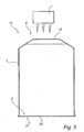
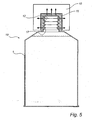
- FIGS. 2-5 illustrate schematically a second preferred inventive method for producing a container provided with a screw cap assembly.
- a method for producing a container provided with a screw cap assembly.
- the container may comprise a thermoformed body, which after filling with suitable contents is sealed by applying a sealing means over an open bottom side of the body. This sealing means then forms a bottom of the container.
- FIG. 1 illustrates the method for producing such a body 1 of a container (not shown), a screw cap assembly 2 being arranged on the body 1 in connection with the thermoforming thereof according to a first preferred embodiment of the present invention.
- the Figure shows how the body 1 is thermoformed at a thermoforming station 3 from a web-shaped material 4 in a roll. It will be appreciated that the web-shaped material 4 can be supplied in other ways, for instance by extrusion. The material can also be supplied in sheets.
- the web-shaped material 4 comprises a core layer, which in turn contains a filler of mineral material and a binder of polyolefin material.
- Preferred mineral materials are chalk, talc and/or mica. This allows production of inexpensive as well as environment-friendly containers which even at small wall thicknesses have the necessary rigidity.
- thermoformed body 1 is of an essentially cylindrical form, but it will be appreciated that the body 1 is preferably given a somewhat conical shape in order to facilitate the subsequent removal of the body 1 from the thermoforming station 3 .
- the body 1 further has an open bottom side 5 and a side 6 which is opposite to the bottom side 5 and at which the screw cap assembly 2 is arranged.
- the web-shaped material 4 is thus supplied to the thermoforming station 3 via a heating station 7 , at which the web-shaped material 4 is heated (which is indicated by means of flash-type arrows) up to a temperature that is required for thermoforming.
- the thermoforming station 3 comprises a forming means 8 with a cavity 9 and a thermoforming means 10 .
- the cavity 9 has an inner shape corresponding to the outer shape of the completed body 1 .
- a screw cap 11 with an internal thread 12 is inserted in the bottom 13 of the cavity 9 .
- the cavity 9 has in said bottom 13 a hole 14 , in which the screw cap 11 is arranged with its opening 15 directed towards the cavity 9 .
- the web-shaped material 4 is supplied in its heated state to the thermoforming station 3 in such manner that part thereof covers the cavity 9 of the forming means 8 .
- thermoforming means 10 is actuated for thermoforming of the body 1 .
- the thermoforming is carried out by a pneumatic forming operation, which is carried out by applying a pressure above atmospheric to the side 16 of the web-shaped material 4 facing away from the cavity 9 .
- a pressure above atmospheric to the side 16 of the web-shaped material 4 facing away from the cavity 9 .
- part of the web-shaped material 4 is pressed into the cavity 9 which is indicated by the arrow P 1 .
- the thermoforming can also be assisted by a stamping means (not shown) which mechanically moves the web-shaped material 4 into the cavity 9 .
- a heated wall portion 18 of the body 1 will be applied to and thus also cover the opening 15 of the screw cap 11 (indicated by means of dashed lines). Then the air will press the heated wall portion 18 into the screw cap 11 , the wall portion 18 assuming the shape of the externally threaded projection 17 . Said projection 17 will be sealed. It will be appreciated that the projection 17 can be open by a user in connection with the first opening of the completed container. Alternatively, it is possible to open the projection 17 in an operation immediately after thermoforming. For instance, it is possible to insert a means into the body 1 for punching a portion in the side of the projection 17 facing away from the body. This portion can later be removed or welded to the screw cap 11 .
- thermoformed body 1 can be released from the rest of the web-shaped material 4 in connection with the thermoforming thereof or in a subsequent operation.
- a body 1 provided with a screw cap assembly 2 is accomplished in an extremely simple manner.
- the body 1 can then be filled with contents to be finally sealed by applying a sealing means (not shown) over the open bottom side 5 of the body 1 .
- FIGS. 2-5 illustrate the method for producing a container 19 provided with a screw cap assembly 2 , the screw cap assembly 2 being arranged on the container 19 in its filled and sealed state according to a second preferred embodiment of the present invention.
- the container 19 comprises a thermoformed body 1 and a sealing means 20 applied over an open bottom side 5 of the body.
- the sealing means 20 consists of a wafer 21 , which is applied over said bottom side 5 after filling of the body with suitable contents, said wafer 21 forming a bottom 22 of the container 19 .
- the container 19 does not comprise a screw cap assembly 2 in its state immediately after filling and sealing.
- a wall portion 18 of the body 1 of the container 19 is first heated at a heating station 7 to a temperature as required for thermoforming, which is indicated in FIG. 3 by means of flash-type arrows.
- This wall portion 18 is according to the shown embodiment located at a side 6 opposite to the bottom side 5 of the body 1 . This side 6 thus forms the upper side of the container 19 while said wafer 21 forms the bottom 22 of the container 19 .
- FIG. 4 illustrates how an internally threaded screw cap 11 is applied to the container 19 with its opening 15 facing the heated wall portion 18 in such a manner that the opening 15 is covered by said wall portion 18 .
- the screw cap 11 has a number of through going suction ducts 23 .
- FIG. 5 shows how a thermoforming means 18 is applied round the screw cap 11 .
- the thermoforming means 10 is arranged for pneumatic thermoforming of an externally threaded projection 17 on the body 1 of the container 19 , the screw cap 11 acting as a mould.
- thermoforming means 10 is adapted to evacuate air from the interior of the screw cap 11 via said suction ducts 23 for generating a subatmospheric pressure, which sucks the heated wall portion 18 into the screw cap 11 .
- the wall portion 18 will be made to abut against the internal thread 12 of the screw cap 11 and then assume the shape of an externally threaded projection 17 .
- a method is thus provided, which allows simple and also inexpensive production of a container provided with a screw cap assembly.
- the assembly is applied more specifically to the container by heating of a wall portion of its body, to which wall portion a screw cap is later applied, after which an externally threaded projection is thermoformed on the container, the screw cap acting as a mould.
- the screw cap assembly can be applied to the container during production thereof or after it has been filled with contents and then sealed.
Landscapes
- Engineering & Computer Science (AREA)
- Mechanical Engineering (AREA)
- Manufacturing & Machinery (AREA)
- Blow-Moulding Or Thermoforming Of Plastics Or The Like (AREA)
- Closures For Containers (AREA)
- Containers Having Bodies Formed In One Piece (AREA)
- Auxiliary Devices For And Details Of Packaging Control (AREA)
Abstract
A method for producing a container (19) provided with a screw cap assembly. The method is characterised by the steps of arranging a screw cap (11) provided with an internal thread (12) relative to a heated wall portion (18) of a body (1) of the container (19) in such manner that an opening (15) of the screw cap (11) is applied to and thus covered by the wall portion (18), and thermo-forming in said wall portion (18) a projection (17) provided with an external thread, said screw cap (11) acting as a mould.
Description
- The present invention relates to a method for producing a container provided with a screw cap assembly.
- Containers of this type can be produced in a number of different ways, for instance by blow moulding or thermoforming.
- In particular it is possible to produce such containers of a material comprising a core layer with a filler of mineral material and a binder of polyolefin material. Such containers are advantageous, among other things since they are inexpensive to produce while they can be made to have a good rigidity even with a relatively small material thickness.
- In many cases it is advantageous to provide the container with an opening means in the form of a screw cap assembly. In the case with blow-moulded containers, this is relative easy to accomplish. The mould in which the container is blow moulded can, for instance, have a portion which forms an externally threaded projection of the container during the blow moulding process, to which projection a complementarily designed screw cap is connectable. If a screw cap assembly is required for a thermoformed container, it is, however, necessary for a separate screw cap assembly to be connected to the container in a suitable manner. This is a fairly complicated and expensive method, and therefore thermoformed containers usually have no screw cap assembly. It will be appreciated that containers comprising a screw cap assembly are advantageous since the containers will be resealable.
- There is thus a need for an improved method of producing thermoformed containers comprising a screw cap assembly.
- In view of the above, a first object of the present invention is to provide an improved method for producing a container provided with a screw cap assembly.
- A second object is to provide a method which in a cost-effective manner allows production of such containers.
- According to the present invention, these objects and also other objects that will be evident from the following description will be achieved by a method having the features stated in
claim 1. Preferred embodiments of the method are evident from claims 2-8. - More specifically, according to the present invention a method is provided for producing a container provided with a screw cap assembly, said method being characterised by the steps of arranging a screw cap provided with an internal thread relative to a heated wall portion of a body of the container in such manner that an opening of the screw cap is applied to and thus covered by the wall portion, and thermoforming in said wall portion a projection provided with an external thread, said screw cap acting as a mould.
- This results in a method which easily allows production of a container with a screw cap assembly. The container is provided with a screw cap assembly by thermoforming of an externally threaded projection in a heated wall portion of the container, a screw cap acting as a mould. A threaded projection, with which the screw cap engages, is thus provided in an extremely quick and simple manner.
- According to a preferred embodiment of the method, the step of thermoforming said projection is carried out integrally with the step of thermoforming the body of the container. The body of the container is preferably thermoformed in a forming means with a hole in which the screw cap is arranged. Advantageously the body of the container and the projection produced integrally therewith are thermoformed by a pneumatic forming operation, in which a heated web- or sheet-shaped body material is pressed by means of air into a forming means, whereby said air also presses said wall portion into the screw cap to form said projection.
- According to one more preferred embodiment of the inventive method, the step of thermoforming said projection is preceded by the steps of filling the body of the container with contents and sealing the body. Preferably the projection is thermoformed by a pneumatic forming operation, in which the heated wall portion is inserted into the screw cap to form said projection. This is advantageously achieved by evacuation of air from the screw cap via throughgoing suction ducts, whereby a sub-atmospheric pressure is generated in the screw cap and sucks the wall portion into the same.
- The body of the container is advantageously made of a material with a core layer comprising a filler of mineral material and a binder of polyolefin. The material of which the body of the container is made results in a container which is rigid even at a relatively small wall thickness.
- Preferred embodiments of the present invention will now be described by way of example and with reference to the accompanying drawings.
- FIG. 1 is a schematic view of a first preferred inventive method for producing a container provided with a screw cap assembly.
- FIGS. 2-5 illustrate schematically a second preferred inventive method for producing a container provided with a screw cap assembly.
- According to the present invention, a method is provided for producing a container provided with a screw cap assembly.
- The container may comprise a thermoformed body, which after filling with suitable contents is sealed by applying a sealing means over an open bottom side of the body. This sealing means then forms a bottom of the container. Subsequently some different preferred embodiments of the inventive method will be described with reference to containers of the type described above, equivalent components being given the same reference numerals. It will be appreciated, however, that the container can be designed in other manners.
- FIG. 1, to which reference is now made, illustrates the method for producing such a
body 1 of a container (not shown), ascrew cap assembly 2 being arranged on thebody 1 in connection with the thermoforming thereof according to a first preferred embodiment of the present invention. - The Figure shows how the
body 1 is thermoformed at athermoforming station 3 from a web-shaped material 4 in a roll. It will be appreciated that the web-shaped material 4 can be supplied in other ways, for instance by extrusion. The material can also be supplied in sheets. - The web-
shaped material 4 comprises a core layer, which in turn contains a filler of mineral material and a binder of polyolefin material. Preferred mineral materials are chalk, talc and/or mica. This allows production of inexpensive as well as environment-friendly containers which even at small wall thicknesses have the necessary rigidity. - The
thermoformed body 1 is of an essentially cylindrical form, but it will be appreciated that thebody 1 is preferably given a somewhat conical shape in order to facilitate the subsequent removal of thebody 1 from thethermoforming station 3. Thebody 1 further has anopen bottom side 5 and aside 6 which is opposite to thebottom side 5 and at which thescrew cap assembly 2 is arranged. - In order to produce said
body 1, the web-shaped material 4 is thus supplied to thethermoforming station 3 via aheating station 7, at which the web-shaped material 4 is heated (which is indicated by means of flash-type arrows) up to a temperature that is required for thermoforming. - The
thermoforming station 3 comprises a formingmeans 8 with acavity 9 and a thermoforming means 10. - The
cavity 9 has an inner shape corresponding to the outer shape of the completedbody 1. Ascrew cap 11 with aninternal thread 12 is inserted in thebottom 13 of thecavity 9. Thecavity 9 has in said bottom 13 ahole 14, in which thescrew cap 11 is arranged with itsopening 15 directed towards thecavity 9. - Thus the web-
shaped material 4 is supplied in its heated state to thethermoforming station 3 in such manner that part thereof covers thecavity 9 of the forming means 8. - Then the thermoforming means 10 is actuated for thermoforming of the
body 1. According to the shown embodiment, the thermoforming is carried out by a pneumatic forming operation, which is carried out by applying a pressure above atmospheric to theside 16 of the web-shaped material 4 facing away from thecavity 9. As a result, part of the web-shaped material 4 is pressed into thecavity 9 which is indicated by the arrow P1. It will be appreciated that the thermoforming can also be assisted by a stamping means (not shown) which mechanically moves the web-shaped material 4 into thecavity 9. - In connection with the thermoforming of the
body 1, an externally threadedprojection 17 of thebody 1 is simultaneously thermoformed, thescrew cap 11 acting as a mould, which is clearly to be seen in the broken-away enlargement of a detail in FIG. 1. - A
heated wall portion 18 of thebody 1 will be applied to and thus also cover the opening 15 of the screw cap 11 (indicated by means of dashed lines). Then the air will press theheated wall portion 18 into thescrew cap 11, thewall portion 18 assuming the shape of the externally threadedprojection 17. Saidprojection 17 will be sealed. It will be appreciated that theprojection 17 can be open by a user in connection with the first opening of the completed container. Alternatively, it is possible to open theprojection 17 in an operation immediately after thermoforming. For instance, it is possible to insert a means into thebody 1 for punching a portion in the side of theprojection 17 facing away from the body. This portion can later be removed or welded to thescrew cap 11. - The
thermoformed body 1 can be released from the rest of the web-shapedmaterial 4 in connection with the thermoforming thereof or in a subsequent operation. - Thus, a
body 1 provided with ascrew cap assembly 2 is accomplished in an extremely simple manner. As mentioned above, thebody 1 can then be filled with contents to be finally sealed by applying a sealing means (not shown) over the openbottom side 5 of thebody 1. - FIGS. 2-5, to which reference is now made, illustrate the method for producing a
container 19 provided with ascrew cap assembly 2, thescrew cap assembly 2 being arranged on thecontainer 19 in its filled and sealed state according to a second preferred embodiment of the present invention. - The
container 19 comprises athermoformed body 1 and a sealing means 20 applied over an openbottom side 5 of the body. - The sealing means 20 consists of a
wafer 21, which is applied over saidbottom side 5 after filling of the body with suitable contents, saidwafer 21 forming a bottom 22 of thecontainer 19. - As is evident form FIG. 2, the
container 19 does not comprise ascrew cap assembly 2 in its state immediately after filling and sealing. - In order to provide the
container 19 with such ascrew cap assembly 2, awall portion 18 of thebody 1 of thecontainer 19 is first heated at aheating station 7 to a temperature as required for thermoforming, which is indicated in FIG. 3 by means of flash-type arrows. Thiswall portion 18 is according to the shown embodiment located at aside 6 opposite to thebottom side 5 of thebody 1. Thisside 6 thus forms the upper side of thecontainer 19 while saidwafer 21 forms the bottom 22 of thecontainer 19. - FIG. 4 illustrates how an internally threaded
screw cap 11 is applied to thecontainer 19 with itsopening 15 facing theheated wall portion 18 in such a manner that theopening 15 is covered by saidwall portion 18. As is evident from the Figure, thescrew cap 11 has a number of through goingsuction ducts 23. - FIG. 5 shows how a thermoforming means 18 is applied round the
screw cap 11. The thermoforming means 10 is arranged for pneumatic thermoforming of an externally threadedprojection 17 on thebody 1 of thecontainer 19, thescrew cap 11 acting as a mould. - The thermoforming means 10 is adapted to evacuate air from the interior of the
screw cap 11 via saidsuction ducts 23 for generating a subatmospheric pressure, which sucks theheated wall portion 18 into thescrew cap 11. Thewall portion 18 will be made to abut against theinternal thread 12 of thescrew cap 11 and then assume the shape of an externally threadedprojection 17. - The
throughgoing suction ducts 23 of thescrew cap 11 are advantageously sealed in a subsequent operation. - The above described second preferred embodiment of the inventive method for producing a
container 19 provided with ascrew cap assembly 2 thus allows application of thescrew cap assembly 2 to thecontainer 19 when this has already been filled and sealed. It should be noted that the seal of thecontainer 19 is not broken when applying thescrew cap assembly 2. - According to the present invention, a method is thus provided, which allows simple and also inexpensive production of a container provided with a screw cap assembly. The assembly is applied more specifically to the container by heating of a wall portion of its body, to which wall portion a screw cap is later applied, after which an externally threaded projection is thermoformed on the container, the screw cap acting as a mould. The screw cap assembly can be applied to the container during production thereof or after it has been filled with contents and then sealed.
- It will be appreciated that the present invention is not restricted to the embodiments described. Several variants and modifications are feasible, which means that the scope of the invention is exclusively defined by the appended claims.
Claims (7)
1. A method for producing a container (19) provided with a screw cap assembly,
characterised by the steps of
arranging a screw cap (11) provided with an internal thread (12) relative to a heated wall portion (18) of a body (1) of the container in such manner that an opening (15) of the screw cap (11) is applied to and thus covered by the wall portion (18), and
thermoforming in said wall portion (18) a projection (17) provided with an external thread, said screw cap (11) acting as a mould,
wherein the step of thermoforming said projection (17) is carried out integrally with the step of thermoforming the body (1) of the container (19).
2. A method as claimed in claim 1 , wherein the step of thermoforming the body (1) is carried out in a forming means (8) with a hole (14), in which said screw cap (11) is arranged.
3. A method as claimed in claim 1 or 2, wherein the body (1) and the projection (17) which is produced integrally therewith are thermoformed by a pneumatic forming operation, in which a heated web- or sheet-shaped body material (4) is pressed by means of air into a forming means (8), whereby said air also presses said wall portion (18) into the screw cap (11) to form said projection (17).
4. A method for producing a container (19) provided with a screw cap assembly,
characterised by the steps of
arranging a screw cap (11) provided with an internal thread (12) relative to a heated wall portion (18) of a body (1) of the container in such manner that an opening (15) of the screw cap (11) is applied to and thus covered by the wall portion (18), and
thermoforming in said wall portion (18) a projection (17) provided with an external thread, said screw cap (11) acting as a mould,
wherein the step of thermoforming said projection (17) is preceded by the steps of filling the body (1) of the container (19) with contents and sealing the container (19).
5. A method as claimed in claim 4 , wherein the projection (17) is thermoformed by a pneumatic forming operation, in which the heated wall portion (18) is inserted into the screw cap (11) to form said projection (17).
6. A method as claimed in claim 5 , wherein the heated wall portion (18) is inserted into the screw cap (11) by evacuation of air from the screw cap (11) via throughgoing suction ducts (23), whereby a subatmospheric pressure is generated in the screw cap (11) and sucks the wall portion (18) into the same.
7. A method as claimed in claim 1 , wherein said body (1) is made of a material (4) having a core layer comprising a filler of mineral material and a binder of polyolefin.
Applications Claiming Priority (3)
| Application Number | Priority Date | Filing Date | Title |
|---|---|---|---|
| SE0102788-7 | 2001-08-22 | ||
| SE0102788A SE519498C2 (en) | 2001-08-22 | 2001-08-22 | Method for making a package provided with a screw cap arrangement |
| PCT/SE2002/001500 WO2003041942A1 (en) | 2001-08-22 | 2002-08-21 | Method for producing a container provided with a screw cap assembly |
Publications (1)
| Publication Number | Publication Date |
|---|---|
| US20040207128A1 true US20040207128A1 (en) | 2004-10-21 |
Family
ID=20285086
Family Applications (1)
| Application Number | Title | Priority Date | Filing Date |
|---|---|---|---|
| US10/482,964 Abandoned US20040207128A1 (en) | 2001-08-22 | 2002-08-21 | Method for producing a container provided with a screw cap assembly |
Country Status (13)
| Country | Link |
|---|---|
| US (1) | US20040207128A1 (en) |
| EP (1) | EP1419045A1 (en) |
| JP (1) | JP2005508773A (en) |
| KR (1) | KR20040041582A (en) |
| CN (1) | CN1538903A (en) |
| AU (1) | AU2002325455B2 (en) |
| BR (1) | BR0211904A (en) |
| CA (1) | CA2455678A1 (en) |
| PL (1) | PL367899A1 (en) |
| RU (1) | RU2004108135A (en) |
| SE (1) | SE519498C2 (en) |
| TW (1) | TW577839B (en) |
| WO (1) | WO2003041942A1 (en) |
Cited By (1)
| Publication number | Priority date | Publication date | Assignee | Title |
|---|---|---|---|---|
| EP4342654A1 (en) * | 2022-08-11 | 2024-03-27 | BBS Corporation | Crystal clear high barrier thermoformed plastic bottle |
Citations (8)
| Publication number | Priority date | Publication date | Assignee | Title |
|---|---|---|---|---|
| US3341644A (en) * | 1959-07-29 | 1967-09-12 | Flair Plastics Corp | Process for producing plastic containers |
| US3690088A (en) * | 1970-09-08 | 1972-09-12 | Dave Chapman | Method of packaging |
| US4671721A (en) * | 1984-03-12 | 1987-06-09 | Rodger Pratt | Apparatus and method for positioning an object in a building |
| US4844270A (en) * | 1988-06-13 | 1989-07-04 | Rampart Packaging Inc. | Screw cap jar |
| US5281387A (en) * | 1992-07-07 | 1994-01-25 | Continental Pet Technologies, Inc. | Method of forming a container having a low crystallinity |
| US5705112A (en) * | 1989-07-14 | 1998-01-06 | Gram; Jes Tougaard | Procedure for the production of an assembled object |
| US6129880A (en) * | 1998-11-25 | 2000-10-10 | Thatcher Tubes Llc | Method of forming a headed thermoplastic tube with a reusable closure in a single step |
| US6726873B1 (en) * | 1997-12-23 | 2004-04-27 | Coraltech Limited | Thermoforming or blow moulding of injection moulded preforms |
Family Cites Families (3)
| Publication number | Priority date | Publication date | Assignee | Title |
|---|---|---|---|---|
| EP0240037B1 (en) * | 1983-11-22 | 1993-09-08 | Yoshino Kogyosho Co., Ltd. | Blow-molded bottle-shaped container of biaxially orientated thermoplastic synthetic resin with wide port and method of molding the same |
| US4671421A (en) * | 1986-03-06 | 1987-06-09 | Owens-Illinois, Inc. | Plastic container |
| ES2178904B1 (en) * | 1999-07-12 | 2004-04-01 | Cebal Entec, S.A. | PERFECTED CROWN-PLUG SYSTEM FOR ALUMINUM AND / OR STEEL BOTTLES. |
-
2001
- 2001-08-22 SE SE0102788A patent/SE519498C2/en not_active IP Right Cessation
- 2001-12-13 TW TW090130926A patent/TW577839B/en active
-
2002
- 2002-08-21 CA CA002455678A patent/CA2455678A1/en not_active Abandoned
- 2002-08-21 EP EP02759041A patent/EP1419045A1/en not_active Withdrawn
- 2002-08-21 BR BR0211904-8A patent/BR0211904A/en not_active Application Discontinuation
- 2002-08-21 CN CNA02815391XA patent/CN1538903A/en active Pending
- 2002-08-21 RU RU2004108135/12A patent/RU2004108135A/en not_active Application Discontinuation
- 2002-08-21 WO PCT/SE2002/001500 patent/WO2003041942A1/en not_active Ceased
- 2002-08-21 JP JP2003543805A patent/JP2005508773A/en not_active Withdrawn
- 2002-08-21 US US10/482,964 patent/US20040207128A1/en not_active Abandoned
- 2002-08-21 KR KR10-2004-7002579A patent/KR20040041582A/en not_active Withdrawn
- 2002-08-21 AU AU2002325455A patent/AU2002325455B2/en not_active Expired - Fee Related
- 2002-08-21 PL PL02367899A patent/PL367899A1/en unknown
Patent Citations (8)
| Publication number | Priority date | Publication date | Assignee | Title |
|---|---|---|---|---|
| US3341644A (en) * | 1959-07-29 | 1967-09-12 | Flair Plastics Corp | Process for producing plastic containers |
| US3690088A (en) * | 1970-09-08 | 1972-09-12 | Dave Chapman | Method of packaging |
| US4671721A (en) * | 1984-03-12 | 1987-06-09 | Rodger Pratt | Apparatus and method for positioning an object in a building |
| US4844270A (en) * | 1988-06-13 | 1989-07-04 | Rampart Packaging Inc. | Screw cap jar |
| US5705112A (en) * | 1989-07-14 | 1998-01-06 | Gram; Jes Tougaard | Procedure for the production of an assembled object |
| US5281387A (en) * | 1992-07-07 | 1994-01-25 | Continental Pet Technologies, Inc. | Method of forming a container having a low crystallinity |
| US6726873B1 (en) * | 1997-12-23 | 2004-04-27 | Coraltech Limited | Thermoforming or blow moulding of injection moulded preforms |
| US6129880A (en) * | 1998-11-25 | 2000-10-10 | Thatcher Tubes Llc | Method of forming a headed thermoplastic tube with a reusable closure in a single step |
Cited By (1)
| Publication number | Priority date | Publication date | Assignee | Title |
|---|---|---|---|---|
| EP4342654A1 (en) * | 2022-08-11 | 2024-03-27 | BBS Corporation | Crystal clear high barrier thermoformed plastic bottle |
Also Published As
| Publication number | Publication date |
|---|---|
| AU2002325455B2 (en) | 2004-09-30 |
| JP2005508773A (en) | 2005-04-07 |
| CA2455678A1 (en) | 2003-05-22 |
| EP1419045A1 (en) | 2004-05-19 |
| CN1538903A (en) | 2004-10-20 |
| TW577839B (en) | 2004-03-01 |
| RU2004108135A (en) | 2004-12-27 |
| SE0102788L (en) | 2003-02-23 |
| BR0211904A (en) | 2004-09-21 |
| PL367899A1 (en) | 2005-03-07 |
| SE519498C2 (en) | 2003-03-04 |
| WO2003041942A1 (en) | 2003-05-22 |
| KR20040041582A (en) | 2004-05-17 |
| SE0102788D0 (en) | 2001-08-22 |
Similar Documents
| Publication | Publication Date | Title |
|---|---|---|
| US5819507A (en) | Method of filling a packaging container | |
| CA2463853C (en) | Container, thermo-molding apparatus and method for thermo-molding the same | |
| US5043130A (en) | Method of manufacturing labeled containers | |
| RU2471628C2 (en) | Making package and package | |
| US20220064869A1 (en) | Lid, method of producing lid, and molds for forming molded pulp | |
| US3235639A (en) | Solid flanged thermoplastic articles and apparatus and method for making the same | |
| EP0796199A1 (en) | Method of filling a packaging container | |
| JP3989024B2 (en) | Method and mold for injection molding plastic material parts into packaging sheet material | |
| AU2002325455B2 (en) | Method for producing a container provided with a screw cap assembly | |
| AU2002325455A1 (en) | Method for producing a container provided with a screw cap assembly | |
| JP2845944B2 (en) | Method for producing barrier thin molded article and barrier thin molded article | |
| EP1147990A3 (en) | Bottle of thermoplastic material and method for the manufacture and filing of same | |
| JP2003160119A (en) | Manufacturing method of deep drawn paper container | |
| JP7379865B2 (en) | Composite container and its manufacturing method | |
| US20040238548A1 (en) | Container and method for manufacturing thereof | |
| JP4678804B2 (en) | Paper packaging container and molding method and apparatus thereof | |
| JPH05253965A (en) | Multilayered thin-walled container and production thereof | |
| JP3260926B2 (en) | Tube container manufacturing method | |
| JPH10119951A (en) | Manufacturing method of composite container | |
| EP1080870A2 (en) | Method for forming a hermetic flange seal in a blow-molded plastic container | |
| JP2001080677A (en) | Composite container | |
| JPH046890Y2 (en) | ||
| JPS5813336B2 (en) | Youkino Seizouhouhou | |
| JPH06239364A (en) | Compound container and manufacture thereof | |
| JP2803878B2 (en) | Composite container and method for producing the same |
Legal Events
| Date | Code | Title | Description |
|---|---|---|---|
| AS | Assignment |
Owner name: ECO LEAN RESEARCH & DEVELOPMENT, DENMARK Free format text: ASSIGNMENT OF ASSIGNORS INTEREST;ASSIGNOR:ROSEN, AKE;REEL/FRAME:015077/0114 Effective date: 20040205 |
|
| STCB | Information on status: application discontinuation |
Free format text: ABANDONED -- FAILURE TO RESPOND TO AN OFFICE ACTION |