US20040189321A1 - Fiber optic MT ferrule connector - Google Patents
Fiber optic MT ferrule connector Download PDFInfo
- Publication number
- US20040189321A1 US20040189321A1 US10/397,464 US39746403A US2004189321A1 US 20040189321 A1 US20040189321 A1 US 20040189321A1 US 39746403 A US39746403 A US 39746403A US 2004189321 A1 US2004189321 A1 US 2004189321A1
- Authority
- US
- United States
- Prior art keywords
- holding
- alignment
- elements
- fixture
- connector component
- Prior art date
- Legal status (The legal status is an assumption and is not a legal conclusion. Google has not performed a legal analysis and makes no representation as to the accuracy of the status listed.)
- Abandoned
Links
- 239000000835 fiber Substances 0.000 title description 4
- 230000003287 optical effect Effects 0.000 claims description 21
- 238000003780 insertion Methods 0.000 description 2
- 230000037431 insertion Effects 0.000 description 2
- 230000000712 assembly Effects 0.000 description 1
- 238000000429 assembly Methods 0.000 description 1
- 230000008878 coupling Effects 0.000 description 1
- 238000010168 coupling process Methods 0.000 description 1
- 238000005859 coupling reaction Methods 0.000 description 1
- 230000002950 deficient Effects 0.000 description 1
- 239000002184 metal Substances 0.000 description 1
Images

Classifications
-
- G—PHYSICS
- G02—OPTICS
- G02B—OPTICAL ELEMENTS, SYSTEMS OR APPARATUS
- G02B6/00—Light guides; Structural details of arrangements comprising light guides and other optical elements, e.g. couplings
- G02B6/24—Coupling light guides
- G02B6/36—Mechanical coupling means
- G02B6/38—Mechanical coupling means having fibre to fibre mating means
- G02B6/3807—Dismountable connectors, i.e. comprising plugs
-
- B—PERFORMING OPERATIONS; TRANSPORTING
- B24—GRINDING; POLISHING
- B24B—MACHINES, DEVICES, OR PROCESSES FOR GRINDING OR POLISHING; DRESSING OR CONDITIONING OF ABRADING SURFACES; FEEDING OF GRINDING, POLISHING, OR LAPPING AGENTS
- B24B19/00—Single-purpose machines or devices for particular grinding operations not covered by any other main group
- B24B19/22—Single-purpose machines or devices for particular grinding operations not covered by any other main group characterised by a special design with respect to properties of the material of non-metallic articles to be ground
- B24B19/226—Single-purpose machines or devices for particular grinding operations not covered by any other main group characterised by a special design with respect to properties of the material of non-metallic articles to be ground of the ends of optical fibres
-
- B—PERFORMING OPERATIONS; TRANSPORTING
- B24—GRINDING; POLISHING
- B24B—MACHINES, DEVICES, OR PROCESSES FOR GRINDING OR POLISHING; DRESSING OR CONDITIONING OF ABRADING SURFACES; FEEDING OF GRINDING, POLISHING, OR LAPPING AGENTS
- B24B41/00—Component parts such as frames, beds, carriages, headstocks
- B24B41/06—Work supports, e.g. adjustable steadies
Definitions
- This invention is related to assemblies that allow for the testing of optical connector components in a reliable, safe manner prior to final assembly of optical connectors into a system. More particularly, the invention relates to a fixture that temporarily holds the optical components so they may be easily assembled and removed during testing.
- optical connector components for example MT ferrules
- spring clips such as the clip 2 shown in prior art FIG. 1 which is supplied by USConec.
- the legs 4 and 6 are spread apart and each leg is forced over the side of one of the ferrules that is remote from the fiber connection of each ferrule.
- This arrangement results in slow and awkward assembly and removal of the connectors. It is also susceptible to causing damage to the optical components.
- the present invention provides a fixture that allows for the temporary testing of optical connector components in a reliable, efficient manner.
- a fixture for temporarily holding a pair of optical MT ferrules in alignment for testing purposes is constructed with three holding elements each having a holding cavity. Two of these cavities conform to the shape of one connector component of the optical connector, and the other of which conforms to the shape of the other connector component.
- the holding elements. are aligned with alignment pins and corresponding alignment bores.
- the two holding elements that conform to the shape of one connector component are secured together by a pair of fastening elements, and one of these two holding elements is secured to the third holding element by at least one fastening element.
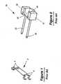
- FIG. 1 is a side view of a prior art clip that is used to hold two optical MT ferrules
- FIG. 2 is a perspective view of a prior art pin assembly for aligning two optical ferrules
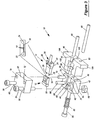
- FIG. 3 is an exploded perspective view of the fixture of the present invention.
- the invention provides a fixture that allows for fast, reliable connections between fiber optical connectors which is especially useful for the testing of optical connectors, such as the common MT type of optical connector.
- the fixture enables MT ferrules to be temporarily connected prior to assembly of them in connectors for their final application. After optical connectors have been assembled they can be very difficult to repair if one of them is defective.
- MT ferrules for example, do not form a complete connector but they can be easily mated to another MT ferrule for testing.
- MT optical ferrules have been tested previously by temporarily coupling two ferrules together with simple metal spring clips, as shown in prior art FIG. 1, that merely clip on the ends of each of the ferrules and force them together.
- USConec Ltd. of Hickory, N.C. sells optical ferrules and spring clips for this purpose. While these spring clips can be used for functional testing they are not easily installed or removed. The ferrules are not held in a fixed mounting by the spring clip and this increases the possibility of damage during testing unless a special mounting is also provided.
- the present invention allows for easy insertion and removal of the ferrules in the fixture and also protects them against damage during testing.
- FIG. 3 shows a fixture 10 constructed in accordance with the invention to hold the two ferrules 12 and 14 that are to be mated together.
- the ferrule 12 has a front face 16 that has a number of optical ports 18 that are aligned with a corresponding number of optical ports, (not shown), in the front face 20 of the ferrule 14 .
- the ferrule 12 has a pair of alignment holes 22 , 24 that respectively receive the pins 26 , 28 that are associated with the ferrule 14 .
- the pins 26 , 28 are part of a pin assembly 30 , (shown in FIG. 2),that has a body 32 into which the pins 26 , 28 are secured.
- the prior art pin assembly has two wings 34 , 36 and a recessed center portion 38 that allows the assembly to be slipped onto the ferrule 14 to allow the two ferrules to be coupled together.
- the spring clip 40 was in the past then clipped onto the rear surfaces of the ferrules 12 , 14 to hold them together. This assembly was then held in place with the aid of a clamping tool.
- the invention replaces the spring clip 20 to provide for easier insertion and removal and more protection during testing by placing the ferrules 12 , 14 into the fixture 10 .
- the fixture 10 consists of a first block 42 that has a cavity 44 that is shaped to receive the ferrule 12 .
- the block 42 has an elongated recess 48 which receives the body of the ferrule 12 and a deeper cross-wise recess 48 that receives the rim 50 of the ferrule 12 .
- An upper block 52 fits over the top of the ferrule 12 and it has elongated and cross-wise recesses that are matched to the corresponding recesses in block 42 .
- the blocks 42 and 52 are secured together by the bolts 54 , 56 which pass through the holes 58 , 60 , respectively, in block 52 and the holes 62 , 69 , respectively, in block 42 .
- the bolts are screwed into threaded fasteners, such as the nut 66 .
- Guide pin 68 is inserted into the hole 72 in block 42 and the hole 72 in block 52
- guide pin 70 is inserted into the hole 76 in block 42 and the hole 78 in block 52 .
- a bolt 80 is inserted axially into a coil spring 82 and into a hole 84 that runs through the block 42 .
- Another block 86 is provided which receives the ferrule 14 .
- This block receives two alignment pins 88 , 90 that extend through holes 92 , 94 , respectively, in block 86 that are press fit into the holes 96 , 98 when block 86 is pushed into engagement with block 42 .
- the hole 100 in block 86 is threaded and allows for the bolt 80 to be screwed into it while compressing the spring 82 to provide a return force upon release.
- the block 86 has a recess 102 to receive the body of the ferrule 14 and the pin assembly 30 .
- the lips 104 , 106 provide surfaces that can be used to push the block 86 toward and away from the block 42 .
Landscapes
- Engineering & Computer Science (AREA)
- Mechanical Engineering (AREA)
- Physics & Mathematics (AREA)
- General Physics & Mathematics (AREA)
- Optics & Photonics (AREA)
- Mechanical Coupling Of Light Guides (AREA)
Abstract
Two connector components, such as MT ferrules are secured in a three part holding device for testing purposes. One of the connector components is located in cavities formed in two of the parts of the holding device and the other connector component is located in a cavity formed in the third part of the holding device. Fasteners hold the three pieces together and alignment between the pieces is provided by pin and bore provisions.
Description
- Not applicable.
- Not applicable.
- Not applicable.
- 1. Technical Field
- This invention is related to assemblies that allow for the testing of optical connector components in a reliable, safe manner prior to final assembly of optical connectors into a system. More particularly, the invention relates to a fixture that temporarily holds the optical components so they may be easily assembled and removed during testing.
- 2. Background Information
- As the use of fiber optical systems expands, the need for testing optical connections also increases. Currently optical connector components, for example MT ferrules, are couple together by spring clips, such as the
clip 2 shown in prior art FIG. 1 which is supplied by USConec. Thelegs 4 and 6 are spread apart and each leg is forced over the side of one of the ferrules that is remote from the fiber connection of each ferrule. This arrangement results in slow and awkward assembly and removal of the connectors. It is also susceptible to causing damage to the optical components. The present invention provides a fixture that allows for the temporary testing of optical connector components in a reliable, efficient manner. - A fixture for temporarily holding a pair of optical MT ferrules in alignment for testing purposes is constructed with three holding elements each having a holding cavity. Two of these cavities conform to the shape of one connector component of the optical connector, and the other of which conforms to the shape of the other connector component. The holding elements. are aligned with alignment pins and corresponding alignment bores. The two holding elements that conform to the shape of one connector component are secured together by a pair of fastening elements, and one of these two holding elements is secured to the third holding element by at least one fastening element.
- The invention is described by reference to the drawings in which:
- FIG. 1 is a side view of a prior art clip that is used to hold two optical MT ferrules,
- FIG. 2 is a perspective view of a prior art pin assembly for aligning two optical ferrules, and
- FIG. 3 is an exploded perspective view of the fixture of the present invention.
- The invention provides a fixture that allows for fast, reliable connections between fiber optical connectors which is especially useful for the testing of optical connectors, such as the common MT type of optical connector. The fixture enables MT ferrules to be temporarily connected prior to assembly of them in connectors for their final application. After optical connectors have been assembled they can be very difficult to repair if one of them is defective. However, MT ferrules, for example, do not form a complete connector but they can be easily mated to another MT ferrule for testing.
- MT optical ferrules have been tested previously by temporarily coupling two ferrules together with simple metal spring clips, as shown in prior art FIG. 1, that merely clip on the ends of each of the ferrules and force them together. USConec Ltd. of Hickory, N.C. sells optical ferrules and spring clips for this purpose. While these spring clips can be used for functional testing they are not easily installed or removed. The ferrules are not held in a fixed mounting by the spring clip and this increases the possibility of damage during testing unless a special mounting is also provided. The present invention allows for easy insertion and removal of the ferrules in the fixture and also protects them against damage during testing.
- FIG. 3 shows a
fixture 10 constructed in accordance with the invention to hold the twoferrules ferrule 12 has afront face 16 that has a number ofoptical ports 18 that are aligned with a corresponding number of optical ports, (not shown), in the front face 20 of theferrule 14. Theferrule 12 has a pair ofalignment holes pins ferrule 14. Thepins pin assembly 30, (shown in FIG. 2),that has abody 32 into which thepins wings recessed center portion 38 that allows the assembly to be slipped onto theferrule 14 to allow the two ferrules to be coupled together. The spring clip 40 was in the past then clipped onto the rear surfaces of theferrules - The invention replaces the spring clip 20 to provide for easier insertion and removal and more protection during testing by placing the
ferrules fixture 10. Thefixture 10 consists of afirst block 42 that has acavity 44 that is shaped to receive theferrule 12. Theblock 42 has anelongated recess 48 which receives the body of theferrule 12 and a deeper cross-wise recess 48 that receives therim 50 of theferrule 12. Anupper block 52 fits over the top of theferrule 12 and it has elongated and cross-wise recesses that are matched to the corresponding recesses inblock 42. - The
blocks bolts holes block 52 and theholes block 42. The bolts are screwed into threaded fasteners, such as thenut 66.Guide pin 68 is inserted into the hole72 inblock 42 and the hole72 inblock 52, whileguide pin 70 is inserted into the hole76 inblock 42 and the hole78 inblock 52. Abolt 80 is inserted axially into acoil spring 82 and into ahole 84 that runs through theblock 42. - Another
block 86 is provided which receives theferrule 14. This block receives twoalignment pins holes block 86 that are press fit into theholes block 86 is pushed into engagement withblock 42. Thehole 100 inblock 86 is threaded and allows for thebolt 80 to be screwed into it while compressing thespring 82 to provide a return force upon release. Theblock 86 has arecess 102 to receive the body of theferrule 14 and thepin assembly 30. Thelips block 86 toward and away from theblock 42.
Claims (5)
1. A fixture for holding first and second connector components in coupled alignment, comprising;
(a) a first holding element comprising a first holding cavity that conforms to at least a portion of the shape of said first connector component wherein said first holding cavity receives said first connector component therein,
(b) a second holding element comprising a second holding cavity that conforms to at least a portion of the shape of said second connector component wherein said second holding cavity receives said second connector component therein,
(c) a third holding element comprising a third holding cavity that conforms to at least a portion of the shape of said second connector component that is not received by said second holding element wherein said first and second cavities substantially encompass said second connector component,
(d) a pair of first and second fastening elements coupled to said second and third elements for securing said second and third holding elements together, and
(e) at least one third fastening element coupled to one of said second and third holding elements and to said first holding element for securing said one of said second and third holding elements and said first holding element together.
2). A fixture as claimed in claim 1 , comprising; at least one pair of alignment pins and matching alignment bores, wherein each of said alignment bores receives one of said alignment pins, and each of said alignment bores is located in one of said holding elements.
3). A fixture as claimed in claim 1 , comprising; at least one pair of alignment pins and matching alignment bores, wherein each of said alignment bores receives one of said alignment pins, and each of said alignment bores is located in one of said second or third holding elements or in said first holding element.
4). A fixture as claimed in claim 1 wherein said connector components consist of a pair of optical MT ferrules.
5). A fixture as claimed in claim 1 wherein said at least one of said third fastening elements comprises a threaded bore in said first holding element, a second bore in one of said second and third holding elements, a threaded screw having a shaft with threads thereon which extend through said second bore and are screwed into said threaded bore and a head thereon, and a coil spring that surrounds said shaft and is positioned between said head of said threaded screw and one of said. second and third holding elements that has said second bore therein.
Priority Applications (1)
| Application Number | Priority Date | Filing Date | Title |
|---|---|---|---|
| US10/397,464 US20040189321A1 (en) | 2003-03-26 | 2003-03-26 | Fiber optic MT ferrule connector |
Applications Claiming Priority (1)
| Application Number | Priority Date | Filing Date | Title |
|---|---|---|---|
| US10/397,464 US20040189321A1 (en) | 2003-03-26 | 2003-03-26 | Fiber optic MT ferrule connector |
Publications (1)
| Publication Number | Publication Date |
|---|---|
| US20040189321A1 true US20040189321A1 (en) | 2004-09-30 |
Family
ID=32989001
Family Applications (1)
| Application Number | Title | Priority Date | Filing Date |
|---|---|---|---|
| US10/397,464 Abandoned US20040189321A1 (en) | 2003-03-26 | 2003-03-26 | Fiber optic MT ferrule connector |
Country Status (1)
| Country | Link |
|---|---|
| US (1) | US20040189321A1 (en) |
Cited By (8)
| Publication number | Priority date | Publication date | Assignee | Title |
|---|---|---|---|---|
| KR101331829B1 (en) | 2013-04-12 | 2013-11-22 | 성결대학교 산학협력단 | Apparatus and method for auto testing endurance of optical connector and optical adaptor |
| WO2014121034A1 (en) | 2013-02-01 | 2014-08-07 | Commscope, Inc. Of North Carolina | Transitioning multi-core fiber to plural single core fibers |
| US9151923B2 (en) | 2013-02-05 | 2015-10-06 | Commscope, Inc. Of North Carolina | Methods of connectorizing multi-core fiber optic cables and related apparatus |
| US20150331210A1 (en) * | 2013-12-30 | 2015-11-19 | Avago Technologies General Ip (Singapore) Pte. Ltd. | Optical fiber cable assembly with low radiated emission coupling |
| US9250395B2 (en) | 2013-06-13 | 2016-02-02 | Commscope, Inc. Of North Carolina | Connector for multiple core optical fiber |
| US20160266328A1 (en) * | 2013-03-28 | 2016-09-15 | Ofs Fitel, Llc | Apparatus for Alignment of a Multicore Fiber in a Multifiber Connector and Method of Using Same |
| US9664863B2 (en) | 2013-01-08 | 2017-05-30 | Commscope, Inc. Of North Carolina | Selective UV curing of epoxy adjacent to optical fibers by transmitting UV energy through the fiber cladding |
| US20200096707A1 (en) * | 2018-09-20 | 2020-03-26 | Senko Advanced Components Inc | Stackable adapter housing for opposing mt ferrules |
Citations (5)
| Publication number | Priority date | Publication date | Assignee | Title |
|---|---|---|---|---|
| US5179028A (en) * | 1990-04-20 | 1993-01-12 | Hughes Aircraft Company | Antibody coated crystal chemical sensor |
| US5522980A (en) * | 1994-03-24 | 1996-06-04 | Pima Sensors, Inc. | Gas sensor and sensing device |
| US5712938A (en) * | 1996-05-30 | 1998-01-27 | Tai Jin Mold Mfg. Co. | Optical fiber connector |
| US6007256A (en) * | 1996-09-24 | 1999-12-28 | Sumitomo Wiring Systems, Ltd. | Optical connector that reduces the number of components used, that facilitates assembly, and that prevents spontaneous disassembly, and structure for attaching a boot to an optical connector |
| US6513989B1 (en) * | 1997-06-24 | 2003-02-04 | Tyco Electronics Logistics Ag | Ferrule container for holding a multiple optical fiber disposed in a ferrule, and a connector for connecting multiple optical fibers |
-
2003
- 2003-03-26 US US10/397,464 patent/US20040189321A1/en not_active Abandoned
Patent Citations (5)
| Publication number | Priority date | Publication date | Assignee | Title |
|---|---|---|---|---|
| US5179028A (en) * | 1990-04-20 | 1993-01-12 | Hughes Aircraft Company | Antibody coated crystal chemical sensor |
| US5522980A (en) * | 1994-03-24 | 1996-06-04 | Pima Sensors, Inc. | Gas sensor and sensing device |
| US5712938A (en) * | 1996-05-30 | 1998-01-27 | Tai Jin Mold Mfg. Co. | Optical fiber connector |
| US6007256A (en) * | 1996-09-24 | 1999-12-28 | Sumitomo Wiring Systems, Ltd. | Optical connector that reduces the number of components used, that facilitates assembly, and that prevents spontaneous disassembly, and structure for attaching a boot to an optical connector |
| US6513989B1 (en) * | 1997-06-24 | 2003-02-04 | Tyco Electronics Logistics Ag | Ferrule container for holding a multiple optical fiber disposed in a ferrule, and a connector for connecting multiple optical fibers |
Cited By (18)
| Publication number | Priority date | Publication date | Assignee | Title |
|---|---|---|---|---|
| US10908363B2 (en) | 2013-01-08 | 2021-02-02 | Commscope, Inc. Of North Carolina | Selective UV curing of epoxy adjacent to optical fibers by transmitting UV energy through the fiber cladding |
| US9664863B2 (en) | 2013-01-08 | 2017-05-30 | Commscope, Inc. Of North Carolina | Selective UV curing of epoxy adjacent to optical fibers by transmitting UV energy through the fiber cladding |
| US10317629B2 (en) * | 2013-02-01 | 2019-06-11 | Commscope, Inc. Of North Carolina | Connector for transitioning multi-core fiber to plural single core fibers |
| WO2014121034A1 (en) | 2013-02-01 | 2014-08-07 | Commscope, Inc. Of North Carolina | Transitioning multi-core fiber to plural single core fibers |
| US9429721B2 (en) | 2013-02-01 | 2016-08-30 | Commscope, Inc. Of North Carolina | Connector for transitioning multi-core fiber to plural single core fibers |
| US9995885B2 (en) | 2013-02-01 | 2018-06-12 | Commscope, Inc. Of North Carolina | Connector for transitioning multi-core fiber to plural single core fibers |
| US10823918B2 (en) | 2013-02-01 | 2020-11-03 | Commscope, Inc. Of North Carolina | Transitioning multi-core fiber to plural single core fibers |
| US9151923B2 (en) | 2013-02-05 | 2015-10-06 | Commscope, Inc. Of North Carolina | Methods of connectorizing multi-core fiber optic cables and related apparatus |
| US20160266328A1 (en) * | 2013-03-28 | 2016-09-15 | Ofs Fitel, Llc | Apparatus for Alignment of a Multicore Fiber in a Multifiber Connector and Method of Using Same |
| US9568684B2 (en) * | 2013-03-28 | 2017-02-14 | Ofs Fitel, Llc | Apparatus for alignment of a multicore fiber in a multifiber connector and method of using same |
| KR101331829B1 (en) | 2013-04-12 | 2013-11-22 | 성결대학교 산학협력단 | Apparatus and method for auto testing endurance of optical connector and optical adaptor |
| US9250395B2 (en) | 2013-06-13 | 2016-02-02 | Commscope, Inc. Of North Carolina | Connector for multiple core optical fiber |
| US10557999B2 (en) | 2013-06-13 | 2020-02-11 | Commscope, Inc. Of North Carolina | Connector for multiple core optical fiber |
| US10162128B2 (en) | 2013-06-13 | 2018-12-25 | Commscope, Inc. Of North Carolina | Connector for multiple core optical fiber |
| US11073663B2 (en) | 2013-06-13 | 2021-07-27 | Commscope, Inc. Of North Carolina | Connector for multiple core optical fiber |
| US20150331210A1 (en) * | 2013-12-30 | 2015-11-19 | Avago Technologies General Ip (Singapore) Pte. Ltd. | Optical fiber cable assembly with low radiated emission coupling |
| US20200096707A1 (en) * | 2018-09-20 | 2020-03-26 | Senko Advanced Components Inc | Stackable adapter housing for opposing mt ferrules |
| US11092751B2 (en) * | 2018-09-20 | 2021-08-17 | Senko Advanced Components, Inc. | Stackable adapter housing for opposing MT ferrules |
Similar Documents
| Publication | Publication Date | Title |
|---|---|---|
| US12287518B2 (en) | Optical fiber connector and method of assembling the same on site | |
| JP3715176B2 (en) | Quick connect fiber optic connector with deformable barrel | |
| US7156560B2 (en) | Optic fiber alignment retainer assembly | |
| US5867621A (en) | Adapter and guide pin assembly for coupling of fiber optic connectors | |
| RU2556017C2 (en) | Device for cable sealing, device for cable termination and connection | |
| US4208095A (en) | Connector for an optical monofibre | |
| US5386486A (en) | Connecting system for field installation and cleaning | |
| US7226215B2 (en) | Optical fiber connector | |
| US20080089650A1 (en) | Fiber optic connector | |
| KR960703471A (en) | Multichannel fiber optic connector | |
| EP1172673A2 (en) | Alignment system for fiber optic connectors | |
| KR101061157B1 (en) | Field Assembly Optical Connector | |
| US6923578B2 (en) | Optical terminus keying | |
| US7326090B2 (en) | Fixing device for two-part connector and corresponding two-part connector | |
| JPH0326328Y2 (en) | ||
| US20040081529A1 (en) | Flexible pin for holding together 2 or more sheets of material or items | |
| US6554482B1 (en) | Adapter system for fiber optic connectors | |
| RU2277252C2 (en) | Connecting device for fiber-glass connectors and a connecting sleeve | |
| US20070169309A1 (en) | Spring hinge for spectacles | |
| ATE323231T1 (en) | CLAMP CONNECTOR SYSTEM | |
| CN104019092B (en) | A kind of plate quick-connect machanism | |
| US20100278488A1 (en) | Optical connector | |
| US5953474A (en) | Optical fiber coupler | |
| CN112034608B (en) | Light guide component and optical system | |
| US11391933B2 (en) | Optical adapter system |
Legal Events
| Date | Code | Title | Description |
|---|---|---|---|
| AS | Assignment |
Owner name: LOCKHEED MARTIN CORPORATION, MARYLAND Free format text: ASSIGNMENT OF ASSIGNORS INTEREST;ASSIGNORS:DREXLER, GREGORY M.;NELSON, MARK E.;REEL/FRAME:013915/0160 Effective date: 20030324 |
|
| STCB | Information on status: application discontinuation |
Free format text: ABANDONED -- FAILURE TO PAY ISSUE FEE |