US20040133330A1 - Self aligning torque reference value calculating apparatus, method thereof, and road surface friction state estimating apparatus, method thereof - Google Patents
Self aligning torque reference value calculating apparatus, method thereof, and road surface friction state estimating apparatus, method thereof Download PDFInfo
- Publication number
- US20040133330A1 US20040133330A1 US10/626,577 US62657703A US2004133330A1 US 20040133330 A1 US20040133330 A1 US 20040133330A1 US 62657703 A US62657703 A US 62657703A US 2004133330 A1 US2004133330 A1 US 2004133330A1
- Authority
- US
- United States
- Prior art keywords
- aligning torque
- self aligning
- value
- slip angle
- sat
- Prior art date
- Legal status (The legal status is an assumption and is not a legal conclusion. Google has not performed a legal analysis and makes no representation as to the accuracy of the status listed.)
- Abandoned
Links
Images
Classifications
-
- B—PERFORMING OPERATIONS; TRANSPORTING
- B60—VEHICLES IN GENERAL
- B60T—VEHICLE BRAKE CONTROL SYSTEMS OR PARTS THEREOF; BRAKE CONTROL SYSTEMS OR PARTS THEREOF, IN GENERAL; ARRANGEMENT OF BRAKING ELEMENTS ON VEHICLES IN GENERAL; PORTABLE DEVICES FOR PREVENTING UNWANTED MOVEMENT OF VEHICLES; VEHICLE MODIFICATIONS TO FACILITATE COOLING OF BRAKES
- B60T8/00—Arrangements for adjusting wheel-braking force to meet varying vehicular or ground-surface conditions, e.g. limiting or varying distribution of braking force
- B60T8/17—Using electrical or electronic regulation means to control braking
- B60T8/172—Determining control parameters used in the regulation, e.g. by calculations involving measured or detected parameters
-
- B—PERFORMING OPERATIONS; TRANSPORTING
- B60—VEHICLES IN GENERAL
- B60T—VEHICLE BRAKE CONTROL SYSTEMS OR PARTS THEREOF; BRAKE CONTROL SYSTEMS OR PARTS THEREOF, IN GENERAL; ARRANGEMENT OF BRAKING ELEMENTS ON VEHICLES IN GENERAL; PORTABLE DEVICES FOR PREVENTING UNWANTED MOVEMENT OF VEHICLES; VEHICLE MODIFICATIONS TO FACILITATE COOLING OF BRAKES
- B60T2210/00—Detection or estimation of road or environment conditions; Detection or estimation of road shapes
- B60T2210/10—Detection or estimation of road conditions
- B60T2210/12—Friction
Landscapes
- Engineering & Computer Science (AREA)
- Transportation (AREA)
- Mechanical Engineering (AREA)
- Control Of Driving Devices And Active Controlling Of Vehicle (AREA)
- Regulating Braking Force (AREA)
- Steering Control In Accordance With Driving Conditions (AREA)
Abstract
A SAT estimating portion obtains an estimated SAT value based on a sum of steering torque and assist torque. A SAT model value calculating portion calculates a SAT model value based on a slip angle. A SAT ratio calculating portion calculates a ratio between the estimated SAT value and the SAT model value. A SAT reference value calculating portion determines that a contact length between a tire and a road surface increases due to an increase in a load of a vehicle or a reduction in a tire pressure, and a SAT inclination increases, and obtains a SAT reference value by upwardly adjusting the SAT model value when a maximum value of the SAT ratio exceeds a threshold value in a predetermined time.
Description
- The disclosure of Japanese Patent Application No. 2002-234586 filed on Aug. 12, 2002 including the specification, drawings and abstract is incorporated herein by reference in its entirety.
- 1. Field of the Invention
- The invention relates to a self aligning torque reference value calculating apparatus, a method thereof, a road surface friction state estimating apparatus, and a method thereof. More particularly, the invention relates to a self aligning torque reference value calculating apparatus which estimates a self aligning torque reference value used as a reference for estimating a road surface friction state, a method thereof, and a road surface friction state estimating apparatus, and a method thereof.
- 2. Description of the Related Art
- As related art of the invention, Japanese Patent Application No. 2001-212683 discloses a technology for estimating a grip state using self aligning torque (hereinafter, referred to as “SAT”). In the technology, a SAT reference value is calculated based on a front wheel slip angle, an estimated SAT value is calculated by removing friction of a steering system from a sum of torque supplied by a driver and assist torque applied to a power steering device, and a grip state is estimated based on a ratio between the SAT reference value and the estimated SAT value.
- Meanwhile, when a superimposed load of a vehicle increases and accordingly a load of a front wheel increases, or when an air pressure of the front wheel decreases, a contact length between a tire and a road surface increases, and as a result, an inclination of SAT with respect to the slip angle increases. However, in the related art, the grip state is estimated using the SAT reference value which is based only on the slip angle, without considering a change in the contact length between the tire and the road surface. Therefore, the grip state cannot be accurately estimated.
- In order to solve the aforementioned problem, the invention is proposed. Accordingly, it is an object of the invention to provide a self aligning torque reference value calculating apparatus which accurately calculates a SAT reference value used as a reference for estimating a road surface friction state even when a contact length between a tire and a road surface, and a road surface friction state estimating apparatus which estimates a road surface friction state using the SAT reference value.
- A self aligning torque reference value calculating apparatus according to a first aspect of the invention includes a self aligning torque estimating portion which estimates self aligning torque applied to a tire; a slip angle estimating portion which estimates a slip angle of the tire; a self aligning torque model value calculating portion which calculates a self aligning torque model value using the slip angle estimated by the slip angle estimating portion; a self aligning torque ratio calculating portion which calculates a self aligning torque ratio which is a ratio between the self aligning torque estimated by the self aligning torque estimating portion and the self aligning torque model value calculated by the self aligning torque model value calculating portion; and a self aligning torque reference value calculating portion which calculates a self aligning torque reference value based on the self aligning torque ratio and the self aligning torque model value when a maximum value of the self aligning torque ratio exceeds a threshold value.
- The self aligning torque estimating portion estimates self aligning torque generated in the tire. The invention is not limited to a specific method of estimating self aligning torque. The slip angle estimating portion estimates a slip angle of the tire.
- The self aligning torque model value calculating portion calculates, using the slip angle estimated by the slip angle estimating portion, a self aligning torque model value of a model which is made on the assumption that a contact length is a nominal contact length used as a reference for design and a grip degree is high, that is, a linear model which is made linear using a slip angle 0. The self aligning torque model value is a value that is calculated using only the slip angle as a parameter, without considering a change in a road surface friction state, for example, a change in the contact length between the tire and the road surface.
- The self aligning torque ratio calculating portion calculates the self aligning torque ratio which is the ratio between the self aligning torque and self aligning torque model value. When the contact length between the tire and the road surface remains the same as in an initial state, the self aligning torque ratio remains the same. However, when the contact length is changed, the self aligning torque is changed, and further, the self aligning torque ratio is changed.
- The self aligning torque reference value calculating portion calculates, based on the self aligning torque ratio and the self aligning torque model value, the self aligning torque reference value used as a reference for estimating a road surface friction state when the maximum value of the self aligning torque ratio exceeds the threshold value.
- Thus, according to the first aspect of the invention, when the maximum value of the self aligning torque ratio is changed in accordance with a change in the contact length between the tire and the road surface, the self aligning torque reference value is calculated based on the self aligning torque ratio and the self aligning torque model value, thereby obtaining the optimum self aligning torque reference value in accordance with the contact length between the tire and the road surface.
- Also, in the first aspect of the invention, the self aligning torque reference value calculating portion may output the self aligning torque model value as the self aligning torque reference value when the maximum value of the self aligning torque ratio does not exceed the threshold value.
- When the maximum value of the self aligning torque ratio does not exceed the threshold value, the contact length between the tire and the road surface remains the same. Therefore, the self aligning torque reference value may output, as the self aligning torque reference value, the self aligning torque model value of the linear model which is made on the assumption that the contact length is the nominal contact length. Thus, after it is determined whether or not the contact length between the tire and the road surface is changed by comparing the maximum value of the self aligning torque ratio with the threshold value, it is possible to obtain the self aligning torque reference value in the case where the contact length is not changed.
- Also, the self aligning torque reference value calculating apparatus according to the first aspect of the invention may further include a high pass filter which performs high pass filter processing on the slip angle estimated by the slip angle estimating portion; a lateral force calculating portion which calculates a lateral force; a slip angle converting portion which converts the lateral force calculated by the lateral force calculating portion into a slip angle; a low pass filter which performs low pass filter processing on the slip angle obtained by conversion by the slip angle converting portion; and a summing portion which sums the slip angle on which the high pass filter processing has been performed by the high pass filter and the slip angle on which the low pass filter processing has been performed by the low pass filter. In the apparatus, the self aligning torque model value calculating portion may calculate the self aligning torque model value based on the slip angle obtained by summation by the summing portion.
- The high pass filter performs the high pass filter processing on the slip angle estimated by the slip angle estimating portion, thereby removing a drift error contained in the slip angle during running on a bank road, and extracting a high frequency component which does not have a phase lag with respect to the self aligning torque.
- The lateral force calculating portion calculates the lateral force generated in the tire. Since there is a substantially linear relation between the lateral force and the slip angle, the slip angle converting portion converts the lateral force into the slip angle based on this relation. The low pass filter performs low pass filter processing on the slip angle obtained by conversion by the slip angle converting portion, thereby removing a variation component such as disturbance noise contained in a high frequency region, and extracting an accurate low frequency component during running on a bank road.
- The summing portion sums the slip angle on which the high pass filter processing has been performed and the slip angle on which the low pass filter processing has been performed, thereby obtaining the slip angle which does not have disturbance noise, a drift error, or a phase lag with respect to the self aligning torque.
- Accordingly, by calculating the self aligning torque reference value based on the slip angle on which the high pass filter processing has been performed and the slip angle on which the low pass filter processing has been performed, it is possible to calculate the self aligning torque reference value which does not have disturbance noise, a drift error, or a phase lag with respect to the self aligning torque even during running on a straight horizontal road or a bank road.
- A road surface friction state estimating apparatus according to a second aspect of the invention includes a self aligning torque estimating portion which estimates a self aligning torque applied to a tire; a slip angle estimating portion which estimates a slip angle of the tire; a self aligning torque model value calculating portion which calculates a self aligning torque model value using the slip angle estimated by the slip angle estimating portion; a self aligning torque ratio calculating portion which calculates a self aligning torque ratio which is a ratio between the self aligning torque estimated by the self aligning torque estimating portion and the self aligning torque model value calculated by the self aligning torque model value calculating portion; a self aligning torque reference value calculating portion which calculates a self aligning torque reference value based on the self aligning torque ratio and the self aligning torque model value when a maximum value of the self aligning torque ratio calculated by the self aligning torque ratio calculating portion exceeds a threshold value; and a road surface friction state estimating portion which estimates a road surface friction state based on the self aligning torque estimated by the self aligning torque estimating portion and the self aligning torque reference value calculated by the self aligning torque reference value calculating portion.
- According to the second aspect of the invention, even when the contact length between the tire and the road surface is changed, it is possible to accurately estimate a road surface friction state by using the self aligning torque reference value which is a reference in accordance with a change in the contact length.
- Also, the invention is not limited to the first aspect or the second aspect of the invention. The invention can be applied to a method of calculating a self aligning torque reference value or a method of estimating a road surface friction state.
- The foregoing and further objects, features and advantages of the invention will become apparent from the following description of preferred embodiments with reference to the accompanying drawings, wherein like numerals are used to represent like elements and wherein:
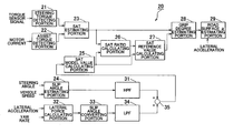
- FIG. 1 is a block diagram showing a configuration of a road surface friction state estimating apparatus according to a first embodiment of the invention;
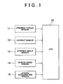
- FIG. 2 is a block diagram showing a functional configuration of an electric control unit (ECU);
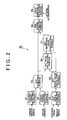
- FIG. 3 is a chart showing an estimated SAT value with respect to a sum of steering torque and assist torque;
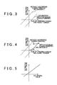
- FIG. 4 is a chart showing the estimated SAT value with respect to the sum of the steering torque and the assist torque, for describing a method of removing a hysteresis characteristic;
- FIG. 5 is a chart showing a relation between a SAT model value and an estimated SAT value;
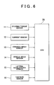
- FIG. 6 is a block diagram showing a configuration of a road surface friction state estimating apparatus according to a second embodiment of the invention; and
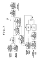
- FIG. 7 is a block diagram showing a functional configuration of an ECU according to the second embodiment of the invention.
- Hereinafter, preferred embodiments of the invention will be described in detail with reference to the accompanying drawings.
- FIG. 1 is a block diagram showing a configuration of a road surface friction state estimating apparatus according to a first embodiment of the invention. The road surface friction state estimating apparatus can be employed, for example, in a vehicle provided with an electric power steering device. Also, the road surface friction state estimating apparatus can be employed in a vehicle provided with a hydraulic power steering device, as described later.
- The road surface friction state estimating apparatus includes a
steering torque sensor 11 which detects steering torque, acurrent sensor 12 which detects motor current, asteering angle sensor 13 which detects a steering angle, avehicle speed sensor 14 which detects a vehicle speed, alateral acceleration sensor 15 which detects a lateral acceleration, and an electronic control unit (hereinafter, referred to as “ECU”) 20 which estimates a road surface friction state using signals output from the sensors. - The
steering torque sensor 11 is disposed coaxially with a steering shaft. Thesteering torque sensor 11 outputs a sensor signal according to steering torque applied to a steering shaft, and supplies the sensor signal to theECU 20. Thecurrent sensor 12 outputs a sensor signal according to the motor current of an electric motor which is used in the electric power steering device, and supplies the sensor signal to theECU 20. - The
steering angle sensor 13 outputs a sensor signal according to a steering angle θP due to the driver's steering operation, and supplies the sensor signal to theECU 20. Thevehicle speed sensor 14 outputs a sensor signal according to a vehicle speed (a vehicle body speed) u, and supplies the sensor signal to theECU 20. Thelateral acceleration sensor 15 outputs a sensor signal according to an acceleration in a lateral direction of the vehicle (a lateral acceleration), and supplies the sensor signal to theECU 20. - FIG. 2 is a block diagram showing a functional configuration of the
ECU 20. TheECU 20 includes a steeringtorque detecting portion 21 which detects steering torque; an assisttorque detecting portion 22 which detects assist torque; aSAT estimating portion 23 which estimates SAT; a slipangle estimating portion 24 which estimates a slip angle; and a SAT modelvalue calculating portion 25 which calculates a SAT model value based on the slip angle. - The
ECU 20 further includes a SATratio calculating portion 26 which calculates a ratio between the estimated SAT value and the SAT model value; a SAT referencevalue calculating portion 27 which calculates a SAT reference value; a gripdegree estimating portion 28 which estimates a grip degree; and a road surface μvalue estimating portion 29 which estimates a road surface friction coefficient (hereinafter, referred to as “a road surface μ value”). - The steering
torque detecting portion 21 detects steering torque applied due to the driver's steering operation based on the sensor signal from thesteering torque sensor 11, and supplies the detected steering torque to theSAT estimating portion 23. - The assist
torque detecting portion 22 detects the assist torque applied to the electric power steering device, based on the motor current based on the sensor signal from thecurrent sensor 12 and a preset parameter (for example, a lead of a pinion, a lead of a ball screw, or an assist motor torque coefficient), and supplies the assist torque to theSAT estimating portion 23. The assisttorque detecting portion 22 may use a current command value output to a motor of the electric power steering device, instead of the motor current. - The
SAT estimating portion 23 calculates a sum of the steering torque detected by the steeringtorque detecting portion 21 and the assist torque detected by the assisttorque detecting portion 22, thereby estimating SAT generated between a road surface and a tire, while removing friction of a steering system. - FIG. 3 is a chart showing an estimated SAT value with respect to the sum of the steering torque and the assist torque. A width between two straight lines shows a magnitude of a hysteresis characteristic due to the friction of the steering system. An inclination of each straight line is 1.
- FIG. 4 is a chart showing the estimated SAT value with respect to the sum of the steering torque and the assist torque, for describing a method of removing the hysteresis characteristic.
- When the sum of the steering torque and the assist torque is 0 and the slip angle is also 0 while the vehicle moves straight, hysteresis does not occur, and the estimated SAT value is 0.
- When steering is performed and SAT is generated, the estimated SAT value is calculated using an inclination K 1 with respect to the sum of the steering torque and the assist torque. More specifically, the
SAT estimating portion 23 performs a calculation according to the following equation (1) using a discrete logic. - T SAT(k+1)=T SAT(k)+K 1·(T DA(k+1)−T DA(k)) (1)
- In the equation, T SAT is the estimated SAT value, TDA is the sum of the steering torque and the assist torque. The inclination K1 is set to be smaller than 1 in order to indicate that a variation in the estimated SAT value is small even when the sum of the steering torque and the assist torque varies due to Coullomb Friction or the like.
- When steering is performed, the estimated SAT value obtained according to the equation (1) reaches a point A in FIG. 4. Further, when the sum of the steering torque and the assist torque increases, the estimated SAT value increases according to a straight line which indicates a lower limit of the model, that is, the estimated SAT value increases according to an equation (2).
- T SAT(k+1)=T SAT(k)+T DA(k+1)−T DA(k) (2)
- When steering is performed further, the estimated SAT value reaches a point B at which the steering angle stops increasing, and then the sum of the steering torque and the assist torque decreases, the estimated SAT value decreases according to the equation (1) using the inclination K 1. In this region, the estimated SAT value is set such that a variation in the estimated SAT value is small with respect to a variation in the sum of the steering torque and the assist torque. The estimated SAT value is thus set so as not to be influenced by the Coullomb Friction of the power steering device, or the like even if the steering force supplied by the driver varies to a certain degree when the steering angle is maintained while the vehicle is turning.
- When the estimated SAT value decreases from the point B to a point C, and then the sum of the steering torque and the assist torque increases, the estimated SAT value increases toward the point B according to the equation (1). Also, when the sum of the steering torque and the assist torque decreases from the point C due to a decrease in the steering angle, and the estimated SAT value reaches an upper limit of the model, the estimated SAT value decreases according to a straight line indicating the upper limit, that is, the estimated SAT value decreases according to the equation (2). Setting two types of inclinations in this way removes the hysteresis characteristic. Then, the
SAT estimating portion 23 supplies the estimated SAT value thus obtained to the SATratio calculating portion 26 and the gripdegree estimating portion 28. - The slip
angle estimating portion 24 estimates a front wheel slip angle αE[rad] which is a slip angle of a front tire, based on a steering angle θP[rad] and a vehicle speed u [m/s]. The steering angle θP is based on the sensor signal from thesteering angle sensor 13, and the vehicle speed u is based on the sensor signal from thevehicle speed sensor 14. The front wheel slip angle αE is represented by state equations (3) and (4), using dynamic characteristics of the vehicle movement.
- In the equations, v is a lateral speed [m/s], r is a yaw rate [rad/s], u is a vehicle speed [m/s], c f is a front wheel cornering power [N/rad], cr is a rear wheel cornering power [N/rad], Lf is a distance between a front axle and a center of gravity of the vehicle [m], Lr is a distance between a rear axle and a center of gravity of the vehicle [m], M is a vehicle mass [kg], IZ is yaw inertia [kgm2], and gh is a steering gear ratio.
- By making the equations (3) and (4) discrete using a sample time τ, the following equations (5) and (6) are obtained.

- In the equations, k is a sampling number. Also, A s and Bs in the equation (5) are represented by the following equations (7).

- The slip
angle estimating portion 24 estimates the front wheel slip angle αE by performing calculations according to the equations (5) to (7), and supplies the front wheel slip angle αE to the SAT modelvalue calculating portion 25 every sample time τ. - The SAT model
value calculating portion 25 calculates the SAT model value using the front wheel slip angle αE. The SAT model value is the SAT value of a model which is made on the assumption that a contact length is a nominal contact length used as a reference for design and a grip degree is high, that is, a linear model which is made linear using a slip angle 0. More specifically, the SAT model value is obtained by the following equation (8). - T m =K O·αE (8)
- In the equation, K O is an inclination of the SAT model value with respect to the front wheel slip angle at a zero point (i.e., a SAT inclination) in the case where there is no change in a load of the vehicle and no reduction in a tire pressure. The SAT model value is represented as a product of the inclination KO and the front wheel slip angle αE as shown in the equation (8). Thus, the SAT model value is a theoretical SAT value in the case where there is no change in the load of the vehicle, no reduction in the tire pressure, and the grip degree is high. The SAT model
value calculating portion 25 supplies the SATratio calculating portion 26 with the SAT model value which is calculated according to the equation (8). - The SAT
ratio calculating portion 26 calculates a SAT ratio (the estimated SAT value/the SAT model value) which is a ratio of the estimated SAT value to the SAT model value, using the estimated SAT value obtained by theSAT estimating portion 23 and the SAT model value calculated by the SAT modelvalue calculating portion 25. The SAT ratio is calculated using an online identification method. More specifically, the SAT ratio is derived according to the equations (9) to (11).
- In the equations, θ is an estimation parameter (a first element: a ratio of the estimated SAT value to the SAT model value, a second element: a drift component generated by a shift in a steering neutral point, and the like), λ is an oblivion coefficient, and k is a sampling number.
- FIG. 5 is a chart showing a relation between the SAT model value and the estimated SAT value. In the calculation algorithm for the SAT ratio in the equations (9) to (11), the estimation parameter θ is obtained. In the parameter θ, a first element is an inclination of a straight line shown in FIG. 5, and a second element is an intercept of the straight line. When there is no shift in the steering neutral point, the intercept as the second element is 0.
- A change in the load of the vehicle and a reduction in the tire pressure occur slowly as compared with behaviors of the vehicle. Therefore, in the calculation algorithm for the SAT ratio, quick response is not required. Accordingly, it is preferable to obtain the estimation parameter 0 based on a trajectory shown in FIG. 5 in the case where the driver repeats the steering operation several times. In the embodiment, an online least squares method is employed.
- The SAT reference
value calculating portion 27 calculates a SAT reference value by adjusting the SAT model value calculated by the SAT modelvalue calculating portion 25 as required based on the SAT ratio supplied by the SATratio calculating portion 26. - More specifically, the SAT reference
value calculating portion 27 determines whether or not a maximum value of the SAT ratio exceeds a threshold value in a predetermined time. When the maximum value of the SAT ratio does not exceed the threshold value in the predetermined time, the SAT referencevalue calculating portion 27 outputs the SAT model value as the SAT reference value. - Meanwhile, when the maximum value of the SAT ratio exceeds the threshold value in the predetermined time, the SAT reference
value calculating portion 27 determines that the contact length between the tire and the road surface increases due to an increase in the load of the vehicle or a reduction in the tire pressure, and the SAT inclination increases. Then, the SAT referencevalue calculating portion 27 obtains the SAT reference value by adjusting the SAT model value upwardly. For upward adjustment, the following equation (12) is used. - T SATOm =T SATO ·γ (12)
- In the equation, T SATOm is the SAT reference value, TSATO is the SAT model value before adjustment, and γ is a parameter for upward adjustment and is the maximum value of the SAT ratio in the predetermined time in the embodiment. As the threshold value, for example, “1.2” is used. Considering that the tire pressure is not adjusted during running, γ may be set as a parameter which does not decrease, as long as the vehicle is not stopped for a given time or more. The SAT reference
value calculating portion 27 supplies the gripdegree estimating portion 28 with the SAT reference value TSATmO thus obtained. - The grip
degree estimating portion 28 estimates a grip degree ε according to the following equation (13) based on the estimated SAT value TSAT estimated by theSAT estimating portion 23 and the SAT reference value TSATmO calculated by the SAT referencevalue calculating portion 27.
- The invention is not limited to a configuration in which the grip
degree estimating portion 28 estimates the grip degree ε using the aforementioned method. For example, the grip degree ε may be represented using a function of the SAT reference value TSATmO and the estimated SAT value TSAT. Alternatively, the grip degree ε may be represented using a two-dimensional map of the SAT reference value TSATmO and the estimated SAT value TSAT. - The road surface μ
value estimating portion 29 estimates a road surface μ value based on the grip degree ε and the lateral acceleration gy when the grip degree ε estimated by the gripdegree estimating portion 28 becomes equal to or smaller than a predetermined reference value (for example, when the grip degree ε becomes equal to or smaller than 0.5). The lateral acceleration gy is based on the sensor signal from thelateral acceleration sensor 15. - The road surface μ value is represented by the following equation (14).

- In the equation, g is a gravitational acceleration. Also, g fy is a front wheel position lateral acceleration, and is represented by the following equation (15).

- The estimation accuracy of the road surface μ value thus obtained is improved as the grip degree ε decreases, that is, the grip degree ε approaches a limit value. Accordingly, when the grip degree ε becomes equal to or smaller than the predetermined reference value as described above, the road surface μ estimating
portion 29 estimates the road surface μ value according to the equations (14) and (15). - As described above, the road surface friction state estimating apparatus according to the first embodiment calculates the SAT model value as the SAT reference value, and estimates a road surface friction state based on the SAT reference value and the estimated SAT value when the contact length between the tire and the road surface remains the same as in the initial state.
- When the contact length between the tire and the road surface increases due to an increase in the superimposed load of the vehicle or a reduction in the tire pressure, and the inclination of SAT with respect to the slip angle increases, it is possible to calculate the SAT reference value considering the current estimated SAT value in addition to the SAT model value. Thus, it is possible to accurately estimate the grip degree ε equivalent to an excess of a frictional force in the lateral direction as a road surface friction state, according to a change in the contact length between the tire and the road surface. Also, it is possible to accurately estimate the road surface μ value when the grip degree ε becomes equal to or smaller than the reference value.
- Next, a second embodiment of the invention will be described. The same portions as in the first embodiment are denoted by the same reference numerals, and duplicate description thereof will be omitted.
- FIG. 6 is a block diagram showing a configuration of a road surface friction state estimating apparatus according to the second embodiment. The road surface friction state estimating apparatus further includes a
yaw rate sensor 16 which detects a yaw rate, in addition to the configuration shown in FIG. 1. - FIG. 7 is a block diagram showing a functional configuration of the
ECU 20. In addition to the configuration shown in FIG. 2, theECU 20 further includes ahigh pass filter 31 which performs high pass filter processing on the slip angle estimated by the slipangle estimating portion 24; a lateralforce calculating portion 32 which calculates a front wheel lateral force of the vehicle; a slipangle converting portion 33 which converts the front wheel lateral force into a slip angle; alow pass filter 34 which performs low pass filter processing on the slip angle obtained by conversion; and a summingdevice 35 which sums the two slip angles on each of which the filter processing has been performed. - The
high pass filter 31 performs high pass filter processing on the front wheel slip angle αE estimated by the slipangle estimating portion 24. When the steering neutral point shifts during running on a bank road, the front wheel slip angle αE estimated by the slipangle estimating portion 24 contains a drift error in a low frequency region, but contains a signal component which does not have a phase lag with respect to the estimated SAT value in a high frequency region. Therefore, thehigh pass filter 31 removes the drift error in the low frequency region and extracts only the high frequency component which does not have a phase lag with respect to the estimated SAT value, by performing the high pass filter processing on the front wheel slip angle αE. - The
high pass filter 31 is configured as a primary discrete filter. The primary high pass filter during a continuous time is represented by the equation (16) which is a transfer function.
- In the equation, ω b is a breakpoint frequency. The high pass filter during a discrete time can be designed by transforming the equation (16), for example, by a Tustin transform. In the Tustin transform, when the sampling time is T and a time lead operator is z, a differential sign s is represented by the equation (17).

- By substituting the equation (17) into the equation (16), the high pass filter during a discrete time is represented by the equation (18).

- The
high pass filter 31 performs the high pass filter processing on the front wheel slip angle αE according to the equation (18), and supplies the summingdevice 35 with the front wheel slip angle αE on which the high pass filter processing has been performed. - The lateral
force calculating portion 32 calculates a front wheel lateral force Ff which is a lateral force generated in a front tire, using a lateral acceleration gy and a yaw rate r. The lateral acceleration gy is based on the sensor signal from thelateral acceleration sensor 15, and the yaw rate r is based the sensor signal from theyaw rate sensor 16. - The front wheel lateral force F f satisfies the equation of motion (19) concerning the lateral acceleration gy, and satisfies the equation of motion (20) concerning the yaw rate r.

- In the equations, F r is a rear lateral force. The lateral acceleration gy is represented by the following equation (21).

- Based on the equations (19) and (20), the front wheel lateral force F f is represented by the following (22).

- The lateral
force calculating portion 32 calculates the front wheel lateral force Ff using the yaw rate r and the lateral acceleration gy according to the equation (22), and supplies the slipangle converting portion 33 with the front wheel lateral force Ff. - The slip
angle converting portion 33 converts the front wheel lateral force Ff into a front wheel slip angle αT by dividing the front wheel lateral force Ff supplied by the lateralforce calculating portion 32 by a front wheel cornering power cf. More particularly, the slipangle converting portion 33 performs a calculation according to the following equation (23).
- The
low pass filter 34 performs low pass filter processing on the front wheel slip angle αT calculated by the slipangle converting portion 33. The front wheel slip angle αT calculated by the slipangle converting portion 33 contains, in the high frequency region, a variation component such as noise due to road surface disturbance and a phase lag. However, the front wheel slip angle αT contains the low frequency component which is not influenced by the road surface disturbance even when the vehicle runs on a bank road. Thus, thelow pass filter 34 removes the variation component in the high frequency region and extracts only the low frequency component which is accurately calculated, by performing the low pass filter processing on the front wheel slip angle αT. - More specifically, the
low pass filter 34 is configured as a primary discrete filter having the same breakpoint frequency as that of thehigh pass filter 31. The primary low pass filter during a continuous time is represented by the following equation (24) which is a transfer function.
- The low pass filter during a discrete time is obtained by transforming the equation (24) by the Tustin transform, and is represented by the following equation (25).

- The
low pass filter 34 performs the low pass filter processing on the front wheel slip angle αT according to the equation (25), and supplies the summingdevice 35 with the front wheel slip angle αT on which the filter processing has been performed. - The invention is not limited to a specific breakpoint frequency. However, the breakpoint frequency is preferably set so as to change in accordance with a road surface cant change speed, that is, a speed at which a cant of the road surface changes, in order to remove noise due to road surface disturbance.
- The summing
device 35 calculates an integrated slip angle αI by summing the front wheel slip angle αE supplied by thehigh pass filter 31 and the front wheel slip angle αT supplied by thelow pass filter 34. In other words, the summingdevice 35 performs a calculation according to the following equation (26). - αI =G H(Z)·αE(Z)+G L(Z)·αT(Z) (26)
- The sum of the transfer function of the
high pass filter 31 and the transfer function of thelow pass filter 34 is 1. Therefore, when the same signal is input to the high pass filter and the low pass filter, and outputs of both the filters are summed, the original signal is restored. Accordingly, the summingdevice 35 can calculate the slip angle αI which is not influenced by a drift error or noise. - The SAT model
value calculating portion 25 calculates the SAT model value in the case where there is no change in the load of the vehicle and no reduction in the tire pressure, using the integrated slip angle αI obtained by the summingdevice 35. More specifically, the SAT modelvalue calculating portion 25 performs a calculation according to the following equation (27). - T m =K O·αI (27)
- Thus, the SAT model
value calculating portion 25 can accurately calculate the SAT model value in the case where there is no change in the load of the vehicle and no reduction in the tire pressure, without being influenced by a drift error due to a shift in the steering neutral point or noise due to road disturbance or the like during running on a bank road. - The SAT
ratio calculating portion 26 calculates the SAT ratio (the estimated SAT value/the SAT model value), using the estimated SAT value obtained by theSAT estimating portion 23 and the SAT model value calculated by the SAT modelvalue calculating portion 25. In the embodiment, the SAT ratio is derived according to the following equations (28) to (30).
- In the equations, θ is an estimation parameter (a ratio of the estimated SAT value to the SAT model value). In other words, only the SAT ratio is used as the estimation parameter θ. Also, P[k] in the equations (29), (30) is a scalar value, while P[k] in the equations (10), (11) in the first embodiment is a matrix with 2 rows and 2 columns.
- Thus, according to the embodiment, since the SAT
ratio calculating portion 26 does not need to consider a drift error due to a shift in the steering neutral point, a second element of the parameter θ is not required. Therefore, it is possible to greatly reduce a load of the online identification calculation which is performed when calculating the SAT ratio. Each of the SAT referencevalue calculating portion 27, the gripdegree estimating portion 28, and the road surface μvalue estimating portion 29 performs the same calculation processing as in the first embodiment. - As described above, the road surface friction state estimating apparatus according to the embodiment can accurately estimate the grip degree ε and the road surface μ value by calculating the SAT reference value T SATmO based on the integrated slip angle which has been extracted by the
high pass filter 31 and thelow pass filter 34, and calculating the ratio between the SAT reference value TSATmO and the estimated SAT value TSAT estimated by theSAT estimating portion 23. - Particularly, the road surface friction state estimating apparatus can remove a drift error due to a shift in the steering neutral point during running on a bank road, and can accurately estimate a road surface friction state without being influenced by road disturbance, by using the
high pass filter 31 and thelow pass filter 34. Further, since the road surface friction state estimating apparatus calculates the SAT ratio without considering a drift error, the load of the online identification calculation can be reduced. - The breakpoint frequency of the
high pass filter 31 and thelow pass filter 34 may be a fixed frequency. However, the breakpoint frequency needs to be set to be equal to or higher than a road surface cant change speed, that is, a speed at which a cant of a road surface changes. The road surface cant change speed is proportional to a vehicle speed. Thus, thehigh pass filter 31 andlow pass filter 34 may be configured such that the breakpoint frequency becomes higher as the vehicle speed becomes higher. - Since the road surface friction state estimating apparatus is provided with the
high pass filter 31 and thelow pass filter 34 thus configured, the apparatus can accurately estimate a road surface friction state even when the vehicle enters a bank road at a high speed. - Also, the
high pass filter 31 and thelow pass filter 34 may be configured such that the breakpoint frequency becomes higher as a deviation between the estimated slip angle value αE and the converted slip angle value αT (i.e., the slip angle value αT obtained by conversion) becomes larger. This is because the deviation between the estimated slip angle value αE and the converted slip angle value αT becomes large in the case where the vehicle runs on a bank road, or in the case where the relation between the lateral force and the slip angle becomes non-linear. In such a case, it is preferable to use the converted slip angle value αT which is based on the front wheel lateral force Ff. that is not influenced by a change in the steering neutral point or the non-linear relation between the lateral force and the slip angle. - Since the road surface friction state estimating apparatus is provided with the
high pass filter 31 and thelow pass filter 34, the apparatus can increase a proportion of the converted slip angle value αT based on the front wheel lateral force Ff to the estimated slip angle value αE based on the steering angle when using the converted slip angle value αT and the estimated slip angle value αE to obtain the integrated slip angle αI, according to the vehicle movement state. As a result, the road surface friction state estimating apparatus can accurately estimate a road surface friction state, for example, even when the vehicle suddenly enters a bank road, or the vehicle is suddenly brought into a spin state. - The invention is not limited to the aforementioned embodiments, and various modifications can be made to the design within the scope of the invention defined by claims.
- For example, in the aforementioned embodiments, the grip degree and the road surface μ value are estimated using the electric power steering device. However, a hydraulic power steering device may be used. When the hydraulic power steering device is used, it is possible to estimate the grip degree and the road surface μ value in the same manner as in the aforementioned embodiments, by measuring a hydraulic pressure and the like of the hydraulic power steering device, and detecting torque corresponding to the steering torque and torque corresponding to the assist torque.
- In the aforementioned embodiments, the
high pass filter 31 and thelow pass filter 34 are represented using the linear transfer functions. However, other functions may be used.
Claims (9)
1. A self aligning torque reference value calculating apparatus comprising:
a self aligning torque estimating portion which estimates a self aligning torque applied to a tire;
a slip angle estimating portion which estimates a slip angle of the tire;
a self aligning torque model value calculating portion which calculates a self aligning torque model value using the slip angle estimated by the slip angle estimating portion;
a self aligning torque ratio calculating portion which calculates a self aligning torque ratio which is a ratio between the self aligning torque estimated by the self aligning torque estimating portion and the self aligning torque model value calculated by the self aligning torque model value calculating portion; and
a self aligning torque reference value calculating portion which calculates a self aligning torque reference value based on the self aligning torque ratio and the self aligning torque model value when a maximum value of the self aligning torque ratio calculated by the self aligning torque ratio calculating portion exceeds a threshold value.
2. The apparatus according to claim 1 , wherein the self aligning torque reference value calculating portion outputs the self aligning torque model value as the self aligning torque reference value when the maximum value of the self aligning torque ratio does not exceed the threshold value.
3. The apparatus according to claim 1 , wherein the self aligning torque reference value calculating portion calculates the self aligning torque reference value by summing the self aligning torque ratio and the self aligning torque model value.
4. The apparatus according to claim 1 further comprising:
a high pass filter which performs high pass filter processing on the slip angle estimated by the slip angle estimating portion;
a lateral force calculating portion which calculates a lateral force applied to the tire;
a low pass filter which performs low pass filter processing on the slip angle obtained by conversion by the slip angle converting portion; and
a summing portion which sums the slip angle on which the high pass filter processing has been performed by the high pass filter and the slip angle on which the low pass filter processing has been performed by the low pass filter, wherein the self aligning torque model value calculating portion calculates the self aligning torque model value based on the slip angle obtained by summation by the summing portion.
5. A road surface friction state estimating apparatus comprising:
a self aligning torque estimating portion which estimates a self aligning torque applied to a tire;
a slip angle estimating portion which estimates a slip angle of the tire;
a self aligning torque model value calculating portion which calculates a self aligning torque model value using the slip angle estimated by the slip angle estimating portion;
a self aligning torque ratio calculating portion which calculates a self aligning torque ratio which is a ratio between the self aligning torque estimated by the self aligning torque estimating portion and the self aligning torque model value calculated by the self aligning torque model value calculating portion;
a self aligning torque reference value calculating portion which calculates a self aligning torque reference value based on the self aligning torque ratio and the self aligning torque model value when a maximum value of the self aligning torque ratio calculated by the self aligning torque ratio calculating portion exceeds a threshold value; and
a road surface friction state estimating portion which estimates a road surface friction state based on the self aligning torque estimated by the self aligning torque estimating portion and the self aligning torque reference value calculated by the self aligning torque reference value calculating portion.
6. The apparatus according to claim 5 , wherein the road surface friction state estimating portion estimates a grip degree of the tire as the road surface friction state, based on a ratio between the self aligning torque and the self aligning torque reference value.
7. The apparatus according to claim 6 , wherein the road surface friction state estimating portion estimates a road surface friction coefficient based on the grip degree and a lateral acceleration.
8. A self aligning torque reference value calculating method comprising the steps of:
estimating self aligning torque applied to a tire;
estimating a slip angle of the tire;
calculating a self aligning torque model value using the estimated slip angle;
calculating a self aligning torque ratio which is a ratio between the estimated self aligning torque and the calculated self aligning torque model value; and
calculating a self aligning torque reference value based on the self aligning torque ratio and the self aligning torque model value when a maximum value of the calculated self aligning torque ratio exceeds a threshold value.
9. A road surface friction state estimating method comprising:
estimating a self aligning torque applied to a tire;
estimating a slip angle of the tire;
calculating a self aligning torque model value using the slip angle estimated;
calculating a self aligning torque ratio which is a ratio between the self aligning torque estimated and the self aligning torque model value calculated;
calculating a self aligning torque reference value based on the self aligning torque ratio and the self aligning torque model value when a maximum value of the self aligning torque ratio calculated exceeds a threshold value; and
estimating a road surface friction state based on the self aligning torque estimated and the self aligning torque reference value calculated.
Applications Claiming Priority (2)
| Application Number | Priority Date | Filing Date | Title |
|---|---|---|---|
| JP2002234586A JP3860518B2 (en) | 2002-08-12 | 2002-08-12 | Road friction estimation device |
| JP2002-234586 | 2002-08-12 |
Publications (1)
| Publication Number | Publication Date |
|---|---|
| US20040133330A1 true US20040133330A1 (en) | 2004-07-08 |
Family
ID=31492455
Family Applications (1)
| Application Number | Title | Priority Date | Filing Date |
|---|---|---|---|
| US10/626,577 Abandoned US20040133330A1 (en) | 2002-08-12 | 2003-07-25 | Self aligning torque reference value calculating apparatus, method thereof, and road surface friction state estimating apparatus, method thereof |
Country Status (3)
| Country | Link |
|---|---|
| US (1) | US20040133330A1 (en) |
| JP (1) | JP3860518B2 (en) |
| DE (1) | DE10337086A1 (en) |
Cited By (29)
| Publication number | Priority date | Publication date | Assignee | Title |
|---|---|---|---|---|
| US20050005691A1 (en) * | 2002-08-12 | 2005-01-13 | Toyota Jidosha Kabushiki Kaisha | Road surface friction state estimating apparatus and method thereof |
| US20080294355A1 (en) * | 2004-03-23 | 2008-11-27 | Thomas Berthold | Tire Lateral Force Determination in Electrical Steering Systems |
| US20080294313A1 (en) * | 2007-05-25 | 2008-11-27 | Nsk Ltd. | Electric power steering apparatus |
| US20090271061A1 (en) * | 2008-04-25 | 2009-10-29 | Wang Dexin | System and method for tire cornering power estimation and monitoring |
| US20100010712A1 (en) * | 2006-05-12 | 2010-01-14 | David Rubia | Method and device for improving driving comfort in a steering assistance system |
| EP2189356A2 (en) * | 2008-11-19 | 2010-05-26 | Hyundai Mobis Co., Ltd. | Method for compensating steering of motor drive power steering system |
| US20100145566A1 (en) * | 2006-11-21 | 2010-06-10 | Ning Bian | Method and facility for estimating a measure of friction |
| US20100256870A1 (en) * | 2009-04-07 | 2010-10-07 | Gm Global Technology Operations, Inc. | Friction estimation and detection for an electric power steering system |
| US20120209475A1 (en) * | 2011-02-16 | 2012-08-16 | Steering Solutions Ip Holding Corporation | Electric Power Steering Control Methods And Systems Using Hysteresis Compensation |
| US20160101782A1 (en) * | 2014-10-09 | 2016-04-14 | GM Global Technology Operations LLC | Methods and systems for estimating road surface friction coefficient using self aligning torque |
| US20170168500A1 (en) * | 2015-12-10 | 2017-06-15 | Uber Technologies, Inc. | System and method to determine traction ability of vehicles in operation |
| US20170297611A1 (en) * | 2016-04-13 | 2017-10-19 | Ford Global Technologies, Llc | Steering assist system and related methods |
| US10220852B2 (en) | 2015-12-16 | 2019-03-05 | Uber Technologies, Inc. | Predictive sensor array configuration system for an autonomous vehicle |
| US10310605B2 (en) | 2016-11-15 | 2019-06-04 | Steering Solutions Ip Holding Corporation | Haptic feedback for steering system controls |
| US10329827B2 (en) | 2015-05-11 | 2019-06-25 | Uber Technologies, Inc. | Detecting objects within a vehicle in connection with a service |
| US10384708B2 (en) | 2016-09-12 | 2019-08-20 | Steering Solutions Ip Holding Corporation | Intermediate shaft assembly for steer-by-wire steering system |
| US10399591B2 (en) | 2016-10-03 | 2019-09-03 | Steering Solutions Ip Holding Corporation | Steering compensation with grip sensing |
| US10449927B2 (en) | 2017-04-13 | 2019-10-22 | Steering Solutions Ip Holding Corporation | Steering system having anti-theft capabilities |
| US10459087B2 (en) | 2016-04-26 | 2019-10-29 | Uber Technologies, Inc. | Road registration differential GPS |
| US10489686B2 (en) | 2016-05-06 | 2019-11-26 | Uatc, Llc | Object detection for an autonomous vehicle |
| US10678262B2 (en) | 2016-07-01 | 2020-06-09 | Uatc, Llc | Autonomous vehicle localization using image analysis and manipulation |
| US10712160B2 (en) | 2015-12-10 | 2020-07-14 | Uatc, Llc | Vehicle traction map for autonomous vehicles |
| US10712742B2 (en) | 2015-12-16 | 2020-07-14 | Uatc, Llc | Predictive sensor array configuration system for an autonomous vehicle |
| US10726280B2 (en) | 2016-03-09 | 2020-07-28 | Uatc, Llc | Traffic signal analysis system |
| CN111527002A (en) * | 2017-11-14 | 2020-08-11 | 尼亚布科知识产权控股有限责任公司 | Torque modulation to linearize tire slip characteristics |
| US10780915B2 (en) | 2016-12-07 | 2020-09-22 | Steering Solutions Ip Holding Corporation | Vehicle steering system having a user experience based automated driving to manual driving transition system and method |
| CN113978470A (en) * | 2021-12-13 | 2022-01-28 | 郑州轻工业大学 | On-line rapid estimation method for friction force between tire and road surface |
| US11334753B2 (en) | 2018-04-30 | 2022-05-17 | Uatc, Llc | Traffic signal state classification for autonomous vehicles |
| US20220289274A1 (en) * | 2019-08-09 | 2022-09-15 | Nidec Corporation | Electric power steering apparatus, control device used in electric power steering apparatus, and control method |
Families Citing this family (12)
| Publication number | Priority date | Publication date | Assignee | Title |
|---|---|---|---|---|
| DE102005002614A1 (en) * | 2005-01-20 | 2006-08-03 | Bayerische Motoren Werke Ag | Steering system for a motor vehicle |
| JP2008081006A (en) * | 2006-09-28 | 2008-04-10 | Mitsubishi Electric Corp | Vehicle traveling control device |
| JP2009006985A (en) * | 2007-05-25 | 2009-01-15 | Nsk Ltd | Electric power steering apparatus |
| JP5195132B2 (en) * | 2007-08-10 | 2013-05-08 | 日本精工株式会社 | Steering angle estimation device for vehicle and electric power steering device equipped with the same |
| DE102009002245B4 (en) * | 2009-04-07 | 2018-05-03 | Robert Bosch Automotive Steering Gmbh | Method for determining the coefficient of friction between the tire and the road surface in a vehicle |
| US8634986B2 (en) * | 2011-03-30 | 2014-01-21 | GM Global Technology Operations LLC | Friction-based state of health indicator for an electric power steering system |
| JP5910265B2 (en) * | 2012-04-11 | 2016-04-27 | トヨタ自動車株式会社 | Vehicle control device |
| DE102016110791A1 (en) | 2015-06-15 | 2016-12-15 | Steering Solutions Ip Holding Corporation | Gesture control for a retractable steering wheel |
| US10496102B2 (en) | 2016-04-11 | 2019-12-03 | Steering Solutions Ip Holding Corporation | Steering system for autonomous vehicle |
| DE102017108692A1 (en) * | 2016-04-25 | 2017-10-26 | Steering Solutions Ip Holding Corporation | Control of electric power steering using system state predictions |
| JP2021089164A (en) * | 2019-12-02 | 2021-06-10 | Toyo Tire株式会社 | Driving support system and driving support method |
| JPWO2023048085A1 (en) * | 2021-09-27 | 2023-03-30 |
Citations (5)
| Publication number | Priority date | Publication date | Assignee | Title |
|---|---|---|---|---|
| US3956931A (en) * | 1973-11-06 | 1976-05-18 | Uniroyal Inc. | Method for determining the preferred direction of rotation of a tire |
| US5636121A (en) * | 1993-12-28 | 1997-06-03 | Mazda Motor Corporation | Traction control system for motor vehicle |
| US6556911B2 (en) * | 2000-06-29 | 2003-04-29 | Fuji Jukogyo Kabushiki Kaisha | Road friction coefficient estimating apparatus and vehicle equipped with road friction coefficient estimating apparatus |
| US6754615B1 (en) * | 1999-03-12 | 2004-06-22 | Avl Deutschland Gmbh | Method of simulating the performance of a vehicle on a road surface |
| US6792343B2 (en) * | 2002-05-24 | 2004-09-14 | Aisin Seiki Kabushiki Kaisha | Antiskid braking control system |
-
2002
- 2002-08-12 JP JP2002234586A patent/JP3860518B2/en not_active Expired - Fee Related
-
2003
- 2003-07-25 US US10/626,577 patent/US20040133330A1/en not_active Abandoned
- 2003-08-12 DE DE10337086A patent/DE10337086A1/en not_active Withdrawn
Patent Citations (5)
| Publication number | Priority date | Publication date | Assignee | Title |
|---|---|---|---|---|
| US3956931A (en) * | 1973-11-06 | 1976-05-18 | Uniroyal Inc. | Method for determining the preferred direction of rotation of a tire |
| US5636121A (en) * | 1993-12-28 | 1997-06-03 | Mazda Motor Corporation | Traction control system for motor vehicle |
| US6754615B1 (en) * | 1999-03-12 | 2004-06-22 | Avl Deutschland Gmbh | Method of simulating the performance of a vehicle on a road surface |
| US6556911B2 (en) * | 2000-06-29 | 2003-04-29 | Fuji Jukogyo Kabushiki Kaisha | Road friction coefficient estimating apparatus and vehicle equipped with road friction coefficient estimating apparatus |
| US6792343B2 (en) * | 2002-05-24 | 2004-09-14 | Aisin Seiki Kabushiki Kaisha | Antiskid braking control system |
Cited By (49)
| Publication number | Priority date | Publication date | Assignee | Title |
|---|---|---|---|---|
| US6898966B2 (en) * | 2002-08-12 | 2005-05-31 | Toyota Jidosha Kabushiki Kaisha | Road surface friction state estimating apparatus and method thereof |
| US20050005691A1 (en) * | 2002-08-12 | 2005-01-13 | Toyota Jidosha Kabushiki Kaisha | Road surface friction state estimating apparatus and method thereof |
| US20080294355A1 (en) * | 2004-03-23 | 2008-11-27 | Thomas Berthold | Tire Lateral Force Determination in Electrical Steering Systems |
| US20100010712A1 (en) * | 2006-05-12 | 2010-01-14 | David Rubia | Method and device for improving driving comfort in a steering assistance system |
| US8688326B2 (en) * | 2006-05-12 | 2014-04-01 | Robert Bosch Gmbh | Method and device for improving driving comfort in a steering assistance system |
| US20100145566A1 (en) * | 2006-11-21 | 2010-06-10 | Ning Bian | Method and facility for estimating a measure of friction |
| US8370019B2 (en) * | 2006-11-21 | 2013-02-05 | Continental Automotive Gmbh | Method and facility for estimating a measure of friction |
| US20080294313A1 (en) * | 2007-05-25 | 2008-11-27 | Nsk Ltd. | Electric power steering apparatus |
| US8290662B2 (en) * | 2008-04-25 | 2012-10-16 | Ford Global Technologies, Llc | System and method for tire cornering power estimation and monitoring |
| US20090271061A1 (en) * | 2008-04-25 | 2009-10-29 | Wang Dexin | System and method for tire cornering power estimation and monitoring |
| US8589025B2 (en) * | 2008-04-25 | 2013-11-19 | Ford Global Technologies, Llc | Tire cornering power on-board estimation and monitoring using steering moment |
| EP2189356A2 (en) * | 2008-11-19 | 2010-05-26 | Hyundai Mobis Co., Ltd. | Method for compensating steering of motor drive power steering system |
| EP2189356A3 (en) * | 2008-11-19 | 2010-12-01 | Hyundai Mobis Co., Ltd. | Method for compensating steering of motor drive power steering system |
| US9150244B2 (en) * | 2009-04-07 | 2015-10-06 | Steering Solutions Ip Holding Corporation | Friction estimation and detection for an electric power steering system |
| US20100256870A1 (en) * | 2009-04-07 | 2010-10-07 | Gm Global Technology Operations, Inc. | Friction estimation and detection for an electric power steering system |
| US20120209475A1 (en) * | 2011-02-16 | 2012-08-16 | Steering Solutions Ip Holding Corporation | Electric Power Steering Control Methods And Systems Using Hysteresis Compensation |
| US8589031B2 (en) * | 2011-02-16 | 2013-11-19 | Steering Solutions Ip Holding Corporation | Electric power steering control methods and systems using hysteresis compensation |
| US10272919B2 (en) * | 2014-10-09 | 2019-04-30 | Gm Global Technology Operations, Llc | Methods and systems for estimating road surface friction coefficient using self aligning torque |
| US20160101782A1 (en) * | 2014-10-09 | 2016-04-14 | GM Global Technology Operations LLC | Methods and systems for estimating road surface friction coefficient using self aligning torque |
| CN105510223A (en) * | 2014-10-09 | 2016-04-20 | 通用汽车环球科技运作有限责任公司 | Methods and systems for estimating road surface friction coefficient using self aligning torque |
| US10662696B2 (en) | 2015-05-11 | 2020-05-26 | Uatc, Llc | Detecting objects within a vehicle in connection with a service |
| US10329827B2 (en) | 2015-05-11 | 2019-06-25 | Uber Technologies, Inc. | Detecting objects within a vehicle in connection with a service |
| US11505984B2 (en) | 2015-05-11 | 2022-11-22 | Uber Technologies, Inc. | Detecting objects within a vehicle in connection with a service |
| US20170168500A1 (en) * | 2015-12-10 | 2017-06-15 | Uber Technologies, Inc. | System and method to determine traction ability of vehicles in operation |
| US10712160B2 (en) | 2015-12-10 | 2020-07-14 | Uatc, Llc | Vehicle traction map for autonomous vehicles |
| US10220852B2 (en) | 2015-12-16 | 2019-03-05 | Uber Technologies, Inc. | Predictive sensor array configuration system for an autonomous vehicle |
| US10712742B2 (en) | 2015-12-16 | 2020-07-14 | Uatc, Llc | Predictive sensor array configuration system for an autonomous vehicle |
| US10684361B2 (en) | 2015-12-16 | 2020-06-16 | Uatc, Llc | Predictive sensor array configuration system for an autonomous vehicle |
| US11462022B2 (en) | 2016-03-09 | 2022-10-04 | Uatc, Llc | Traffic signal analysis system |
| US10726280B2 (en) | 2016-03-09 | 2020-07-28 | Uatc, Llc | Traffic signal analysis system |
| US9944314B2 (en) * | 2016-04-13 | 2018-04-17 | Ford Global Technologies, Llc | Steering assist system and related methods |
| US20170297611A1 (en) * | 2016-04-13 | 2017-10-19 | Ford Global Technologies, Llc | Steering assist system and related methods |
| US11487020B2 (en) | 2016-04-26 | 2022-11-01 | Uatc, Llc | Satellite signal calibration system |
| US10459087B2 (en) | 2016-04-26 | 2019-10-29 | Uber Technologies, Inc. | Road registration differential GPS |
| US10489686B2 (en) | 2016-05-06 | 2019-11-26 | Uatc, Llc | Object detection for an autonomous vehicle |
| US10719083B2 (en) | 2016-07-01 | 2020-07-21 | Uatc, Llc | Perception system for autonomous vehicle |
| US10739786B2 (en) | 2016-07-01 | 2020-08-11 | Uatc, Llc | System and method for managing submaps for controlling autonomous vehicles |
| US10678262B2 (en) | 2016-07-01 | 2020-06-09 | Uatc, Llc | Autonomous vehicle localization using image analysis and manipulation |
| US10852744B2 (en) | 2016-07-01 | 2020-12-01 | Uatc, Llc | Detecting deviations in driving behavior for autonomous vehicles |
| US10871782B2 (en) | 2016-07-01 | 2020-12-22 | Uatc, Llc | Autonomous vehicle control using submaps |
| US10384708B2 (en) | 2016-09-12 | 2019-08-20 | Steering Solutions Ip Holding Corporation | Intermediate shaft assembly for steer-by-wire steering system |
| US10399591B2 (en) | 2016-10-03 | 2019-09-03 | Steering Solutions Ip Holding Corporation | Steering compensation with grip sensing |
| US10310605B2 (en) | 2016-11-15 | 2019-06-04 | Steering Solutions Ip Holding Corporation | Haptic feedback for steering system controls |
| US10780915B2 (en) | 2016-12-07 | 2020-09-22 | Steering Solutions Ip Holding Corporation | Vehicle steering system having a user experience based automated driving to manual driving transition system and method |
| US10449927B2 (en) | 2017-04-13 | 2019-10-22 | Steering Solutions Ip Holding Corporation | Steering system having anti-theft capabilities |
| CN111527002A (en) * | 2017-11-14 | 2020-08-11 | 尼亚布科知识产权控股有限责任公司 | Torque modulation to linearize tire slip characteristics |
| US11334753B2 (en) | 2018-04-30 | 2022-05-17 | Uatc, Llc | Traffic signal state classification for autonomous vehicles |
| US20220289274A1 (en) * | 2019-08-09 | 2022-09-15 | Nidec Corporation | Electric power steering apparatus, control device used in electric power steering apparatus, and control method |
| CN113978470A (en) * | 2021-12-13 | 2022-01-28 | 郑州轻工业大学 | On-line rapid estimation method for friction force between tire and road surface |
Also Published As
| Publication number | Publication date |
|---|---|
| DE10337086A1 (en) | 2004-03-04 |
| JP2004074845A (en) | 2004-03-11 |
| JP3860518B2 (en) | 2006-12-20 |
Similar Documents
| Publication | Publication Date | Title |
|---|---|---|
| US20040133330A1 (en) | Self aligning torque reference value calculating apparatus, method thereof, and road surface friction state estimating apparatus, method thereof | |
| US6898966B2 (en) | Road surface friction state estimating apparatus and method thereof | |
| US6804584B2 (en) | Method for determining the roll angle of a vehicle using an estimation of road bank angle | |
| US6351694B1 (en) | Method for robust estimation of road bank angle | |
| EP0363570B1 (en) | Road surface friction sensor and road surface friction coefficient detector, and vehicle antilock braking device | |
| US6768283B2 (en) | Electric power steering control device | |
| US7366598B2 (en) | Device for estimating drift amount of lateral acceleration sensor, device for correcting output of lateral acceleration sensor, and device for estimating road surface friction state | |
| US6802226B2 (en) | Physical amount estimating apparatus, road surface friction condition estimating apparatus, steering angle neutral point estimating apparatus and air pressure reduction estimating apparatus | |
| US6614343B1 (en) | Method for determining vehicle status variables | |
| US6601435B2 (en) | Method and device for estimating a friction coefficient between a tire and a road surface | |
| US6526804B2 (en) | Road friction coefficient estimating apparatus for vehicle | |
| US20080126009A1 (en) | Method of estimating mass of vehicle | |
| US8370019B2 (en) | Method and facility for estimating a measure of friction | |
| US6619422B2 (en) | Steering unit and internal drag calculation apparatus used therein | |
| JP4071529B2 (en) | Self-aligning torque estimation device and lateral grip degree estimation device | |
| US20030089542A1 (en) | Method of estimating quantities that represent state of vehicle | |
| US7164974B2 (en) | Vehicle roll sensing using load shift estimation | |
| EP2855239A1 (en) | Sensory feedback when driving near a vehicle's handling limits | |
| JP3271953B2 (en) | Road surface friction coefficient estimation device for vehicles | |
| JPH0550938A (en) | Rear wheel steering angle control device | |
| KR20000003072A (en) | Road-surface friction coefficient inferring method using angular velocity sensor and car electronic controlling device thereof |
Legal Events
| Date | Code | Title | Description |
|---|---|---|---|
| AS | Assignment |
Owner name: TOYOTA JIDOSHA KABUSHIKI KAISHA, JAPAN Free format text: ASSIGNMENT OF ASSIGNORS INTEREST;ASSIGNORS:ONO, EIICHI;INAGAKI, SHOJI;REEL/FRAME:014352/0751 Effective date: 20030707 |
|
| STCB | Information on status: application discontinuation |
Free format text: ABANDONED -- FAILURE TO RESPOND TO AN OFFICE ACTION |