US20040008973A1 - Method and system for synchronizing operation of remote timer with centeral control control unit - Google Patents
Method and system for synchronizing operation of remote timer with centeral control control unit Download PDFInfo
- Publication number
- US20040008973A1 US20040008973A1 US10/427,235 US42723503A US2004008973A1 US 20040008973 A1 US20040008973 A1 US 20040008973A1 US 42723503 A US42723503 A US 42723503A US 2004008973 A1 US2004008973 A1 US 2004008973A1
- Authority
- US
- United States
- Prior art keywords
- slave
- clock
- time signals
- time
- signals
- Prior art date
- Legal status (The legal status is an assumption and is not a legal conclusion. Google has not performed a legal analysis and makes no representation as to the accuracy of the status listed.)
- Abandoned
Links
Images


Classifications
-
- H—ELECTRICITY
- H04—ELECTRIC COMMUNICATION TECHNIQUE
- H04J—MULTIPLEX COMMUNICATION
- H04J3/00—Time-division multiplex systems
- H04J3/02—Details
- H04J3/06—Synchronising arrangements
- H04J3/0635—Clock or time synchronisation in a network
- H04J3/0638—Clock or time synchronisation among nodes; Internode synchronisation
- H04J3/0658—Clock or time synchronisation among packet nodes
- H04J3/0661—Clock or time synchronisation among packet nodes using timestamps
- H04J3/0664—Clock or time synchronisation among packet nodes using timestamps unidirectional timestamps
-
- G—PHYSICS
- G06—COMPUTING; CALCULATING OR COUNTING
- G06F—ELECTRIC DIGITAL DATA PROCESSING
- G06F1/00—Details not covered by groups G06F3/00 - G06F13/00 and G06F21/00
- G06F1/04—Generating or distributing clock signals or signals derived directly therefrom
- G06F1/12—Synchronisation of different clock signals provided by a plurality of clock generators
-
- G—PHYSICS
- G06—COMPUTING; CALCULATING OR COUNTING
- G06F—ELECTRIC DIGITAL DATA PROCESSING
- G06F1/00—Details not covered by groups G06F3/00 - G06F13/00 and G06F21/00
- G06F1/04—Generating or distributing clock signals or signals derived directly therefrom
- G06F1/14—Time supervision arrangements, e.g. real time clock
Definitions
- This invention relates generally to the keeping time in a computer system and, more particularly, to synchronization of a clock at a remote site with a master clock.
- EPG electronic program guide
- the EPG is a rudimentary example of an interactive television application exploiting the capability of the digital broadcast medium to transmit additional content and for the STB to execute this additional content.
- the computer functionality of STBs also makes other interactive television applications possible. With appropriately configured STBs, users potentially can play along with game shows, take tests in on-line distance learning courses, bid in on-line auctions, and otherwise actively engage the content being broadcast. STBs thus allow users to have highly interactive television experiences.
- One type of additional content application which is desirable in such a broadcast environment is one which provides functionality synchronized with video or audio content on a broadcast channel.
- providing application-specific behaviors appropriately coordinated with video and audio streams presents a number of concerns.
- a first method embeds synchronization points within the application data content to asynchronously initiate the additional content.
- SMPTE Society for Motion Picture and Television Engineers
- An application or program 100 is embedded with a number of trigger points 102 .
- An application (not shown) executing the program 100 then monitors the video time codes 104 or frame numbers 106 and, using conventional conditional logic, determines when a trigger point 102 has been reached.
- the application (not shown) can then execute specific program logic to generate the change in appearance or behavior associated with the trigger points 102 .
- This method is self-contained in that the encoded synchronization points can initiate display of the additional content.
- this method does suffer a disadvantage in that it consumes a significant amount of programming logic and a corresponding amount of program memory within the STB to operate. It also will be appreciated that, if there is a miscommunication in transmission of the reference point, none of the synchronization points will execute at the appropriate time.
- a second method shown in FIG. 1B involves a control operator 120 transmitting control signals at a broadcast site from which a program 122 is being transmitted can transmit control signals 124 to initiate the additional content.
- the control operator 120 might engage a semi-automatic computer application (not shown) to monitor the program 122 and view previously conceived timelines. Using such a system, the control operator 120 in real time could actuate a control device to insert trigger signals 124 into the broadcast stream at the appropriate times.
- the application executing the program 122 receives these trigger signals 124 , interprets the instructions encoded therewith, and then effects the desired change in behavior or appearance of the program related to the additional content.
- the code needed to initiate the additional content may have been previously stored in the program memory, or may be transmitted along with the trigger signals 124 .
- This method is used in the Advanced Television Enhancement Forum (“ATVEF”) standard for interactive television over analog channels.
- ATVEF Advanced Television Enhancement Forum
- This second approach has the potential advantage of using less computer memory resources than does the first method. Nonetheless, this approach presents its own concerns.
- sending trigger signals 124 requires human intervention during the broadcast. Further, real-time bandwidth capable of supporting this remote control of the content is required.
- multiplexing of the digital signals can result in signals such as the trigger signals 124 being transmitted at different times. This results in a potentially ever-shifting offset between the transmission of the trigger signals 124 and their receipt.
- the process of multiplexing the trigger signals into the digital broadcast stream results in signal jitter which, in turn, results in clock phase jitter at sites receiving the timing signals.
- STBs can be equipped with their own slave clocks to be synchronized to a master clock at a broadcast site.
- placing slave clocks in the STBs may not solve the problems previously described.
- slave clocks may incorporate inexpensive parts.
- the slave clocks might exhibit significant clock drift on the order of one part in a thousand. Consequently, an application running on an STB with such a clock could be off by nearly two seconds by the end of a half-hour program, and that is assuming the slave clock was perfectly synchronized at the outset of the program.
- a potential solution to redress timing drift in the slave clocks is to periodically synchronize the slave clocks to the master clock. This solution, however, presents additional concerns.
- FIG. 2 shows a graph 200 plotting timing of local timing signals 210 versus timing of master clock signals 220 in an ideal system.
- the slave clock is synchronized with the master clock and the slave clock rate accurately tracks the master clock rate.
- a master clock generates a regular sequence 230 of master clock signals 240 .
- a sequence 250 of slave clock signals 260 is generated.
- the slope of the lines representing the sequences 230 and 250 shows that the clocks track at the same rates.
- a difference between them is an offset 270 representing a propagation delay resulting from a time it takes for a synchronization signal from the master broadcast site to be received and processed.
- This offset 270 typically is negligible because it is small, is consistent across the network, and corresponds with a similar offset in broadcast of other video and audio content.
- the slave clock signals 260 track the master clock signals 240 save for an acceptable propagation delay offset 270 .
- FIG. 3 shows a graph 300 of one possible scenario in which a slave clock does not accurately track a master clock.
- the graph 300 plots timing of local timing signals 310 versus timing of master clock signals 320 .
- the slave clock signals 360 are initially synchronized to the master clock signals 240 .
- a sequence of the slave clock signals 350 proceeds differently than that of the sequence of master clock signals 330 .
- the slave clock in this example runs faster than the slave clock.
- any difference caused by a propagation delay offset 370 subsequently closes over time as the slave clock time sequence 350 overtakes the master clock time sequence 330 as shown by an intersection 380 of the sequences.
- the timing of the program on the receiving device driven by the slave clock signals 360 will be out of synchronization with the program. The time signals triggering events will come earlier and earlier until the application may become unworkable.
- One solution to a timing creep problem as shown in FIG. 3 is to regularly resynchronize the slave clock with the master clock. Although the slave clock rate may not accurately track the master clock rate, regular resynchronization of the clocks can reduce the discrepancy to a manageable level. Unfortunately, in a digital broadcast environment where timing signals have to be multiplexed, resulting jitter can undermine the synchronization process.
- FIG. 4 shows a graph 400 illustrating the synchronization problems caused by jitter in the master clock signals caused by multiplexing or other effects.
- the graph 400 plots an absolute time 410 on the horizontal axis and a time generated/received 420 on the vertical axis.
- the sequence 450 of slave clock signals 460 runs at a consistent rate. Unfortunately, as described in connection with FIG. 3, this rate may be wrong. However, attempting to synchronize the sequence 450 of slave clock signals 460 with the gerrymandering sequence 430 of master clock signals 440 would present problems of its own. Jitter in the master clock signals 440 results in a jagged sequence 430 of the master clock signals 440 .
- Resynchronizing the slave clock signals 460 over a long term might result in an average whereby the slave clock rate more accurately tracks the master clock rate.
- synchronizing at times shown would result in ongoing jitter in the slave clock signals 460 .
- Such jitter could result in abrupt changing of program attributes.
- a forward adjustment of the slave clock time signals 460 could result in that program event being ignored.
- Such triggering of program events is described in a co-pending patent application entitled “METHOD AND SYSTEM FOR FLEXIBLE TIME-BASED CONTROL OF APPLICATION APPEARANCE AND BEHAVIOR,” bearing attorney docket number ENSE-I-1004.
- Undesirable effects of jitter also can be considered mathematically.
- the master clock emits a reference signal M 0 .
- the signal is received by the slave clock as M 0 ′.
- the delay can be considered as having two components, a mean delay P and the deviation from the mean resulting from jitter J 0 . Therefore, the master clock signal received by the slave clock can be written as:
- the slave clock time when the signal is received is S 0 .
- the apparent error E 0 between the slave clock time and the master clock time can be written as:
- the slave clock will be behind (slow) by the amount of the propagation delay, as expected, but also behind or ahead by the amount of the jitter J 0 .
- M 1 ′ M 0 + ⁇ +P+J 1 ,
- the elapsed time at the slave clock D 0 1 between the first perceived master clock signal M 0 ′ and the second perceived master clock signal M 1 ′ incorporates jitter affecting both perceived signals
- E 1 (S 0 +D 0 1 ) ⁇ M 1 .
- E 1 E 0 +J 1 ⁇ J 0 .
- the measured differential error at the second reference signal E 1 ⁇ E 0 will be the sum of the jitters of the first and second signal J 1 ⁇ J 0 . Therefore, while the mean differential error between any two reference signals will be zero (the expected value of (J i+1 -J i )), the variance of the differential error (the expected value of (J i+1 -J i ) 2 ) is increased by a factor of two.
- Embodiments of the present invention facilitate synchronizing a slave clock with a master clock to avoid the effects of jitter in transmitted master clock signals. Effects of jitter are reduced by collecting a set of master clock time signals and averaging an error between the slave clock time signals and the master clock time signals. Repeating this process allows for correcting the slave clock time signals to correspond with the master clock signals over time without introducing abrupt timing shifts caused by jitter.
- embodiments of the present invention provide a method, a computer readable medium, and a system for synchronizing a slave clock time with reference time signals received from a master clock.
- a first basis set of reference time signals received from a master clock is collected.
- a first comparison set of slave time signals from a slave clock is identified such that each of the slave clock time signals in the first comparison set corresponds with receipt of each of the reference time signals in the first basis set.
- a difference between each of the reference time signals in the first basis set and the slave time signals in the first comparison set is calculated.
- Embodiments of the invention can be configured to respond to a stop indicator signaling that the slave clock time should be stopped. Upon the stop indicator being rescinded, the slave clock is synchronized to a master clock reference signal and then resynchronized over time as previously described.
- the synchronization process repeats using subsequently collected second basis and second comparison sets of time signals.
- the slave time can be adjusted incrementally, such as by portions of the average difference. Also, over time cumulative average differences can be calculated to facilitate slave time adjustment. Intervals between synchronizations can be selected to reduce overhead of continual or constant synchronization.
- Embodiments of the invention allow for a slave clock to be associated with a local device and a master clock associated with a remote device, allowing synchronization of local devices across a network.
- the local device can receive reference signals from a wired or wireless network which can be a media broadcast network.
- FIG. 1A is a timeline of timing reference signals for a hypothetical prior art interactive software application using embedded timing reference signals
- FIG. 1B is another timeline of timing reference signals for a hypothetical prior art interactive software application using asynchronously broadcast timing reference signals
- FIG. 2 shows a graph plotting master clock generated timing reference signals and slave clock generated timing reference signals in a hypothetical conventional system where the slave clock rate accurately tracks the master clock rate;
- FIG. 3 shows a graph plotting a master clock generated timing reference signals and slave clock generated timing reference signals in a hypothetical conventional system where the slave clock rate inaccurately tracks the master clock rate;
- FIG. 4 shows a graph plotting master clock generated timing reference signals affected by jitter as received at a remote location and slave clock generated timing reference signals in a hypothetical conventional system
- FIG. 5 is a flowchart of a routine using an embodiment of the present invention for adjusting a slave time kept by slave clock;
- FIG. 6 is a flowchart of a routine using a second embodiment of the present invention for adjusting a slave time kept by a slave clock in an environment where the slave time can be stopped by a received signal;
- FIG. 7 is a block diagram of a data processing/media control system for broadcasting master reference time signals and/or for receiving and responding to time reference signals according to an embodiment of the present invention.
- embodiments of the present invention provide a method, a computer readable medium, and a system for synchronizing a slave clock time with reference time signals received from a master clock.
- a first basis set of reference time signals received from a master clock is collected.
- a first comparison set of slave time signals from a slave clock is identified such that each of the slave time signals in the first comparison set corresponds with receipt of each of reference time signals in the first basis set.
- a difference between each of the reference time signals in the first basis set and the slave time signals in the first comparison set is calculated.
- Embodiments of the invention can be configured to respond to a stop indicator signaling that the slave clock time should be stopped. Upon the stop indicator being rescinded, the slave clock is synchronized to a master clock reference signal, then resynchronized over time as previously described.
- Embodiments of the present invention reduce variance of actual error between the master clock signals and the slave clock signals. Variances in a slave clock rate and a master clock rate can be adjusted by periodically synchronizing the slave clock to the master clock. Thus, to focus on the manner in which embodiments of the present invention reduce undesirable effects of jitter, it is assumed that the master clock and the slave clock track at the same clock rate.
- the master clock emits a reference signal M 0
- the signal is received by the slave clock as M 0 ′
- a relative delay consists of a mean delay P and the deviation from the mean resulting from jitter J 0
- the mean delay is caused by the time required to create, multiplex and broadcast the reference signal.
- broadcast propagation time between a broadcast site and individual receiving locations will vary from one to another.
- this variation is small relative to the mean delay.
- the mean delay at any one receiving location is constant, and the variation of the mean delay across a network is small, the imprecision introduced by ignoring the mean delay suitably is neglected.
- the mean delay can be compensated by appropriately adjusting the value of the reference time in the synchronization signal.
- the synchronization signal is transmitted once every two seconds.
- the apparent offset is measured for four consecutive received sync signals, and the offsets averaged.
- the clock is then set according to the average offset value.
- One minute later the process is repeated. Therefore, once started, synchronization takes no longer than ten seconds to occur, and is updated at least once every 70 seconds. If the master and slave clock do not have the same rate, E i ′ is a function of time, and the averaging process yields an time-averaged value for E′.
- the difference in rates is not sufficient to introduce a significant error when re-synchronization occurs each minute.
- FIG. 5 shows a flowchart of a routine 500 for synchronizing a slave clock according to an embodiment of the present invention.
- a first reference time signal from the master clock is received.
- the slave clock time is synchronized to the master clock time contained in the first reference signal.
- an error accumulator which is used to accumulate total error between master clock reference time signals in the basis set and the slave clock time signals in comparison set, is set to zero.
- a master clock reference time signal is read and an error representing a difference between the master clock reference time signal and a slave time signal generated at a time corresponding to receipt of the master clock reference time signal is calculated and added to an accumulator total.
- a decision block 512 it is determined if enough master clock reference time signals and slave time signals to form the desired basis set and comparison set, respectively, have been compared and their differences accumulated. If not, the routine 500 loops to the block 510 to read the next master clock reference time signal and add to the cumulative error stored in the accumulator. If enough master clock reference time signals and slave time signals to form the desired basis set and comparison set, respectively, have been compared and their differences accumulated, at a block 514 a mean error is computed and applied to adjust the slave clock.
- a next master clock reference signal is received and counted but substantively ignored.
- a second embodiment of the present invention accounts for situations in which, at a broadcast site, it is desired to stop the running of the slave clocks at remote locations. For example, if in the midst of a game show broadcast a news bulletin is issued, the broadcaster may wish to pause the game. The broadcaster may appropriately desire that slave clocks be stopped so that when the game show broadcast resumes, users also can resume their interaction with the game with appropriate synchronization. The broadcaster can stop the slave clocks by transmitting a stop indicator such as a status flag or status bit associated with the master clock reference time signals. Suitably equipped STBs or other receivers receiving the stop indicator cease execution of the slave clock. When the stop indicator is reset, cleared, or otherwise rescinded, the slave clock is resynchronized with the master clock, and a continuing resynchronization process resumes.
- a stop indicator such as a status flag or status bit associated with the master clock reference time signals.
- STBs or other receivers receiving the stop indicator cease execution of the slave clock.
- FIG. 6 shows a flowchart of a routine 600 for synchronizing a slave clock according to a second embodiment of the present invention incorporating the previously described stop indicator.
- a first reference time signal from the master clock is received.
- the slave clock time is synchronized to the master clock time contained in the first reference signal.
- an error accumulator which is used to accumulate total error between master clock reference time signals in the basis set and the slave clock time signals in comparison set, is set to zero.
- a master clock reference time signal is read and an error representing a difference between the master clock reference time signal and a slave time signal generated at a time corresponding to receipt of the master clock reference time signal is calculated and added to an accumulator total.
- a stop indicator is received indicating the master clock is paused. If so, at a block 614 a master clock reference time signal is read and at a decision block 616 it is determined if the stop indicator has been rescinded indicating if the master clock is still paused. If the master clock is no longer paused as indicated by rescinding of the stop indicator, the routine 600 loops to the block 606 to resynchronize the slave clock. If the master clock is still paused, the routine 600 loops to the block 614 to read the next master clock reference time signal.
- an error representing a difference between the master clock reference time signal and a slave time signal generated at a time corresponding to receipt of the master clock reference signal is calculated and added to an accumulator total. Operation of the error accumulator is equivalent to that described in connection with the routine 500 (FIG. 5).
- a decision block 620 it is determined if enough master clock reference time signals and slave time signals to form the desired basis set and comparison set, respectively, have been compared and their differences accumulated. If not, the routine 600 loops to the block 610 to read the next master clock reference time signal. If enough master clock reference time signals and slave time signals to form the desired basis set and comparison set, respectively, have been compared and their differences accumulated, at a block 622 a mean error is computed and applied to adjust the slave clock.
- a next master clock reference signal is received and counted but substantively ignored.
- a decision block 626 it is determined whether a stop indicator has been received indicating the master clock has been paused. If so, the routine 600 loops to the block 614 to read a next master clock reference time signal. If not, at a decision block 628 , it is determined whether enough master clock reference time signals have been ignored so as to warrant another synchronization process. If so, the routine 600 loops to the block 608 to zero the accumulator and continue with the synchronization process previously described. If not enough master clock reference time signals have been ignored, the routine 600 loops to the block 624 to continue receiving, counting, and substantively ignoring the content of the signals. Again, it will be appreciated that the waiting process manifested in blocks 624 and 628 could also be performed by a timer rather than by counting a number of reference signals.
- the slave clock can accumulate a series of values for the clock offset E i ′. This offset can be used to further smooth the variance of error between the master clock and the slave clock.
- adjustments could be applied to the slave clock incrementally over a period of time instead of all at once. For example, the average difference calculated between the basis set and the comparison set could be divided into a number of units and applied in increments of that same number.
- FIG. 7 shows a computer system 700 operable for generating programs at a broadcast location or for executing programs using embodiments of the present invention.
- the system 700 could be a STB or other receiver responsive to master clock time reference signals as previously described.
- the computer system 700 is operable for controlling a display 702 , such as a television, and an audio subsystem 704 , such as a stereo or a loudspeaker system.
- the computer system 700 receives input from or sends output through a network 706 , such as a broadband data network.
- the computer system 700 also receives or sends user input from a wired or wireless user keypad 708 , which may be in the nature of a keyboard, STB remote, or other device.
- the computer system 700 receives input from and sends output to the network 706 via an input/output controller 710 , which directs signals to and from a video controller 712 , an audio controller 714 , and a central processing unit (CPU) 716 .
- the input/output controller 710 suitably is a multiplexer for routing video data blocks received from the network 706 to a video controller 712 in the nature of a video decoder, audio data blocks to an audio controller 714 in the nature of an audio decoder, and for routing other data blocks to a CPU 716 for processing.
- the CPU 716 communicates through a system controller 718 with input and storage devices such as read only memory (ROM) 720 , system memory 722 , system storage 724 , and input device controller 726 .
- ROM read only memory
- the CPU is driven by a clock 717 .
- the clock 717 is a slave clock which can be synchronized with master clock reference time signals according to embodiments of the invention as previously described.
- computer program code instructions could be stored in the system memory 722 and executed by the CPU 716 to apply corrections to the slave clock.
- the clock 717 suitably is a master clock from which master clock reference time signals are transmitted over the network 706 .
- the system 700 also can include devices or be programmed with instructions to respond to and generate stop indicators signaling when the master clock is paused.
Abstract
Description
- This invention claims priority from U.S. Provisional Application No. 60/395,651, entitled “METHOD AND SYSTEM FOR SYNCHRONIZING OPERATION OF REMOTE TIMER WITH CENTRAL CONTROL UNIT,” filed Jul. 12, 2002.
- This invention relates generally to the keeping time in a computer system and, more particularly, to synchronization of a clock at a remote site with a master clock.
- The improved price-performance of digital technology has made possible the advent of digital media broadcasting. The reduced cost of microprocessors, digital memory, and related devices has made it possible to place computers in set-top boxes (STBs) and related devices to receive digital cable or digital satellite television signals and decode those signals into audio-visual programs.
- The advent of digital television broadcasting and the proliferation of STBs also makes it possible to enhance viewers' television experiences. In addition to transmitting video and audio data, digital media broadcasting allows additional data to be transmitted to the STBs with which users can interact. By analogy, users can interact through an STB with data transmitted via the digital media broadcast the way a computer user can interact with data available over the Internet. For example, digital television subscribers are already acquainted with an electronic program guide (EPG) function which enables users to select and tune to particular programs and/or read about the programs being shown at present or at later points in time.
- The EPG is a rudimentary example of an interactive television application exploiting the capability of the digital broadcast medium to transmit additional content and for the STB to execute this additional content. The computer functionality of STBs also makes other interactive television applications possible. With appropriately configured STBs, users potentially can play along with game shows, take tests in on-line distance learning courses, bid in on-line auctions, and otherwise actively engage the content being broadcast. STBs thus allow users to have highly interactive television experiences.
- One type of additional content application which is desirable in such a broadcast environment is one which provides functionality synchronized with video or audio content on a broadcast channel. In the examples of interactive game shows, on-line distance learning testing, and on-line auctions, it would be highly desirable to provide application-specific behaviors in an STB which are correlated to associated video and audio streams being broadcast. However, providing application-specific behaviors appropriately coordinated with video and audio streams presents a number of concerns.
- An important concern is in synchronizing and maintaining the synchronization of a clock used to drive an interactive application to ensure that the application performs as desired by the creators and broadcasters of the application. In the examples listed above, manifest problems can result if a local clock driving an interactive application is out of synchronization with a master clock at a broadcast site. Users playing along with game shows might not be given the time to answer questions indicated by a host displayed on the screen. Students taking on-line tests might be given time to answer a question after the correct answer already had been displayed. Bidders in on-line auctions could win against higher bidders or lose against lower bidders because of timing inequalities among the bidders' systems. Clearly, maintaining synchronization of the local clocks regulating users' interaction with the interactive applications is an important concern.
- Conventionally, timing of users' local clocks is regulated using a number of methods. A first method embeds synchronization points within the application data content to asynchronously initiate the additional content. For example, Society for Motion Picture and Television Engineers (SMPTE) time codes or frame numbers, counted from a selected reference point, can be used to trigger additional content as shown in FIG. 1A. An application or
program 100 is embedded with a number oftrigger points 102. An application (not shown) executing theprogram 100 then monitors thevideo time codes 104 orframe numbers 106 and, using conventional conditional logic, determines when atrigger point 102 has been reached. The application (not shown) can then execute specific program logic to generate the change in appearance or behavior associated with thetrigger points 102. This method is self-contained in that the encoded synchronization points can initiate display of the additional content. However, this method does suffer a disadvantage in that it consumes a significant amount of programming logic and a corresponding amount of program memory within the STB to operate. It also will be appreciated that, if there is a miscommunication in transmission of the reference point, none of the synchronization points will execute at the appropriate time. - A second method shown in FIG. 1B involves a
control operator 120 transmitting control signals at a broadcast site from which aprogram 122 is being transmitted can transmitcontrol signals 124 to initiate the additional content. Thecontrol operator 120 might engage a semi-automatic computer application (not shown) to monitor theprogram 122 and view previously conceived timelines. Using such a system, thecontrol operator 120 in real time could actuate a control device to inserttrigger signals 124 into the broadcast stream at the appropriate times. The application executing theprogram 122 receives thesetrigger signals 124, interprets the instructions encoded therewith, and then effects the desired change in behavior or appearance of the program related to the additional content. The code needed to initiate the additional content may have been previously stored in the program memory, or may be transmitted along with thetrigger signals 124. This method is used in the Advanced Television Enhancement Forum (“ATVEF”) standard for interactive television over analog channels. - This second approach has the potential advantage of using less computer memory resources than does the first method. Nonetheless, this approach presents its own concerns. First, sending
trigger signals 124 requires human intervention during the broadcast. Further, real-time bandwidth capable of supporting this remote control of the content is required. Second, in a digital media broadcast environment, even if thetrigger signals 124 are sent at the appropriate times, limitations of the digital broadcasting medium may make it impossible to control when thetrigger signals 124 will be received. In digital broadcasting, data blocks of video data, audio data, and other data, such as thesetrigger signals 124, all must be multiplexed for transmission. Unlike in an analog environment where signals can be added to a broadcast feed at a desired time, multiplexing of the digital signals can result in signals such as thetrigger signals 124 being transmitted at different times. This results in a potentially ever-shifting offset between the transmission of thetrigger signals 124 and their receipt. In other words, the process of multiplexing the trigger signals into the digital broadcast stream results in signal jitter which, in turn, results in clock phase jitter at sites receiving the timing signals. - To help reduce phase jitter, STBs can be equipped with their own slave clocks to be synchronized to a master clock at a broadcast site. However, placing slave clocks in the STBs may not solve the problems previously described. To keep manufacturing costs low, slave clocks may incorporate inexpensive parts. As a result, the slave clocks might exhibit significant clock drift on the order of one part in a thousand. Consequently, an application running on an STB with such a clock could be off by nearly two seconds by the end of a half-hour program, and that is assuming the slave clock was perfectly synchronized at the outset of the program. A potential solution to redress timing drift in the slave clocks is to periodically synchronize the slave clocks to the master clock. This solution, however, presents additional concerns.
- FIG. 2 shows a
graph 200 plotting timing oflocal timing signals 210 versus timing ofmaster clock signals 220 in an ideal system. In the ideal system, the slave clock is synchronized with the master clock and the slave clock rate accurately tracks the master clock rate. A master clock generates aregular sequence 230 ofmaster clock signals 240. At a receiver equipped with a slave clock, asequence 250 ofslave clock signals 260 is generated. As can be seen from the graph, the slope of the lines representing thesequences offset 270 representing a propagation delay resulting from a time it takes for a synchronization signal from the master broadcast site to be received and processed. Thisoffset 270 typically is negligible because it is small, is consistent across the network, and corresponds with a similar offset in broadcast of other video and audio content. In other words, in the ideal system shown in thegraph 200, theslave clock signals 260 track themaster clock signals 240 save for an acceptablepropagation delay offset 270. - However, in a practical environment, such an ideal system as that described in the
graph 200 of FIG. 2 does not exist. FIG. 3 shows agraph 300 of one possible scenario in which a slave clock does not accurately track a master clock. Again, thegraph 300 plots timing of local timing signals 310 versus timing of master clock signals 320. In this system, the slave clock signals 360 are initially synchronized to the master clock signals 240. However, with the progression of time, a sequence of the slave clock signals 350 proceeds differently than that of the sequence of master clock signals 330. In particular, the slave clock in this example runs faster than the slave clock. Accordingly, any difference caused by a propagation delay offset 370 subsequently closes over time as the slaveclock time sequence 350 overtakes the masterclock time sequence 330 as shown by anintersection 380 of the sequences. Thus, presuming a propagation delay continues with the accompanying video and audio content, the timing of the program on the receiving device driven by the slave clock signals 360 will be out of synchronization with the program. The time signals triggering events will come earlier and earlier until the application may become unworkable. - One solution to a timing creep problem as shown in FIG. 3 is to regularly resynchronize the slave clock with the master clock. Although the slave clock rate may not accurately track the master clock rate, regular resynchronization of the clocks can reduce the discrepancy to a manageable level. Unfortunately, in a digital broadcast environment where timing signals have to be multiplexed, resulting jitter can undermine the synchronization process.
- FIG. 4 shows a
graph 400 illustrating the synchronization problems caused by jitter in the master clock signals caused by multiplexing or other effects. Thegraph 400 plots anabsolute time 410 on the horizontal axis and a time generated/received 420 on the vertical axis. Thesequence 450 of slave clock signals 460 runs at a consistent rate. Unfortunately, as described in connection with FIG. 3, this rate may be wrong. However, attempting to synchronize thesequence 450 of slave clock signals 460 with thegerrymandering sequence 430 of master clock signals 440 would present problems of its own. Jitter in the master clock signals 440 results in ajagged sequence 430 of the master clock signals 440. Resynchronizing the slave clock signals 460 over a long term might result in an average whereby the slave clock rate more accurately tracks the master clock rate. However, synchronizing at times shown would result in ongoing jitter in the slave clock signals 460. Such jitter could result in abrupt changing of program attributes. Moreover, if a program event is keyed to be triggered only if computer program execution had commenced before a particular time is reached, a forward adjustment of the slaveclock time signals 460 could result in that program event being ignored. Such triggering of program events is described in a co-pending patent application entitled “METHOD AND SYSTEM FOR FLEXIBLE TIME-BASED CONTROL OF APPLICATION APPEARANCE AND BEHAVIOR,” bearing attorney docket number ENSE-I-1004. - Undesirable effects of jitter also can be considered mathematically. At a time T the master clock emits a reference signal M 0. After a delay resulting from propagation delay and jitter, the signal is received by the slave clock as M0′. The delay can be considered as having two components, a mean delay P and the deviation from the mean resulting from jitter J0. Therefore, the master clock signal received by the slave clock can be written as:
- M 0 ′=M 0 +P+J 0
- The slave clock time when the signal is received is S 0. Thus, the apparent error E0 between the slave clock time and the master clock time can be written as:
- E 0 =S 0 −M 0
- However, considering the error components in the received master clock signal M 0′, the actual error E0′ inherent as a result of the error components in the received master clock signal M0′ can be derived to be:
- E 0′=S0 −M 0 ′=S 0 M 0 −P−J 0
- E 0 ′=E 0 −P−J 0
- Correcting the slave clock to account for this error, as visually can be appreciated from FIG. 4, incorporates jitter into the slave clock signal S 0. Mathematically, adjusting the slave clock signal S0 as result of the apparent error E0′ directly incorporates the jitter J0 into the adjusted slave clock signal A0:
- A 0 =S 0 −E 0
- Put another way, substituting in the equations shows this adjustment to the slave clock incorporates into the adjusted slave clock signal A 0 a degree or error between the perceived error E0′ and the actual error E0:
- E 0 −E 0 =−P−J 0.
- In other words, the slave clock will be behind (slow) by the amount of the propagation delay, as expected, but also behind or ahead by the amount of the jitter J 0.
- As previously described, jitter continues and varies with time, resulting in potentially runaway error. If the slave clock signal S 0 is set at the receipt of the first synchronization at a time T, at time T+δ the master clock emits a reference signal with time signature M1=M0+δ resulting in perceived signal M1′:
- M 1 ′=M 0 +δ+P+J 1,
- The elapsed time at the slave clock D 01 between the first perceived master clock signal M0′ and the second perceived master clock signal M1′ incorporates jitter affecting both perceived signals

- D 01 =M 1 ′M 0 ′=δ+J 1 −J 0,
- The error in the unadjusted slave clock time E 1 incorporates the elapsed time:
- E 1 =(S 0 +D 01)−M1.
- Substituting shows the effects of the ongoing jitter:
- E 1=(S 0 +δ+J 1 −J 0)−(M 0+δ)
- E 1 =E 0 +J 1 −J 0.
- Thus, if the slave clock is set according to the error determined from the first reference signal, the measured differential error at the second reference signal E 1−E0 will be the sum of the jitters of the first and second signal J1−J0. Therefore, while the mean differential error between any two reference signals will be zero (the expected value of (Ji+1-Ji)), the variance of the differential error (the expected value of (Ji+1-Ji)2) is increased by a factor of two.
- Thus, there is an unmet need in the art for methods and systems for maintaining time on a slave clock accurately tracking a master clock time where reference signals received by the remote clock are subject to propagation delays and jitter.
- Embodiments of the present invention facilitate synchronizing a slave clock with a master clock to avoid the effects of jitter in transmitted master clock signals. Effects of jitter are reduced by collecting a set of master clock time signals and averaging an error between the slave clock time signals and the master clock time signals. Repeating this process allows for correcting the slave clock time signals to correspond with the master clock signals over time without introducing abrupt timing shifts caused by jitter.
- More specifically, embodiments of the present invention provide a method, a computer readable medium, and a system for synchronizing a slave clock time with reference time signals received from a master clock. Using embodiments of the present invention, a first basis set of reference time signals received from a master clock is collected. A first comparison set of slave time signals from a slave clock is identified such that each of the slave clock time signals in the first comparison set corresponds with receipt of each of the reference time signals in the first basis set. A difference between each of the reference time signals in the first basis set and the slave time signals in the first comparison set is calculated. An average difference between each of the reference time signals in the first basis set and the slave time signals in the first comparison set is then calculated and a slave time kept by the slave clock is adjusted by the average difference. Embodiments of the invention can be configured to respond to a stop indicator signaling that the slave clock time should be stopped. Upon the stop indicator being rescinded, the slave clock is synchronized to a master clock reference signal and then resynchronized over time as previously described.
- In accordance with further aspects of the invention, the synchronization process repeats using subsequently collected second basis and second comparison sets of time signals. The slave time can be adjusted incrementally, such as by portions of the average difference. Also, over time cumulative average differences can be calculated to facilitate slave time adjustment. Intervals between synchronizations can be selected to reduce overhead of continual or constant synchronization. Embodiments of the invention allow for a slave clock to be associated with a local device and a master clock associated with a remote device, allowing synchronization of local devices across a network. The local device can receive reference signals from a wired or wireless network which can be a media broadcast network.
- The preferred and alternative embodiments of the present invention are described in detail below with reference to the following drawings.
- FIG. 1A is a timeline of timing reference signals for a hypothetical prior art interactive software application using embedded timing reference signals;
- FIG. 1B is another timeline of timing reference signals for a hypothetical prior art interactive software application using asynchronously broadcast timing reference signals;
- FIG. 2 shows a graph plotting master clock generated timing reference signals and slave clock generated timing reference signals in a hypothetical conventional system where the slave clock rate accurately tracks the master clock rate;
- FIG. 3 shows a graph plotting a master clock generated timing reference signals and slave clock generated timing reference signals in a hypothetical conventional system where the slave clock rate inaccurately tracks the master clock rate;
- FIG. 4 shows a graph plotting master clock generated timing reference signals affected by jitter as received at a remote location and slave clock generated timing reference signals in a hypothetical conventional system;
- FIG. 5 is a flowchart of a routine using an embodiment of the present invention for adjusting a slave time kept by slave clock;
- FIG. 6 is a flowchart of a routine using a second embodiment of the present invention for adjusting a slave time kept by a slave clock in an environment where the slave time can be stopped by a received signal; and
- FIG. 7 is a block diagram of a data processing/media control system for broadcasting master reference time signals and/or for receiving and responding to time reference signals according to an embodiment of the present invention.
- By way of overview, embodiments of the present invention provide a method, a computer readable medium, and a system for synchronizing a slave clock time with reference time signals received from a master clock. Using embodiments of the present invention, a first basis set of reference time signals received from a master clock is collected. A first comparison set of slave time signals from a slave clock is identified such that each of the slave time signals in the first comparison set corresponds with receipt of each of reference time signals in the first basis set. A difference between each of the reference time signals in the first basis set and the slave time signals in the first comparison set is calculated. An average difference between each of the reference time signals in the first basis set and the slave time signals in the first comparison set is then calculated and a slave time kept by the slave clock is adjusted by the average difference. Embodiments of the invention can be configured to respond to a stop indicator signaling that the slave clock time should be stopped. Upon the stop indicator being rescinded, the slave clock is synchronized to a master clock reference signal, then resynchronized over time as previously described.
- Embodiments of the present invention reduce variance of actual error between the master clock signals and the slave clock signals. Variances in a slave clock rate and a master clock rate can be adjusted by periodically synchronizing the slave clock to the master clock. Thus, to focus on the manner in which embodiments of the present invention reduce undesirable effects of jitter, it is assumed that the master clock and the slave clock track at the same clock rate.
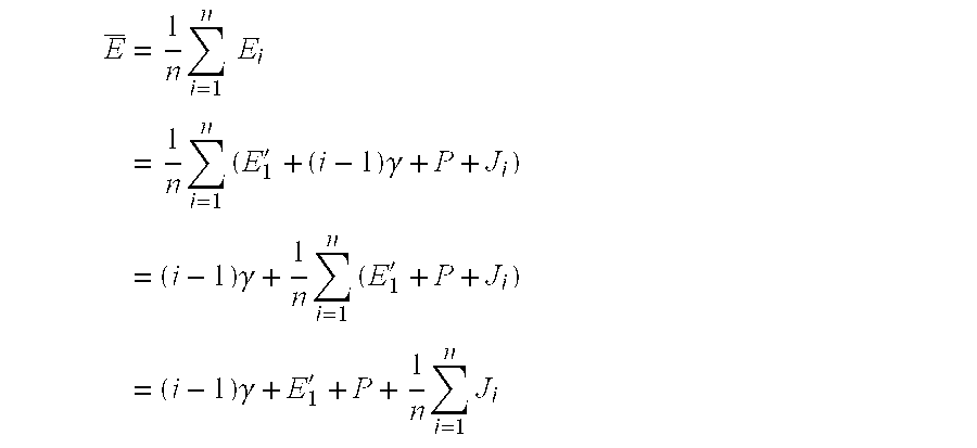
- As previously explained, where the master clock emits a reference signal M 0, the signal is received by the slave clock as M0′, and a relative delay consists of a mean delay P and the deviation from the mean resulting from jitter J0, the master clock signal received by the slave clock can be written as:

- If the master and slave clock have the same rate, then the absolute offset between them E i′ is constant, and so the expected value of
- E i
 =
= E i ′+P+J i=E′+P
 - can be estimated by averaging E;

- Averaging n values reduces the variance of E i by 1/n. It will be appreciated that the mean delay incorporates and thus accounts for the clock offset.
- Also as previously described, the mean delay is caused by the time required to create, multiplex and broadcast the reference signal. Within a network, broadcast propagation time between a broadcast site and individual receiving locations will vary from one to another. However, considering transmission speeds, this variation is small relative to the mean delay. Practically, because the mean delay at any one receiving location is constant, and the variation of the mean delay across a network is small, the imprecision introduced by ignoring the mean delay suitably is neglected. Alternatively, however, if the mean delay can be measured or estimated, the mean delay can be compensated by appropriately adjusting the value of the reference time in the synchronization signal.
- In one presently preferred embodiment, the synchronization signal is transmitted once every two seconds. The apparent offset is measured for four consecutive received sync signals, and the offsets averaged. The clock is then set according to the average offset value. One minute later, the process is repeated. Therefore, once started, synchronization takes no longer than ten seconds to occur, and is updated at least once every 70 seconds. If the master and slave clock do not have the same rate, E i′ is a function of time, and the averaging process yields an time-averaged value for E′. However, for practical devices, the difference in rates is not sufficient to introduce a significant error when re-synchronization occurs each minute.
- FIG. 5 shows a flowchart of a routine 500 for synchronizing a slave clock according to an embodiment of the present invention. At a block 504 a first reference time signal from the master clock is received. At a
block 506, the slave clock time is synchronized to the master clock time contained in the first reference signal. At ablock 508, an error accumulator, which is used to accumulate total error between master clock reference time signals in the basis set and the slave clock time signals in comparison set, is set to zero. At ablock 510, a master clock reference time signal is read and an error representing a difference between the master clock reference time signal and a slave time signal generated at a time corresponding to receipt of the master clock reference time signal is calculated and added to an accumulator total. - At a
decision block 512, it is determined if enough master clock reference time signals and slave time signals to form the desired basis set and comparison set, respectively, have been compared and their differences accumulated. If not, the routine 500 loops to theblock 510 to read the next master clock reference time signal and add to the cumulative error stored in the accumulator. If enough master clock reference time signals and slave time signals to form the desired basis set and comparison set, respectively, have been compared and their differences accumulated, at a block 514 a mean error is computed and applied to adjust the slave clock. - At a
block 516, a next master clock reference signal is received and counted but substantively ignored. At adecision block 518, it is determined whether enough master clock reference time signals have been ignored so as to warrant another synchronization process. If so, the routine 500 loops to theblock 508 to zero the accumulator and continue with the synchronization process previously described. If not enough master clock reference time signals have been ignored, the routine 500 loops to theblock 516 to continue receiving, counting, and substantively ignoring the content of the signals. It will be appreciated that the waiting process manifested inblocks - Referring now to FIG. 6, a second embodiment of the present invention accounts for situations in which, at a broadcast site, it is desired to stop the running of the slave clocks at remote locations. For example, if in the midst of a game show broadcast a news bulletin is issued, the broadcaster may wish to pause the game. The broadcaster may appropriately desire that slave clocks be stopped so that when the game show broadcast resumes, users also can resume their interaction with the game with appropriate synchronization. The broadcaster can stop the slave clocks by transmitting a stop indicator such as a status flag or status bit associated with the master clock reference time signals. Suitably equipped STBs or other receivers receiving the stop indicator cease execution of the slave clock. When the stop indicator is reset, cleared, or otherwise rescinded, the slave clock is resynchronized with the master clock, and a continuing resynchronization process resumes.
- FIG. 6 shows a flowchart of a routine 600 for synchronizing a slave clock according to a second embodiment of the present invention incorporating the previously described stop indicator. At a block 604 a first reference time signal from the master clock is received. At a
block 606, the slave clock time is synchronized to the master clock time contained in the first reference signal. At ablock 608, an error accumulator, which is used to accumulate total error between master clock reference time signals in the basis set and the slave clock time signals in comparison set, is set to zero. At ablock 610, a master clock reference time signal is read and an error representing a difference between the master clock reference time signal and a slave time signal generated at a time corresponding to receipt of the master clock reference time signal is calculated and added to an accumulator total. - At a
decision block 612, it is determined whether a stop indicator is received indicating the master clock is paused. If so, at a block 614 a master clock reference time signal is read and at adecision block 616 it is determined if the stop indicator has been rescinded indicating if the master clock is still paused. If the master clock is no longer paused as indicated by rescinding of the stop indicator, the routine 600 loops to theblock 606 to resynchronize the slave clock. If the master clock is still paused, the routine 600 loops to theblock 614 to read the next master clock reference time signal. - At the
decision block 612, if it is determined that a stop indicator has not been received indicating the master clock is not paused, at ablock 618 an error representing a difference between the master clock reference time signal and a slave time signal generated at a time corresponding to receipt of the master clock reference signal is calculated and added to an accumulator total. Operation of the error accumulator is equivalent to that described in connection with the routine 500 (FIG. 5). At adecision block 620, it is determined if enough master clock reference time signals and slave time signals to form the desired basis set and comparison set, respectively, have been compared and their differences accumulated. If not, the routine 600 loops to theblock 610 to read the next master clock reference time signal. If enough master clock reference time signals and slave time signals to form the desired basis set and comparison set, respectively, have been compared and their differences accumulated, at a block 622 a mean error is computed and applied to adjust the slave clock. - At a
block 624, a next master clock reference signal is received and counted but substantively ignored. At adecision block 626, it is determined whether a stop indicator has been received indicating the master clock has been paused. If so, the routine 600 loops to theblock 614 to read a next master clock reference time signal. If not, at adecision block 628, it is determined whether enough master clock reference time signals have been ignored so as to warrant another synchronization process. If so, the routine 600 loops to theblock 608 to zero the accumulator and continue with the synchronization process previously described. If not enough master clock reference time signals have been ignored, the routine 600 loops to theblock 624 to continue receiving, counting, and substantively ignoring the content of the signals. Again, it will be appreciated that the waiting process manifested inblocks - Further alternative embodiments allow other functionality. In one alternative embodiment, the slave clock can accumulate a series of values for the clock offset E i′. This offset can be used to further smooth the variance of error between the master clock and the slave clock. In addition, adjustments could be applied to the slave clock incrementally over a period of time instead of all at once. For example, the average difference calculated between the basis set and the comparison set could be divided into a number of units and applied in increments of that same number.
- In yet another alternative embodiment, the slave clock can accumulate a series of values for the clock adjustment {overscore (E)} i, and estimate therefrom the rate difference between the slave and master clock. Once determined, this rate difference can be utilized to refine the clock adjustment. For example, if the slave clock operates more slowly than the master clock, an actual offset between the clocks at two consecutive signal times is given by

- An averaging procedure consistent with that previously described results in the computation:
- Using this computation, an estimation of E 1′+P can be corrected for the drift between the clocks.
- FIG. 7 shows a
computer system 700 operable for generating programs at a broadcast location or for executing programs using embodiments of the present invention. Particularly, thesystem 700 could be a STB or other receiver responsive to master clock time reference signals as previously described. - The
computer system 700 is operable for controlling adisplay 702, such as a television, and anaudio subsystem 704, such as a stereo or a loudspeaker system. Thecomputer system 700 receives input from or sends output through anetwork 706, such as a broadband data network. Thecomputer system 700 also receives or sends user input from a wired orwireless user keypad 708, which may be in the nature of a keyboard, STB remote, or other device. - The
computer system 700 receives input from and sends output to thenetwork 706 via an input/output controller 710, which directs signals to and from avideo controller 712, anaudio controller 714, and a central processing unit (CPU) 716. In the case of a STB, the input/output controller 710 suitably is a multiplexer for routing video data blocks received from thenetwork 706 to avideo controller 712 in the nature of a video decoder, audio data blocks to anaudio controller 714 in the nature of an audio decoder, and for routing other data blocks to aCPU 716 for processing. In turn, theCPU 716 communicates through asystem controller 718 with input and storage devices such as read only memory (ROM) 720,system memory 722,system storage 724, andinput device controller 726. - The CPU is driven by a
clock 717. In a receiver or STB, theclock 717 is a slave clock which can be synchronized with master clock reference time signals according to embodiments of the invention as previously described. For example, computer program code instructions could be stored in thesystem memory 722 and executed by theCPU 716 to apply corrections to the slave clock. Alternatively, in a system at a broadcast location, theclock 717 suitably is a master clock from which master clock reference time signals are transmitted over thenetwork 706. It will be appreciated that thesystem 700 also can include devices or be programmed with instructions to respond to and generate stop indicators signaling when the master clock is paused. - While the preferred embodiment of the invention has been illustrated and described, as noted above, many changes can be made without departing from the spirit and scope of the invention. Accordingly, the scope of the invention is not limited by the disclosure of the preferred embodiment. Instead, the invention should be determined entirely by reference to the claims that follow.
Claims (96)
Priority Applications (1)
| Application Number | Priority Date | Filing Date | Title |
|---|---|---|---|
| US10/427,235 US20040008973A1 (en) | 2002-07-12 | 2003-04-30 | Method and system for synchronizing operation of remote timer with centeral control control unit |
Applications Claiming Priority (2)
| Application Number | Priority Date | Filing Date | Title |
|---|---|---|---|
| US39565102P | 2002-07-12 | 2002-07-12 | |
| US10/427,235 US20040008973A1 (en) | 2002-07-12 | 2003-04-30 | Method and system for synchronizing operation of remote timer with centeral control control unit |
Publications (1)
| Publication Number | Publication Date |
|---|---|
| US20040008973A1 true US20040008973A1 (en) | 2004-01-15 |
Family
ID=29736714
Family Applications (1)
| Application Number | Title | Priority Date | Filing Date |
|---|---|---|---|
| US10/427,235 Abandoned US20040008973A1 (en) | 2002-07-12 | 2003-04-30 | Method and system for synchronizing operation of remote timer with centeral control control unit |
Country Status (2)
| Country | Link |
|---|---|
| US (1) | US20040008973A1 (en) |
| EP (1) | EP1380918A2 (en) |
Cited By (15)
| Publication number | Priority date | Publication date | Assignee | Title |
|---|---|---|---|---|
| US20040070594A1 (en) * | 1997-07-12 | 2004-04-15 | Burke Trevor John | Method and apparatus for programme generation and classification |
| US20050039177A1 (en) * | 1997-07-12 | 2005-02-17 | Trevor Burke Technology Limited | Method and apparatus for programme generation and presentation |
| US20050289151A1 (en) * | 2002-10-31 | 2005-12-29 | Trevor Burker Technology Limited | Method and apparatus for programme generation and classification |
| US20060031914A1 (en) * | 2004-02-04 | 2006-02-09 | Jon Dakss | Synchronization and automation in an ITV enviroment |
| WO2009082909A1 (en) * | 2007-12-14 | 2009-07-09 | Huawei Technologies Co., Ltd. | Method for realizing time master-standby protection and time master-standby protection device |
| US7882436B2 (en) | 2004-03-10 | 2011-02-01 | Trevor Burke Technology Limited | Distribution of video data |
| US8571005B1 (en) * | 2005-10-11 | 2013-10-29 | Atmel Corporation | Method and apparatus for synchronization of a master timebase with one or more slave timebases using indirect signalling of timing information |
| US20130343409A1 (en) * | 2012-06-26 | 2013-12-26 | Marvell International Ltd. | Methods and apparatus for precision time stamping |
| US20140033225A1 (en) * | 2012-07-30 | 2014-01-30 | Airbus Operations Sas | Method for monitoring the coordinated execution of sequenced tasks by an electronic card comprising at least two processors synchronized to two different clocks |
| US9465672B2 (en) | 2012-07-30 | 2016-10-11 | Airbus Operations Sas | Method for monitoring the coordinated execution of sequenced tasks by an electronic card comprising at least two processors synchronized to one and the same clock |
| US10158441B1 (en) * | 2017-06-02 | 2018-12-18 | Apple Inc. | Securing time between nodes |
| CN111868662A (en) * | 2018-03-22 | 2020-10-30 | 微软技术许可有限责任公司 | Clock synchronization |
| US20220283981A1 (en) * | 2021-03-08 | 2022-09-08 | Realtek Semiconductor Corp. | Clock synchronization system and operation method thereof capable of synchronizing operation time of internal circuits |
| US11689440B2 (en) | 2019-02-06 | 2023-06-27 | Marvell Israel (M.I.S.L) Ltd. | Method and apparatus for transmit time timestamping |
| US11924318B2 (en) | 2022-02-24 | 2024-03-05 | Marvell Israel (M.I.S.L) Ltd. | Timestamping for multiple synchronization domains in a network device |
Families Citing this family (11)
| Publication number | Priority date | Publication date | Assignee | Title |
|---|---|---|---|---|
| FR2867288B1 (en) * | 2004-03-03 | 2006-06-02 | Centre Nat Rech Scient | METHOD FOR SYNCHRONIZING DATA, IN PARTICULAR DISTRIBUTED, TAKING INTO ACCOUNT IMPREGNITIES AND DERIVATIVES OF CLOCKS |
| US7768931B2 (en) | 2004-10-07 | 2010-08-03 | Westerngeco L.L.C. | Hardware-based network packet timestamps: improved network clock synchronization |
| DE102005036851B3 (en) | 2005-08-04 | 2006-11-23 | Siemens Audiologische Technik Gmbh | Synchronizing signal tones output by hearing aids for binaural hearing aid supply involves sending control signal with count value at which signal tone is to be output from first to second hearing aid, outputting tones when values reached |
| US7539889B2 (en) | 2005-12-30 | 2009-05-26 | Avega Systems Pty Ltd | Media data synchronization in a wireless network |
| US8462627B2 (en) | 2005-12-30 | 2013-06-11 | Altec Lansing Australia Pty Ltd | Media data transfer in a network environment |
| US7987294B2 (en) | 2006-10-17 | 2011-07-26 | Altec Lansing Australia Pty Limited | Unification of multimedia devices |
| EP2080387B1 (en) | 2006-10-17 | 2019-12-18 | D&M Holdings, Inc. | Configuring and connecting to a media wireless network |
| JP2010510695A (en) | 2006-10-17 | 2010-04-02 | アベガ システムズ ピーティーワイ リミテッド | Media distribution in wireless networks |
| KR100872771B1 (en) * | 2007-09-04 | 2008-12-09 | 한국전자통신연구원 | Methods and apparatus for time information synchronization using key re-synchronization frame in encryption communications |
| EP2520986A1 (en) | 2011-05-05 | 2012-11-07 | Markus Bräm | Method and device for autonomous generation of day-dependent time signals without the use of real time clock chips |
| EP3866019A1 (en) * | 2020-02-17 | 2021-08-18 | Be Spoon | Clock-error estimation for two-clock electronic device |
Citations (11)
| Publication number | Priority date | Publication date | Assignee | Title |
|---|---|---|---|---|
| US4503490A (en) * | 1981-06-10 | 1985-03-05 | At&T Bell Laboratories | Distributed timing system |
| US4993003A (en) * | 1988-08-17 | 1991-02-12 | Electronic-Werke Deutschland Gmbh | Apparatus for updating time-of-day information in a signal |
| US5274545A (en) * | 1990-01-29 | 1993-12-28 | The United States Of America As Represented By The Secretary Of Commerce | Device and method for providing accurate time and/or frequency |
| US5528560A (en) * | 1991-11-19 | 1996-06-18 | Seikosha Co., Ltd. | Timepiece receptive of a broadcast time-signal for correcting a time error |
| US5805530A (en) * | 1995-09-05 | 1998-09-08 | Youngberg; C. Eric | System, method, and device for automatic setting of clocks |
| US6236623B1 (en) * | 1998-10-16 | 2001-05-22 | Moore Industries | System and method for synchronizing clocks in a plurality of devices across a communication channel |
| US6278710B1 (en) * | 1998-09-10 | 2001-08-21 | Agilent Technologies, Inc. | Enhancements to time synchronization in distributed systems |
| US6393306B1 (en) * | 1999-01-19 | 2002-05-21 | Agere Systems Guardian Corp. | Automatic clock setting |
| US20030048811A1 (en) * | 2001-09-11 | 2003-03-13 | Robie Edward Adams | Methods, systems and computer program products for synchronizing clocks of nodes on a computer network |
| US6636270B2 (en) * | 2000-12-14 | 2003-10-21 | Microsoft Corporation | Clock slaving methods and arrangements |
| US20070002987A1 (en) * | 2001-02-21 | 2007-01-04 | Pranesh Sinha | Synchronizing clocks across a communication link |
-
2003
- 2003-04-30 US US10/427,235 patent/US20040008973A1/en not_active Abandoned
- 2003-07-11 EP EP03254411A patent/EP1380918A2/en not_active Withdrawn
Patent Citations (11)
| Publication number | Priority date | Publication date | Assignee | Title |
|---|---|---|---|---|
| US4503490A (en) * | 1981-06-10 | 1985-03-05 | At&T Bell Laboratories | Distributed timing system |
| US4993003A (en) * | 1988-08-17 | 1991-02-12 | Electronic-Werke Deutschland Gmbh | Apparatus for updating time-of-day information in a signal |
| US5274545A (en) * | 1990-01-29 | 1993-12-28 | The United States Of America As Represented By The Secretary Of Commerce | Device and method for providing accurate time and/or frequency |
| US5528560A (en) * | 1991-11-19 | 1996-06-18 | Seikosha Co., Ltd. | Timepiece receptive of a broadcast time-signal for correcting a time error |
| US5805530A (en) * | 1995-09-05 | 1998-09-08 | Youngberg; C. Eric | System, method, and device for automatic setting of clocks |
| US6278710B1 (en) * | 1998-09-10 | 2001-08-21 | Agilent Technologies, Inc. | Enhancements to time synchronization in distributed systems |
| US6236623B1 (en) * | 1998-10-16 | 2001-05-22 | Moore Industries | System and method for synchronizing clocks in a plurality of devices across a communication channel |
| US6393306B1 (en) * | 1999-01-19 | 2002-05-21 | Agere Systems Guardian Corp. | Automatic clock setting |
| US6636270B2 (en) * | 2000-12-14 | 2003-10-21 | Microsoft Corporation | Clock slaving methods and arrangements |
| US20070002987A1 (en) * | 2001-02-21 | 2007-01-04 | Pranesh Sinha | Synchronizing clocks across a communication link |
| US20030048811A1 (en) * | 2001-09-11 | 2003-03-13 | Robie Edward Adams | Methods, systems and computer program products for synchronizing clocks of nodes on a computer network |
Cited By (28)
| Publication number | Priority date | Publication date | Assignee | Title |
|---|---|---|---|---|
| US20040070594A1 (en) * | 1997-07-12 | 2004-04-15 | Burke Trevor John | Method and apparatus for programme generation and classification |
| US20050039177A1 (en) * | 1997-07-12 | 2005-02-17 | Trevor Burke Technology Limited | Method and apparatus for programme generation and presentation |
| US20050289151A1 (en) * | 2002-10-31 | 2005-12-29 | Trevor Burker Technology Limited | Method and apparatus for programme generation and classification |
| US8010986B2 (en) * | 2004-02-04 | 2011-08-30 | Ericsson Television, Inc. | Synchronization and automation in an ITV environment |
| US20110271318A1 (en) * | 2004-02-04 | 2011-11-03 | Jon Dakss | Synchronization and automation in an itv environment |
| EP1754373A4 (en) * | 2004-02-04 | 2007-09-26 | Goldpocket Interactive Inc | Synchronization and automation in an itv environment |
| US20060031914A1 (en) * | 2004-02-04 | 2006-02-09 | Jon Dakss | Synchronization and automation in an ITV enviroment |
| EP1754373A2 (en) * | 2004-02-04 | 2007-02-21 | Goldpocket Interactive, Inc. | Synchronization and automation in an itv environment |
| US8505058B2 (en) * | 2004-02-04 | 2013-08-06 | Ericsson Television Inc. | Synchronization and automation in an ITV environment |
| US7882436B2 (en) | 2004-03-10 | 2011-02-01 | Trevor Burke Technology Limited | Distribution of video data |
| US8571005B1 (en) * | 2005-10-11 | 2013-10-29 | Atmel Corporation | Method and apparatus for synchronization of a master timebase with one or more slave timebases using indirect signalling of timing information |
| US8634341B1 (en) * | 2005-10-11 | 2014-01-21 | Atmel Corporation | Method and apparatus for iterative synchronization of two or more electronic devices |
| US8724615B1 (en) | 2005-10-11 | 2014-05-13 | Atmel Corporation | Method and apparatus for generation of a system master timebase of a computing device using indirect signalling of timing information |
| US9191907B2 (en) | 2005-10-11 | 2015-11-17 | Atmel Corporation | Method and apparatus for iterative synchronization of two or more electronic devices |
| WO2009082909A1 (en) * | 2007-12-14 | 2009-07-09 | Huawei Technologies Co., Ltd. | Method for realizing time master-standby protection and time master-standby protection device |
| US9391728B2 (en) | 2012-06-26 | 2016-07-12 | Marvell World Trade Ltd. | Methods and apparatus for precision time stamping |
| US20130343409A1 (en) * | 2012-06-26 | 2013-12-26 | Marvell International Ltd. | Methods and apparatus for precision time stamping |
| CN104380632A (en) * | 2012-06-26 | 2015-02-25 | 马维尔国际贸易有限公司 | Methods and apparatus for precision time stamping |
| US9356721B2 (en) * | 2012-06-26 | 2016-05-31 | Marvell World Trade Ltd. | Methods and apparatus for precision time stamping |
| US20140033225A1 (en) * | 2012-07-30 | 2014-01-30 | Airbus Operations Sas | Method for monitoring the coordinated execution of sequenced tasks by an electronic card comprising at least two processors synchronized to two different clocks |
| US9424100B2 (en) * | 2012-07-30 | 2016-08-23 | Airbus Operations Sas | Monitoring and validating the coordinated execution of sequenced tasks by an electronic card with two processors synchronized to different clocks |
| US9465672B2 (en) | 2012-07-30 | 2016-10-11 | Airbus Operations Sas | Method for monitoring the coordinated execution of sequenced tasks by an electronic card comprising at least two processors synchronized to one and the same clock |
| US10158441B1 (en) * | 2017-06-02 | 2018-12-18 | Apple Inc. | Securing time between nodes |
| CN111868662A (en) * | 2018-03-22 | 2020-10-30 | 微软技术许可有限责任公司 | Clock synchronization |
| US11689440B2 (en) | 2019-02-06 | 2023-06-27 | Marvell Israel (M.I.S.L) Ltd. | Method and apparatus for transmit time timestamping |
| US20220283981A1 (en) * | 2021-03-08 | 2022-09-08 | Realtek Semiconductor Corp. | Clock synchronization system and operation method thereof capable of synchronizing operation time of internal circuits |
| US11892871B2 (en) * | 2021-03-08 | 2024-02-06 | Realtek Semiconductor Corp. | Clock synchronization system and operation method thereof capable of synchronizing operation time of internal circuits |
| US11924318B2 (en) | 2022-02-24 | 2024-03-05 | Marvell Israel (M.I.S.L) Ltd. | Timestamping for multiple synchronization domains in a network device |
Also Published As
| Publication number | Publication date |
|---|---|
| EP1380918A2 (en) | 2004-01-14 |
Similar Documents
| Publication | Publication Date | Title |
|---|---|---|
| US20040008973A1 (en) | Method and system for synchronizing operation of remote timer with centeral control control unit | |
| CN102857796B (en) | Synchronization and automation in an ITV enviroment | |
| US8238376B2 (en) | Synchronized audio/video decoding for network devices | |
| US9854284B2 (en) | Synchronizing program presentation | |
| KR101434204B1 (en) | System and method for synchronization of television signals associated with multiple broadcast networks | |
| EP2866457B1 (en) | Reception device, and synchronous processing method therefor | |
| US20030066094A1 (en) | Robust method for recovering a program time base in MPEG-2 transport streams and achieving audio/video sychronization | |
| EP2866458B1 (en) | Reception device, and synchronous processing method therefor | |
| AU6092996A (en) | Electronic television program guide schedule system and method including virtual channels | |
| JP2001028743A (en) | Interactive broadcast system and method for detecting illegal user | |
| EP3179646A1 (en) | Synchronisation device, method, program and system | |
| US20060103760A1 (en) | System and method for determining lip synchroniation between audio and video in a digitized environment using buffer calculation | |
| RU2378789C2 (en) | Stopping sweep when identification is present in broadcast program | |
| CA2568514A1 (en) | Display of enhanced content | |
| KR102390872B1 (en) | Method of display playback synchronization of digital contents in multiple connected devices and apparatus using the same | |
| CN102740139A (en) | Information processing apparatus, information processing method, and program for synchronized playback on multiple devices | |
| CN101076120B (en) | Strong system for maintaining audio frequency/video frequency synchronization | |
| US20060007356A1 (en) | Method and system for maintaining lip synchronization | |
| KR100802133B1 (en) | Digital signal processing apparatus for synchronizing between video and audio, and method thereof | |
| JPH08322035A (en) | Communication method for bidirectional television system and transmitter/receiver for the method |
Legal Events
| Date | Code | Title | Description |
|---|---|---|---|
| AS | Assignment |
Owner name: ENSEQUENCE, INC., OREGON Free format text: ASSIGNMENT OF ASSIGNORS INTEREST;ASSIGNORS:MARSHALL, ROBERT A.;CHU, HESTON HSIN SHENG;REEL/FRAME:014034/0125 Effective date: 20030416 |
|
| AS | Assignment |
Owner name: FOX VENTURES 06 LLC, WASHINGTON Free format text: SECURITY AGREEMENT;ASSIGNOR:ENSEQUENCE, INC.;REEL/FRAME:017869/0001 Effective date: 20060630 |
|
| AS | Assignment |
Owner name: ENSEQUENCE, INC., OREGON Free format text: RELEASE OF SECURITY INTEREST;ASSIGNOR:FOX VENTURES 06 LLC;REEL/FRAME:019474/0556 Effective date: 20070410 |
|
| STCB | Information on status: application discontinuation |
Free format text: ABANDONED -- FAILURE TO RESPOND TO AN OFFICE ACTION |