US20030230675A1 - Rotor inductance propulsion system - Google Patents
Rotor inductance propulsion system Download PDFInfo
- Publication number
- US20030230675A1 US20030230675A1 US10/170,847 US17084702A US2003230675A1 US 20030230675 A1 US20030230675 A1 US 20030230675A1 US 17084702 A US17084702 A US 17084702A US 2003230675 A1 US2003230675 A1 US 2003230675A1
- Authority
- US
- United States
- Prior art keywords
- rotors
- negative
- rotor
- hull
- positive
- Prior art date
- Legal status (The legal status is an assumption and is not a legal conclusion. Google has not performed a legal analysis and makes no representation as to the accuracy of the status listed.)
- Abandoned
Links
- 230000006835 compression Effects 0.000 claims abstract description 10
- 238000007906 compression Methods 0.000 claims abstract description 10
- 230000009977 dual effect Effects 0.000 claims abstract description 7
- 230000003247 decreasing effect Effects 0.000 claims abstract description 3
- 238000012421 spiking Methods 0.000 abstract description 4
- 238000003754 machining Methods 0.000 abstract description 2
- 230000035699 permeability Effects 0.000 description 5
- 239000011159 matrix material Substances 0.000 description 3
- 230000007423 decrease Effects 0.000 description 2
- 230000005672 electromagnetic field Effects 0.000 description 2
- RYGMFSIKBFXOCR-UHFFFAOYSA-N Copper Chemical compound [Cu] RYGMFSIKBFXOCR-UHFFFAOYSA-N 0.000 description 1
- 229910052802 copper Inorganic materials 0.000 description 1
- 239000010949 copper Substances 0.000 description 1
- 238000010586 diagram Methods 0.000 description 1
Images


Classifications
-
- F—MECHANICAL ENGINEERING; LIGHTING; HEATING; WEAPONS; BLASTING
- F03—MACHINES OR ENGINES FOR LIQUIDS; WIND, SPRING, OR WEIGHT MOTORS; PRODUCING MECHANICAL POWER OR A REACTIVE PROPULSIVE THRUST, NOT OTHERWISE PROVIDED FOR
- F03H—PRODUCING A REACTIVE PROPULSIVE THRUST, NOT OTHERWISE PROVIDED FOR
- F03H99/00—Subject matter not provided for in other groups of this subclass
-
- B—PERFORMING OPERATIONS; TRANSPORTING
- B64—AIRCRAFT; AVIATION; COSMONAUTICS
- B64C—AEROPLANES; HELICOPTERS
- B64C29/00—Aircraft capable of landing or taking-off vertically, e.g. vertical take-off and landing [VTOL] aircraft
- B64C29/0008—Aircraft capable of landing or taking-off vertically, e.g. vertical take-off and landing [VTOL] aircraft having its flight directional axis horizontal when grounded
- B64C29/0016—Aircraft capable of landing or taking-off vertically, e.g. vertical take-off and landing [VTOL] aircraft having its flight directional axis horizontal when grounded the lift during taking-off being created by free or ducted propellers or by blowers
- B64C29/0025—Aircraft capable of landing or taking-off vertically, e.g. vertical take-off and landing [VTOL] aircraft having its flight directional axis horizontal when grounded the lift during taking-off being created by free or ducted propellers or by blowers the propellers being fixed relative to the fuselage
-
- B—PERFORMING OPERATIONS; TRANSPORTING
- B64—AIRCRAFT; AVIATION; COSMONAUTICS
- B64C—AEROPLANES; HELICOPTERS
- B64C39/00—Aircraft not otherwise provided for
- B64C39/001—Flying saucers
-
- B—PERFORMING OPERATIONS; TRANSPORTING
- B64—AIRCRAFT; AVIATION; COSMONAUTICS
- B64G—COSMONAUTICS; VEHICLES OR EQUIPMENT THEREFOR
- B64G1/00—Cosmonautic vehicles
- B64G1/22—Parts of, or equipment specially adapted for fitting in or to, cosmonautic vehicles
- B64G1/40—Arrangements or adaptations of propulsion systems
- B64G1/409—Unconventional spacecraft propulsion systems
-
- B—PERFORMING OPERATIONS; TRANSPORTING
- B64—AIRCRAFT; AVIATION; COSMONAUTICS
- B64G—COSMONAUTICS; VEHICLES OR EQUIPMENT THEREFOR
- B64G1/00—Cosmonautic vehicles
- B64G1/22—Parts of, or equipment specially adapted for fitting in or to, cosmonautic vehicles
- B64G1/40—Arrangements or adaptations of propulsion systems
- B64G1/411—Electric propulsion
-
- G—PHYSICS
- G21—NUCLEAR PHYSICS; NUCLEAR ENGINEERING
- G21K—TECHNIQUES FOR HANDLING PARTICLES OR IONISING RADIATION NOT OTHERWISE PROVIDED FOR; IRRADIATION DEVICES; GAMMA RAY OR X-RAY MICROSCOPES
- G21K1/00—Arrangements for handling particles or ionising radiation, e.g. focusing or moderating
-
- H—ELECTRICITY
- H02—GENERATION; CONVERSION OR DISTRIBUTION OF ELECTRIC POWER
- H02P—CONTROL OR REGULATION OF ELECTRIC MOTORS, ELECTRIC GENERATORS OR DYNAMO-ELECTRIC CONVERTERS; CONTROLLING TRANSFORMERS, REACTORS OR CHOKE COILS
- H02P1/00—Arrangements for starting electric motors or dynamo-electric converters
- H02P1/16—Arrangements for starting electric motors or dynamo-electric converters for starting dynamo-electric motors or dynamo-electric converters
- H02P1/54—Arrangements for starting electric motors or dynamo-electric converters for starting dynamo-electric motors or dynamo-electric converters for starting two or more dynamo-electric motors
Definitions
- the invention which is the object of my present application, is a spacecraft with a circular, domed hull around which are located dual electrically-charged counter-rotating rotors.
- the top surface of the upper rotor is etched with circular metallic grooves which give the rotor a surface inductance.
- the groove height decreases from the inside radius to the outside radius of the rotor giving it a radial inductance gradient.
- the surface charge density times the angular velocity produces a current density.
- the counter-rotating rotors produce a negative spacetime curvature over the rotors.
- the negative surface inductance gradient times the negative spiking spacetime curvature times the current density squared times the area squared is the positive lift force on the rotor.
- inductance of a solenoid is the permeability of space times the turns per length squared times the volume of the solenoid.
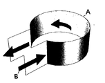
- the magnetron cavity (A) has a circular region connected to a planar region.
- the electrical current flows on the sides of the cavity shown by the arrows (B). In this case, there is only one turn per height of the cavity times the volume of the cavity times the permeability which produces the inductance.
- the two planar regions produce a capacitance across the ends which creates the resonant frequency.
- the differential of the magnetic energy would be a force. So there has to be a gradient of the surface inductance.
- the volume element of a groove is equal to the circumferential length times the height times the width of the groove. The easiest is to vary the height with radius. Since the curvature is negative, the gradient has to be negative as well in order to get a positive lift force. Thus the height goes from large to small from the inside to the outside radius.
- the invention relates to a spacecraft with a domed, circular hull of elliptical cross-section having dual electrically-charged counter-rotating rotors located one above the other on the edge of the hull.
- the upper rotor is positively charged and rotates clockwise with a negative angular velocity per the right-hand rule.
- the lower rotor is negatively charged and rotates with a positive angular velocity.
- the current density is the surface charge density times the velocity of the rotor. This particular combination of velocity and charge produces an angular momentum which creates a negative spiking spacetime curvature over the rotors.
- the top surface of the rotor is etched or machined with circular grooves around the rotor. This creates a surface inductance which is equal to the permeability of space times the turns per length squared times the volume of the groove. In this case, there is only one turn per height of the groove. If the height of the groove decreases from one groove to the next, then there is a negative surface inductance gradient in the radial direction. So the lift force on the rotors would be the negative surface inductance gradient times the negative spacetime curvature times the current density squared times the rotor area squared.
- FIG. 1 Perspective of magnetron cavity.
- FIG. 2 Spacetime curvature G zz over hull and rotor.
- FIG. 3 Perspective view of spacecraft with dual rotors.
- FIG. 4 Wire frame view of three solenoids.
- FIG. 5 Vector potential equation for solenoid.
- FIG. 6 Units of vector potential.
- FIG. 7. 3D graph of vector potential using three solenoids.
- FIG. 8 Perspective of vector potential along rotors.
- FIG. 9 Rotor mechanics diagram using exponential representation.
- FIG. 10 Angular momentum equation due to vector potential and rotating charged rotors.
- FIG. 11 Units of angular momentum.
- FIG. 12 Exponential equation for twice imaginary sine of the angle.
- FIG. 13 Angular momentum equation for g metric tensor.
- FIG. 14 Angular momentum term for elemental line length ds 2 .
- FIG. 15 The g metric tensor containing the angular momentum.
- FIG. 16 The spacetime curvature tension G zz versus radius due to angular momentum.
- FIG. 17 Magnetic energy equation.
- FIG. 18 Units of magnetic energy.
- FIG. 19 Cross-section of rotor showing groove height gradient.
- FIG. 20 Equation for the height h of the rotor groove as a function of radius.
- FIG. 21 Equation for the groove inductance gradient.
- FIG. 22 Plot of the groove inductance gradient as a function of radius showing that it is negative at the rotor.
- FIG. 23 Lift force on rotors due to inductance gradient, compression curvature, rotor current density and area.
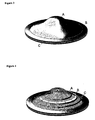
- the spacecraft has a circular, domed hull of elliptical cross-section with dual electrically-charged counter-rotating rotors one above the other on the edge of the hull.
- the vector potential ⁇ A ⁇ of a solenoid is equal to the number of turns per length ⁇ n ⁇ times the current ⁇ I ⁇ times the radius of the solenoid ⁇ a ⁇ squared divided by half the permittivity of space ⁇ 0 ⁇ times the speed of light ⁇ c ⁇ squared times the radius ⁇ r′ ⁇ prime from the center of the coil to some location in space such as the rotors. It has been found by physicists Bohm and Aharanov that the vector potential field is not confined to an infinitely long solenoid as is the magnetic B field. The vector potential has units of kilogram-meter per second-coulomb as seen in FIG. 6.
- This graph is then rotated ninety degrees so that it can be located in relation to the rotors as seen in FIG. 8.
- the vector potential (D) which is created by solenoids (A,B,C), passes through rotors (E) and (H).
- rotor mechanics uses the exponential function for the harmonic motion of the rotor.
- the radius is ⁇ r e i ⁇ t ⁇ which when differentiated with respect to time becomes a velocity ⁇ i ⁇ r e i ⁇ t ⁇ where the imaginary ⁇ i ⁇ is a 90° phase lead which makes the velocity tangential to the rotor.
- the rotor surface charge ⁇ sigma ⁇ is rotating around at some radius ⁇ r ⁇ .
- the surface charge density is positive (+ ⁇ but the rotor has a negative angular velocity ⁇ .
- the surface charge density is negative ⁇ but the rotor has a positive angular velocity ⁇ + ⁇ . So the combined surface charge rotation is ⁇ r e i ⁇ t + ⁇ r e ⁇ i ⁇ t ⁇ .
- This charge rotation times the positive vector potential due to the solenoids times the rotor surface area is equal to angular momentum S as shown in FIG. 10.
- the units are given in FIG. 11.
- the angular momentum is equal to the negative of the difference of the exponentials times a constant. I then recalled that this difference is equal to twice imaginary sine of the angle as shown in FIG. 12.
- the angular momentum is equal to minus two times the imaginary number times a constant times the sine of the rotational angle.
- the electromagnetic fields determine the flow rate of angular momentum.
- the angular momentum becomes imaginary.
- the angular momentum is imaginary due directly to the rotors. The importance of being imaginary is that the radius resonates with the angular momentum.
- the denominator has a term equal to the radius to the fourth power plus twice the square of the angular momentum.
- angular momentum is viewed as meter squared. So the square of imaginary angular momentum is negative angular momentum equal to negative meters to the fourth power. So at some radius, these two terms are equal, the denominator goes to zero, and the spacetime curvature becomes infinitely-large, creating a huge spike.
- the elemental length ds 2 is curved by the presence of the angular momentum which is one of the energies, such as mass, charge, and electromagnetic fields, that Einstein showed can curve spacetime. Because the angular momentum is pointing in the vertical z-direction, due to the direction of the unit normal vector to the surface of the rotor, it rotates around in the angular direction ⁇ dtd ⁇ as found in cylindrical coordinates ⁇ t,r, ⁇ ,z ⁇ .
- g metric tensor which is a measure of length in spacetime coordinates. It is a 4 by 4 matrix with rows and columns equal to the cylindrical coordinates. Referring to FIG. 15, the diagonal of the matrix is ⁇ 1,1,r 2 ,1 ⁇ where the minus one corresponds to time which is Einstein's convention. Half the angular momentum goes in the ⁇ t ⁇ slot of the g metric tensor, and the other half goes in the ⁇ t ⁇ slot.
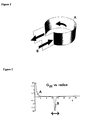
- the curvature has a large positive spike over the dome of the hull (A) which means that there is a large lift force over the center of the hull.
- the curvature then falls off and spikes with a negative spacetime curvature compression over the rotors (B).
- This curvature also oscillates back and forth a short distance due to the sinusoidal term. The problem is to convert this compression into a lift force which this invention solves.
- inductance of a solenoid is equal to the permeability of space times the number of wire turns per length squared times the volume of the solenoid.
- the electrical current (B) flows around the height of the strip (A), so there is only one turn per the height. Then that is multiplied by the volume of the cavity and permeability to get the inductance.
- the inductor is storing magnetic energy equal to half the inductance times the current squared. In this invention, current density J in amp per meter is used rather than current.
- the magnetic energy would have to be related to the inductance times the square of the current density times the area squared of the rotor and times the negative spacetime curvature.
- the curvature is measured in inverse meter squared. That product produces a negative magnetic energy when in fact I want a positive force.
- FIG. 20 gives the equation for the height of the groove along the radius of the rotor.
- FIG. 21 gives the inductance gradient by differentiating the inductance with respect to the radius.
- the initial groove height ho is not very large, and the inductance gradient becomes negative at the rotor as seen in the graph of FIG. 22.
Landscapes
- Engineering & Computer Science (AREA)
- Chemical & Material Sciences (AREA)
- Combustion & Propulsion (AREA)
- Aviation & Aerospace Engineering (AREA)
- Physics & Mathematics (AREA)
- General Engineering & Computer Science (AREA)
- Spectroscopy & Molecular Physics (AREA)
- High Energy & Nuclear Physics (AREA)
- Mechanical Engineering (AREA)
- Remote Sensing (AREA)
- Electromagnets (AREA)
Abstract
The invention is a spacecraft having a circular, domed hull around which dual electrically-charged rotors one above the other are counter-rotating on the edge of the hull. Embedded in the hull are three solenoids which create a positive vector potential at the rotors. The surface charge density times the radius times the vector potential times the area of the rotors creates an angular momentum in the vertical direction. This angular momentum produces a positive spacetime curvature over the dome of the hull and a negative spiking spacetime compression over the rotors. By machining circumferential grooves of decreasing height along the radius of the rotor, a negative surface inductance is generated. This negative inductance gradient times the negative spacetime compression time the rotor current density squared times the rotor area squared is a positive lift force on the spacecraft.
Description
- The invention, which is the object of my present application, is a spacecraft with a circular, domed hull around which are located dual electrically-charged counter-rotating rotors. The top surface of the upper rotor is etched with circular metallic grooves which give the rotor a surface inductance. The groove height decreases from the inside radius to the outside radius of the rotor giving it a radial inductance gradient. The surface charge density times the angular velocity produces a current density. The counter-rotating rotors produce a negative spacetime curvature over the rotors. The negative surface inductance gradient times the negative spiking spacetime curvature times the current density squared times the area squared is the positive lift force on the rotor.
- Gravitation, Wheeler
- Traveling-Wave Tubes, The Bell System Technical Journal, Vol. XXIX, January 1950, No. 1, J. R. Pierce.
- The Magnetron as a Generator of Centimeter Waves, The Bell System Technical Journal, Vol. XXV, April 1946, No. 2, J. B. Fisk, H. D. Hagstrum, P. L. Hartman.
- Lectures on Physics, Richard Feynman
- Geometry of Electromagnetism, Paul Hammond
- I was reading several articles about the development of the magnetron during World War II in the Bell System Technical Journal. I was trying to understand why the device resonates because it must contain a spring constant which would arise from an inductance and capacitance due to the geometry of the cavity. As given by Feynman, inductance of a solenoid is the permeability of space times the turns per length squared times the volume of the solenoid. Referring to FIG. 1, the magnetron cavity (A) has a circular region connected to a planar region. The electrical current flows on the sides of the cavity shown by the arrows (B). In this case, there is only one turn per height of the cavity times the volume of the cavity times the permeability which produces the inductance. The two planar regions produce a capacitance across the ends which creates the resonant frequency.
- From my previous patent application Dual Rotor Propulsion System I know that the two rotors produce a current density in the angular direction along the rotor. If I spread out the magnetron cavity into a circular groove around a rotor, then the current would flow on the side walls enclosing the groove volume. The rotors also produce a spacetime curvature profile as shown in FIG. 2. Curve (A) is a positive spacetime curvature tension over the dome. Curve (B) is a negative spiking spacetime curvature over the rotors. The curvature is measured in inverse meter squared. So the surface inductance times the negative curvature times the current density squared times the rotor area squared is magnetic energy. The differential of the magnetic energy would be a force. So there has to be a gradient of the surface inductance. The volume element of a groove is equal to the circumferential length times the height times the width of the groove. The easiest is to vary the height with radius. Since the curvature is negative, the gradient has to be negative as well in order to get a positive lift force. Thus the height goes from large to small from the inside to the outside radius.
- The invention relates to a spacecraft with a domed, circular hull of elliptical cross-section having dual electrically-charged counter-rotating rotors located one above the other on the edge of the hull. The upper rotor is positively charged and rotates clockwise with a negative angular velocity per the right-hand rule. The lower rotor is negatively charged and rotates with a positive angular velocity. The current density is the surface charge density times the velocity of the rotor. This particular combination of velocity and charge produces an angular momentum which creates a negative spiking spacetime curvature over the rotors.
- The top surface of the rotor is etched or machined with circular grooves around the rotor. This creates a surface inductance which is equal to the permeability of space times the turns per length squared times the volume of the groove. In this case, there is only one turn per height of the groove. If the height of the groove decreases from one groove to the next, then there is a negative surface inductance gradient in the radial direction. So the lift force on the rotors would be the negative surface inductance gradient times the negative spacetime curvature times the current density squared times the rotor area squared.
- Not Applicable.
- FIG. 1. Perspective of magnetron cavity.
- FIG. 2. Spacetime curvature G zz over hull and rotor.
- FIG. 3. Perspective view of spacecraft with dual rotors.
- FIG. 4. Wire frame view of three solenoids.
- FIG. 5. Vector potential equation for solenoid.
- FIG. 6. Units of vector potential.
- FIG. 7. 3D graph of vector potential using three solenoids.
- FIG. 8. Perspective of vector potential along rotors.
- FIG. 9. Rotor mechanics diagram using exponential representation.
- FIG. 10. Angular momentum equation due to vector potential and rotating charged rotors.
- FIG. 11. Units of angular momentum.
- FIG. 12. Exponential equation for twice imaginary sine of the angle.
- FIG. 13. Angular momentum equation for g metric tensor.
- FIG. 14. Angular momentum term for elemental line length ds 2.
- FIG. 15. The g metric tensor containing the angular momentum.
- FIG. 16. The spacetime curvature tension G zz versus radius due to angular momentum.
- FIG. 17. Magnetic energy equation.
- FIG. 18. Units of magnetic energy.
- FIG. 19. Cross-section of rotor showing groove height gradient.
- FIG. 20. Equation for the height h of the rotor groove as a function of radius.
- FIG. 21. Equation for the groove inductance gradient.
- FIG. 22. Plot of the groove inductance gradient as a function of radius showing that it is negative at the rotor.
- FIG. 23. Lift force on rotors due to inductance gradient, compression curvature, rotor current density and area.
- 1. Referring to FIG. 3, the spacecraft has a circular, domed hull of elliptical cross-section with dual electrically-charged counter-rotating rotors one above the other on the edge of the hull.
- 2. Referring to FIG. 4, embedded within the hull are three solenoids or current loops carrying a constant electrical current in the positive sense per the right-hand rule.
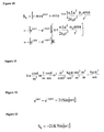
- 3. Referring to FIG. 5, Feynman has shown that the vector potential {A} of a solenoid is equal to the number of turns per length {n} times the current {I} times the radius of the solenoid {a} squared divided by half the permittivity of space {ε 0} times the speed of light {c} squared times the radius {r′} prime from the center of the coil to some location in space such as the rotors. It has been found by physicists Bohm and Aharanov that the vector potential field is not confined to an infinitely long solenoid as is the magnetic B field. The vector potential has units of kilogram-meter per second-coulomb as seen in FIG. 6.
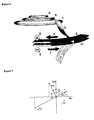
- 4. Referring to FIG. 7, the three solenoids of varying radius and area produce a positive vector potential at the centerline of the rotors as seen in the graph.
- 5. This graph is then rotated ninety degrees so that it can be located in relation to the rotors as seen in FIG. 8. The vector potential (D), which is created by solenoids (A,B,C), passes through rotors (E) and (H). Rotor (E), which has a positive charge (G), is rotating clockwise (F), and rotor (H), which has a negative charge (K), is rotating counter-clockwise (J).
- 6. Referring to FIG. 9, rotor mechanics uses the exponential function for the harmonic motion of the rotor. The radius is {r e iωt} which when differentiated with respect to time becomes a velocity {i ω r eiωt} where the imaginary {i} is a 90° phase lead which makes the velocity tangential to the rotor.
- 7. The rotor surface charge {σ sigma} is rotating around at some radius {r}. For the upper rotor the surface charge density is positive (+σ} but the rotor has a negative angular velocity {−ω}. For the lower rotor, the surface charge density is negative {−σ} but the rotor has a positive angular velocity {+ω}. So the combined surface charge rotation is {−σ r e iωt+σ r e−iωt}. This charge rotation times the positive vector potential due to the solenoids times the rotor surface area is equal to angular momentum S as shown in FIG. 10. The units are given in FIG. 11. The angular momentum is equal to the negative of the difference of the exponentials times a constant. I then recalled that this difference is equal to twice imaginary sine of the angle as shown in FIG. 12.
- 8. Referring to FIG. 13, the angular momentum is equal to minus two times the imaginary number times a constant times the sine of the rotational angle. In most of my spacecraft designs, the electromagnetic fields determine the flow rate of angular momentum. When the flow rate is integrated with respect to time, the angular momentum becomes imaginary. In this invention, the angular momentum is imaginary due directly to the rotors. The importance of being imaginary is that the radius resonates with the angular momentum. In some spacetime curvature equations, the denominator has a term equal to the radius to the fourth power plus twice the square of the angular momentum. In spacetime units, angular momentum is viewed as meter squared. So the square of imaginary angular momentum is negative angular momentum equal to negative meters to the fourth power. So at some radius, these two terms are equal, the denominator goes to zero, and the spacetime curvature becomes infinitely-large, creating a huge spike.
- 9. This next section calculates the spacetime curvature from the equation for the angular momentum.
- 10. Referring to FIG. 14, the elemental length ds 2 is curved by the presence of the angular momentum which is one of the energies, such as mass, charge, and electromagnetic fields, that Einstein showed can curve spacetime. Because the angular momentum is pointing in the vertical z-direction, due to the direction of the unit normal vector to the surface of the rotor, it rotates around in the angular direction {dtdθ} as found in cylindrical coordinates {t,r,θ,z}.
- 11. In gravitational physics there is a g metric tensor which is a measure of length in spacetime coordinates. It is a 4 by 4 matrix with rows and columns equal to the cylindrical coordinates. Referring to FIG. 15, the diagonal of the matrix is {−1,1,r 2,1} where the minus one corresponds to time which is Einstein's convention. Half the angular momentum goes in the {tθ} slot of the g metric tensor, and the other half goes in the {θt} slot.
- 12. From this g metric tensor, Einstein's G curvature tensor can be calculated in the various directions. In Einstein's General Theory of Relativity, his equation is G=8πT where G is the spacetime curvature measured in inverse meter squared, and the T tensor is the stress-energy-momentum matrix containing all the electromagnetic pressures, mass and momentum components that curve spacetime. The spacetime curvature tension G zz in the vertical direction, as a function of radius, is shown in FIG. 16. A positive curvature indicates that there is a spacetime tension over the hull which produces lift. The curvature has a large positive spike over the dome of the hull (A) which means that there is a large lift force over the center of the hull. The curvature then falls off and spikes with a negative spacetime curvature compression over the rotors (B). This curvature also oscillates back and forth a short distance due to the sinusoidal term. The problem is to convert this compression into a lift force which this invention solves.
- 13. This next section shows how the spacetime compression over the rotors generates lift.
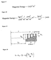
- 14. As I mentioned, I have been reading some of the World War II magnetron scientific papers of the Bell System Technical Journal. It turns out that inductance of a solenoid is equal to the permeability of space times the number of wire turns per length squared times the volume of the solenoid. Imagine having a copper strip in the shape of the magnetron cavity in FIG. 1. The electrical current (B) flows around the height of the strip (A), so there is only one turn per the height. Then that is multiplied by the volume of the cavity and permeability to get the inductance. The inductor is storing magnetic energy equal to half the inductance times the current squared. In this invention, current density J in amp per meter is used rather than current. So taking a hint from this information, the magnetic energy would have to be related to the inductance times the square of the current density times the area squared of the rotor and times the negative spacetime curvature. The curvature is measured in inverse meter squared. That product produces a negative magnetic energy when in fact I want a positive force. This means that there has to be an inductance gradient in the equation instead of pure inductance and, furthermore, the gradient has to be negative in order to cancel out the negative sign of the compression curvature.
- 15. The equation for the magnetic energy in terms of the inductance {}, curvature {K}, current density {J} and area {A} is shown in FIG. 17 with the units in FIG. 18. The inductance in the equation is proportional to the volume of the circular groove in the top surface of the rotor. That volume is equal to {2π r h w} where {h] is the height of groove (depth) and {w} is the width located at some radius {r}. In terms of machining, it would be more difficult to machine a variable width groove rather than a deeper groove of a constant width. So I am going to say the gradient is in the radial direction with the height of the groove decreasing going from the inside radius to the outside radius as depicted in FIG. 19.

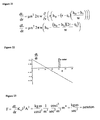
- 16. FIG. 20 gives the equation for the height of the groove along the radius of the rotor.
- 17. FIG. 21 gives the inductance gradient by differentiating the inductance with respect to the radius. The initial groove height ho is not very large, and the inductance gradient becomes negative at the rotor as seen in the graph of FIG. 22.
- 18. Referring to FIG. 23, the lift force on the rotor is now positive due to the combined negative inductance gradient times the negative spacetime compression. The square of the negative current density is positive also. This means that that the top surface of the lower rotor can also have a surface inductance gradient which would double the lift force.
Claims (9)
1. A spacecraft having a circular, domed hull with dual electrically-charged counter-rotating rotors one above the other located on the edge of hull.
2. Said hull having embedded within it three or more solenoids which generate a positive vector potential at the rotors.
3. Said upper rotor having a positive surface charge density, and rotating clockwise in the negative direction per the right-hand rule.
4. Said lower rotor having a negative surface charge density, and rotating counterclockwise in the positive direction per the right-hand rule.
5. Said rotor surface charge density and velocity creating a negative current density on both rotors.
6. Said vector potential and rotating surface charge density on rotors generating an angular momentum in the vertical direction.
7. Said angular momentum, generating a spacetime curvature tension over the dome of the hull, and a negative oscillating spacetime curvature compression over the rotors.
8. Said rotors having circumferential grooves of decreasing height machined into the top surface of the rotors in order to create a negative surface inductance gradient.
9. Said negative surface inductance gradient times the negative spacetime curvature compression times the rotor current density squared times the rotor area squared generating a positive lift force on the spacecraft.
Priority Applications (1)
| Application Number | Priority Date | Filing Date | Title |
|---|---|---|---|
| US10/170,847 US20030230675A1 (en) | 2002-06-12 | 2002-06-12 | Rotor inductance propulsion system |
Applications Claiming Priority (1)
| Application Number | Priority Date | Filing Date | Title |
|---|---|---|---|
| US10/170,847 US20030230675A1 (en) | 2002-06-12 | 2002-06-12 | Rotor inductance propulsion system |
Publications (1)
| Publication Number | Publication Date |
|---|---|
| US20030230675A1 true US20030230675A1 (en) | 2003-12-18 |
Family
ID=29732607
Family Applications (1)
| Application Number | Title | Priority Date | Filing Date |
|---|---|---|---|
| US10/170,847 Abandoned US20030230675A1 (en) | 2002-06-12 | 2002-06-12 | Rotor inductance propulsion system |
Country Status (1)
| Country | Link |
|---|---|
| US (1) | US20030230675A1 (en) |
Cited By (2)
| Publication number | Priority date | Publication date | Assignee | Title |
|---|---|---|---|---|
| US20070295010A1 (en) * | 2006-06-27 | 2007-12-27 | Varim Technologies Inc. | Method and apparatus to generate thrust by inertial mass variance |
| US8143738B2 (en) | 2008-08-06 | 2012-03-27 | Infinite Wind Energy LLC | Hyper-surface wind generator |
-
2002
- 2002-06-12 US US10/170,847 patent/US20030230675A1/en not_active Abandoned
Cited By (2)
| Publication number | Priority date | Publication date | Assignee | Title |
|---|---|---|---|---|
| US20070295010A1 (en) * | 2006-06-27 | 2007-12-27 | Varim Technologies Inc. | Method and apparatus to generate thrust by inertial mass variance |
| US8143738B2 (en) | 2008-08-06 | 2012-03-27 | Infinite Wind Energy LLC | Hyper-surface wind generator |
Similar Documents
| Publication | Publication Date | Title |
|---|---|---|
| Vishveshwara | Scattering of gravitational radiation by a Schwarzschild black-hole | |
| Branover | Turbulence and structures: chaos, fluctuations, and helical self-organization in nature and the laboratory | |
| US20120137652A1 (en) | Electromagnetic Thrust System | |
| Yadav et al. | Dark matter as scalaron in f (R) gravity models | |
| Krugel | An introduction to the physics of interstellar dust | |
| Milosavljević et al. | Weibel filament decay and thermalization in collisionless shocks and gamma-ray burst afterglows | |
| Wysin | Magnetic Excitations and Geometric Confinement | |
| Adams et al. | ã и d vx | |
| Youngquist et al. | Alternating magnetic field forces for satellite formation flying | |
| Al Rsheed et al. | Rotating optical tubes for vertical transport of atoms | |
| Burinskii | Stability of the lepton bag model based on the Kerr–Newman solution | |
| US20030230675A1 (en) | Rotor inductance propulsion system | |
| Davidson et al. | Are planetary dynamos driven by helical waves? | |
| Malova et al. | Structure of current sheets with quasi-adiabatic dynamics of particles in the solar wind | |
| Fischer-Cripps | The materials physics companion | |
| US20080287301A1 (en) | Method and apparatus for generation of a gravitational force on a rotating body such as a superconductor | |
| US20060168937A1 (en) | Magnetic monopole spacecraft | |
| Power et al. | Electromagnetic fields of a moving electric dipole | |
| Kruusen | Quantum gravity and the creation of wormholes | |
| US20230121805A1 (en) | System and method for generating forces using asymmetrical electrostatic pressure | |
| Coleman Jr | Electric currents in the solar wind | |
| Mashhoon | The hypothesis of locality and its limitations | |
| NICOARĂ et al. | Problems and Applications of PHYSICS for Students of Engineering | |
| Burinskii | New Path to Unification of Gravity with Particle Physics | |
| Gailitis et al. | Dynamo experiments |
Legal Events
| Date | Code | Title | Description |
|---|---|---|---|
| STCB | Information on status: application discontinuation |
Free format text: ABANDONED -- FAILURE TO RESPOND TO AN OFFICE ACTION |