US20030196441A1 - Cascaded thermoacoustic devices - Google Patents
Cascaded thermoacoustic devices Download PDFInfo
- Publication number
- US20030196441A1 US20030196441A1 US10/125,268 US12526802A US2003196441A1 US 20030196441 A1 US20030196441 A1 US 20030196441A1 US 12526802 A US12526802 A US 12526802A US 2003196441 A1 US2003196441 A1 US 2003196441A1
- Authority
- US
- United States
- Prior art keywords
- units
- regenerator
- thermoacoustic
- stack
- high specific
- Prior art date
- Legal status (The legal status is an assumption and is not a legal conclusion. Google has not performed a legal analysis and makes no representation as to the accuracy of the status listed.)
- Granted
Links
Images


Classifications
-
- F—MECHANICAL ENGINEERING; LIGHTING; HEATING; WEAPONS; BLASTING
- F02—COMBUSTION ENGINES; HOT-GAS OR COMBUSTION-PRODUCT ENGINE PLANTS
- F02G—HOT GAS OR COMBUSTION-PRODUCT POSITIVE-DISPLACEMENT ENGINE PLANTS; USE OF WASTE HEAT OF COMBUSTION ENGINES; NOT OTHERWISE PROVIDED FOR
- F02G1/00—Hot gas positive-displacement engine plants
- F02G1/04—Hot gas positive-displacement engine plants of closed-cycle type
- F02G1/043—Hot gas positive-displacement engine plants of closed-cycle type the engine being operated by expansion and contraction of a mass of working gas which is heated and cooled in one of a plurality of constantly communicating expansible chambers, e.g. Stirling cycle type engines
- F02G1/0435—Hot gas positive-displacement engine plants of closed-cycle type the engine being operated by expansion and contraction of a mass of working gas which is heated and cooled in one of a plurality of constantly communicating expansible chambers, e.g. Stirling cycle type engines the engine being of the free piston type
-
- F—MECHANICAL ENGINEERING; LIGHTING; HEATING; WEAPONS; BLASTING
- F25—REFRIGERATION OR COOLING; COMBINED HEATING AND REFRIGERATION SYSTEMS; HEAT PUMP SYSTEMS; MANUFACTURE OR STORAGE OF ICE; LIQUEFACTION SOLIDIFICATION OF GASES
- F25B—REFRIGERATION MACHINES, PLANTS OR SYSTEMS; COMBINED HEATING AND REFRIGERATION SYSTEMS; HEAT PUMP SYSTEMS
- F25B9/00—Compression machines, plants or systems, in which the refrigerant is air or other gas of low boiling point
- F25B9/14—Compression machines, plants or systems, in which the refrigerant is air or other gas of low boiling point characterised by the cycle used, e.g. Stirling cycle
- F25B9/145—Compression machines, plants or systems, in which the refrigerant is air or other gas of low boiling point characterised by the cycle used, e.g. Stirling cycle pulse-tube cycle
-
- F—MECHANICAL ENGINEERING; LIGHTING; HEATING; WEAPONS; BLASTING
- F02—COMBUSTION ENGINES; HOT-GAS OR COMBUSTION-PRODUCT ENGINE PLANTS
- F02G—HOT GAS OR COMBUSTION-PRODUCT POSITIVE-DISPLACEMENT ENGINE PLANTS; USE OF WASTE HEAT OF COMBUSTION ENGINES; NOT OTHERWISE PROVIDED FOR
- F02G2243/00—Stirling type engines having closed regenerative thermodynamic cycles with flow controlled by volume changes
- F02G2243/30—Stirling type engines having closed regenerative thermodynamic cycles with flow controlled by volume changes having their pistons and displacers each in separate cylinders
- F02G2243/50—Stirling type engines having closed regenerative thermodynamic cycles with flow controlled by volume changes having their pistons and displacers each in separate cylinders having resonance tubes
- F02G2243/54—Stirling type engines having closed regenerative thermodynamic cycles with flow controlled by volume changes having their pistons and displacers each in separate cylinders having resonance tubes thermo-acoustic
-
- F—MECHANICAL ENGINEERING; LIGHTING; HEATING; WEAPONS; BLASTING
- F25—REFRIGERATION OR COOLING; COMBINED HEATING AND REFRIGERATION SYSTEMS; HEAT PUMP SYSTEMS; MANUFACTURE OR STORAGE OF ICE; LIQUEFACTION SOLIDIFICATION OF GASES
- F25B—REFRIGERATION MACHINES, PLANTS OR SYSTEMS; COMBINED HEATING AND REFRIGERATION SYSTEMS; HEAT PUMP SYSTEMS
- F25B2309/00—Gas cycle refrigeration machines
- F25B2309/14—Compression machines, plants or systems characterised by the cycle used
- F25B2309/1402—Pulse-tube cycles with acoustic driver
-
- F—MECHANICAL ENGINEERING; LIGHTING; HEATING; WEAPONS; BLASTING
- F25—REFRIGERATION OR COOLING; COMBINED HEATING AND REFRIGERATION SYSTEMS; HEAT PUMP SYSTEMS; MANUFACTURE OR STORAGE OF ICE; LIQUEFACTION SOLIDIFICATION OF GASES
- F25B—REFRIGERATION MACHINES, PLANTS OR SYSTEMS; COMBINED HEATING AND REFRIGERATION SYSTEMS; HEAT PUMP SYSTEMS
- F25B2309/00—Gas cycle refrigeration machines
- F25B2309/14—Compression machines, plants or systems characterised by the cycle used
- F25B2309/1407—Pulse-tube cycles with pulse tube having in-line geometrical arrangements
Definitions
- Proper design of the acoustic network causes the gas in the pores of regenerator 48 to move toward hot heat exchanger 44 while the pressure is high and toward main ambient heat exchanger 46 while the pressure is low.
- the oscillating thermal expansion and contraction of the gas in regenerator 48 attending its oscillating motion along the temperature gradient in the pores, is therefore temporally phased with respect to the oscillating pressure so that the thermal expansion occurs while the pressure is high and the thermal contraction occurs while the pressure is low.
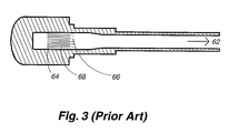
- FIG. 3 shows a standing-wave thermoacoustic engine delivering acoustic power to an unspecified load 62 to the right.
- the standing-wave thermoacoustic engine creates acoustic power from heat in a somewhat different way than do regenerator-based engines such as those shown in FIGS. 1 and 2.
- High-temperature heat such as from a flame, from nuclear fuel, or from ohmic heating, is added to the standing-wave thermoacoustic engine at hot heat exchanger 64 , ambient-temperature waste heat is removed from the engine at the ambient heat exchanger 66 , and oscillations of the gas are thereby encouraged.
- thermoacoustic-Stirling hybrid refrigerators can suffer from dramatic instability with respect to Gedeon streaming, so that an adjustable jet pump 50 would require continuous feedback-controlled adjustment.
- the stack-based standing-wave thermoacoustic engine (FIG. 3) is reliable and costs little to fabricate, but its efficiency is only about 2 ⁇ 3 that of the regenerator-based systems.
Landscapes
- Engineering & Computer Science (AREA)
- Mechanical Engineering (AREA)
- General Engineering & Computer Science (AREA)
- Chemical & Material Sciences (AREA)
- Combustion & Propulsion (AREA)
- Physics & Mathematics (AREA)
- Thermal Sciences (AREA)
- Soundproofing, Sound Blocking, And Sound Damping (AREA)
- Devices That Are Associated With Refrigeration Equipment (AREA)
Abstract
Description
- [0001] This invention was made with government support under Contract No. W7405-ENG-36 awarded by the U.S. Department of Energy. The government has certain rights in the invention.
- The present invention relates generally to oscillating wave engines and refrigerators, and, more particularly, to thermoacoustic engines and refrigerators, including Stirling engines and refrigerators and their hybrids.
- According to thermodynamic principles, acoustic power in a gas—a nonzero time average product of oscillating pressure and oscillating volume flow rate—is as valuable as other forms of work such as electrical power, rotating shaft power, and hydraulic power. For example, acoustic power can be used to produce refrigeration, such as in orifice pulse tube refrigerators; it can be used to produce electricity, via linear alternators; and it can be used to generate rotating shaft power, e.g., with a Wells turbine. Furthermore, acoustic power can be created from heat in a variety of heat engines such as Stirling engines and thermoacoustic engines.
- Historically, Stirling's hot-air engine of the early 19th century was the first heat engine to use oscillating pressure and oscillating volume flow rate in a gas in a sealed system, although the time-averaged product thereof was not called acoustic power. Since then, a variety of related engines and refrigerators have been developed, including Stirling refrigerators, Ericsson engines, orifice pulse-tube refrigerators, standing-wave thermoacoustic engines and refrigerators, free-piston Stirling engines and refrigerators, and thermoacoustic-Stirling hybrid engines and refrigerators. Combinations thereof, such as the Vuilleumier refrigerator and the thermoacoustically driven orifice pulse tube refrigerator, have provided heat-driven refrigeration.
- Much of the evolution of this entire family of acoustic-power thermodynamic technologies has been driven by the search for higher efficiencies, greater reliabilities, and lower fabrication costs. FIGS. 1, 2, and 3 show some prior art engine examples.
- FIG. 1 shows a free-piston Stirling
engine 10 integrated with alinear alternator 12 to form a heat-driven electric generator. High-temperature heat, such as from a flame or from nuclear fuel, is added to the engine at thehot heat exchanger 14, ambient-temperature waste heat is removed from the engine at theambient heat exchanger 16, and oscillations of thegas 18,piston 22, and displacer 24 are thereby encouraged. The oscillations ofpiston 22 causepermanent magnet 26 to oscillate throughwire coil 28, thereby generating electrical power which is removed from the engine to be used elsewhere. - The conversion of heat to acoustic power occurs in
regenerator 32, which is a solid matrix smoothly spanning the temperature difference betweenhot heat exchanger 14 andambient heat exchanger 16 and containing small pores through which the gas oscillates. The pores must be small enough that the gas in them is in excellent local thermal contact with the solid matrix. Proper design of the dynamics of movingpiston 22 and displacer 24, theirgas springs 34/36, andgas 18 throughout the system causes the gas in the pores ofregenerator 32 to move towardhot heat exchanger 14 while the pressure is high and towardambient heat exchanger 16 while the pressure is low. The oscillating thermal expansion and contraction of the gas inregenerator 32, attending its oscillating motion along the temperature gradient in the pores, is therefore temporally phased with respect to the oscillating pressure so that the thermal expansion occurs while the pressure is high and the thermal contraction occurs while the pressure is low. - Those skilled in the art understand that another way to view the operation of the free-piston Stirling engine, and indeed all regenerator-based engines including all Stirling and traveling-wave engines, is that acoustic power flows into the ambient end of the regenerator, is amplified in the regenerator by a temperature gradient in the regenerator, and flows out of the hot end of the regenerator. Ideally, the heat exchangers at the ends of the regenerator are essentially transparent to this acoustic power flow. Ideally, the acoustic-power amplification factor in the regenerator is equal to the ratio of hot temperature to ambient temperature, both temperatures being measured in absolute units such as Kelvin.
- In the free piston Stirling engine of FIG. 1, the acoustic power flowing out of the hot end of
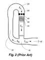
regenerator 32 is absorbed from the gas by the hot end ofdisplacer 24 and immediately delivered to the gas at the opposite end of displacer 24. There, some of the acoustic power flows into the ambient end ofregenerator 32 to provide the original acoustic power for amplification, and the rest is delivered bygas 18 topiston 22. Hence, circulating acoustic power flows through the regenerator from ambient to hot temperatures and is amplified therein. - FIG. 2 shows another regenerator-based engine: a thermoacoustic-Stirling hybrid engine delivering acoustic power to an unspecified load 42 (e.g., a linear alternator or any of the aforementioned refrigerators) to the right. High-temperature heat, such as from a flame, from nuclear fuel, or from ohmic heating, is added to the engine at
hot heat exchanger 44, most of the ambient-temperature waste heat is removed from the engine at mainambient heat exchanger 46, and oscillations of the gas are thereby encouraged. The conversion of heat to acoustic power occurs inregenerator 48, which is structurally and functionally identical to that described in FIG. 1 for the free piston Stirling engine. Proper design of the acoustic network (including, principally, thefeedback inertance 52 and compliance 54) causes the gas in the pores ofregenerator 48 to move towardhot heat exchanger 44 while the pressure is high and toward mainambient heat exchanger 46 while the pressure is low. The oscillating thermal expansion and contraction of the gas inregenerator 48, attending its oscillating motion along the temperature gradient in the pores, is therefore temporally phased with respect to the oscillating pressure so that the thermal expansion occurs while the pressure is high and the thermal contraction occurs while the pressure is low. - As in the free piston Stirling engine, another way to view the operation of the thermoacoustic-Stirling hybrid engine is that acoustic power EC flows into the ambient end of
regenerator 48, is amplified by the temperature gradient inregenerator 48, and flows out of the hot end ofregenerator 48. In FIG. 2, the acoustic power {dot over (E)}H flowing out of the hot end of the regenerator splits into two portions {dot over (E)}fb and {dot over (E)}res at theresonator junction 40, with the required amount {dot over (E)}C flowing into the ambient end ofregenerator 48 to provide the original acoustic power for amplification, and the rest {dot over (E)}res being delivered to the right to theunspecified load 42. Hence, again, circulating acoustic power flows throughregenerator 42 from ambient to hot and is amplified therein. - FIG. 3 shows a standing-wave thermoacoustic engine delivering acoustic power to an
unspecified load 62 to the right. The standing-wave thermoacoustic engine creates acoustic power from heat in a somewhat different way than do regenerator-based engines such as those shown in FIGS. 1 and 2. High-temperature heat, such as from a flame, from nuclear fuel, or from ohmic heating, is added to the standing-wave thermoacoustic engine athot heat exchanger 64, ambient-temperature waste heat is removed from the engine at theambient heat exchanger 66, and oscillations of the gas are thereby encouraged. The conversion of heat to acoustic power occurs instack 68, which is a solid matrix smoothly spanning the temperature difference betweenhot heat exchanger 64 andambient heat exchanger 66 and containing pores through which the gas oscillates. The pores instack 68 must be significantly larger than those in a regenerator operating under similar conditions, because excellent local thermal contact between the gas and the solid matrix is undesirable in a stack. Instead, deliberately imperfect thermal contact is necessary, and is typically provided by pore sizes of the same order, but slightly larger than, the thermal penetration depth in the gas at the operating frequency. - The oscillating thermal expansion and contraction of the gas in
stack 68, attending its oscillating motion along the temperature gradient in the pores, is temporally phased with respect to the oscillating pressure so that the thermal expansion occurs while the pressure is high and the thermal contraction occurs while the pressure is low. However, this is achieved by fundamentally different circumstances than in the regenerators described for FIGS. 1 and 2. Instack 68, the temporal phasing between gas motion and gas pressure is such that the gas moves towardhot heat exchanger 64 while the pressure is rising (cf. “high” in a regenerator) and towardsambient heat exchanger 66 while the pressure is falling (cf. “low” in a regenerator). The deliberately imperfect thermal contact between the gas and the solid matrix ofstack 68 is required in order to introduce a significant temporal phase shift, which does not exist in a regenerator, between gas motion and gas thermal expansion/contraction, so that the desired temporal phasing between oscillating pressure and oscillating thermal expansion/contraction is achieved. - Those skilled in the art understand that a stack does not rely on the presence of acoustic power to create more acoustic power. Instead, a stack requires that the temporal phasing between oscillating motion and oscillating pressure be substantially that of a standing wave, which, in principle, might carry no acoustic power, and the acoustic power flowing through the stack and/or created by the stack can flow in either direction, or can flow in both directions away from the center of the stack (as it does in the stack in FIG. 4 discussed below), without substantially altering the power-producing phenomena described above.
- Those skilled in the art also understand that similar descriptions can be provided for regenerator-based and stack-based refrigerators. Similar to the regenerator-based engines, essential features of the regenerator-based refrigerators are that acoustic power must flow through the regenerator from ambient to cold, acoustic power is thereby attenuated, and the pores of the regenerator must be small enough to provide excellent thermal contact between the gas and the solid matrix. Similar to the stack-based engine, essential features of the stack-based refrigerator are that acoustic power can flow into the stack from either direction, acoustic power is absorbed in the stack, and the pores of the stack must be of a size that provides deliberately imperfect thermal contact between the gas and the solid matrix.
- The term “ambient” temperature refers to the temperature at which waste heat is rejected, and need not always be a temperature near ordinary room temperature. For example, a cryogenic refrigerator intended to liquefy hydrogen at 20 Kelvin might reject its waste heat to a liquid-nitrogen stream at 77 Kelvin; for the purposes of this cryogenic refrigerator, “ambient” would be 77 Kelvin.
- Note that, in all cases, a regenerator functions usefully only if it is sandwiched between two heat exchangers at different temperatures. Similarly, a stack functions usefully only if it is sandwiched between two heat exchangers at different temperatures. Hence, for brevity, the term a “stack unit” and a “regenerator unit” are used to describe such sandwiches of a stack between two heat exchangers and a regenerator between two heat exchangers, respectively. The building blocks for the invention described herein will therefore be regenerator units (engine or refrigerator) and stack units (engine or refrigerator).
- None of the systems described above provides high efficiency and great reliability and low fabrication costs. For example, the free piston Stirling engine (FIG. 1) has high efficiency, but its moving parts (requiring tight seals between the piston and its surrounding cylinder and the displacer and its surrounding cylinder) compromise reliability and are responsible for high fabrication costs. The thermoacoustic-Stirling hybrid engine (FIG. 2) has high efficiency and high reliability, but the toroidal topology needed for the circulation of acoustic power is responsible for high fabrication costs for two reasons. It is difficult to provide flexibility in the toroidal pressure vessel to accommodate the thermal expansion of the
hot heat exchanger 44 and surrounding hot parts, and an adjustable jet pump 50 (shown in FIG. 2) must be provided to suppress Gedeon streaming around the torus, which would otherwise convect significant heat away fromhot heat exchanger 44. Furthermore, there is published evidence that thermoacoustic-Stirling hybrid refrigerators can suffer from dramatic instability with respect to Gedeon streaming, so that anadjustable jet pump 50 would require continuous feedback-controlled adjustment. Finally, the stack-based standing-wave thermoacoustic engine (FIG. 3) is reliable and costs little to fabricate, but its efficiency is only about ⅔ that of the regenerator-based systems. - Accordingly, it is desirable to provide acoustic heat engines and refrigerators having, simultaneously, the high efficiency of regenerator-based systems, the low fabrication costs of no-moving-parts non-toroidal stack-based systems, and the reliability of no-moving-parts regenerator-based or stack-based systems.
- Various advantages and novel features of the invention will be set forth in part in the description which follows, and in part will become apparent to those skilled in the art upon examination of the following or may be learned by practice of the invention. The objects and advantages of the invention may be realized and attained by means of the instrumentalities and combinations particularly pointed out in the appended claims.
- The present invention includes a thermoacoustic device with a resonator system defining at least one region of high specific acoustic impedance in an acoustic wave within the resonator system. A plurality of thermoacoustic units are cascaded together within the region of high specific acoustic impedance, where at least one of the thermoacoustic units is a regenerator unit.
- In one aspect of the present invention, at least two regenerator units are connected in series within the region of high specific acoustic impedance. In another aspect, a plurality of regions of high specific impedance are placed along a common axis. In a particular embodiment, at least two of the plurality of regions of high specific impedance are separated by an acoustic side branch therebetween to provide an extended region of high specific acoustic impedance.
- The accompanying drawings, which are incorporated in and form a part of the specification, illustrate embodiments of the present invention and, together with the description, serve to explain the principles of the invention. In the drawings:
- FIG. 1 schematically depicts a prior art free piston Stirling engine, a regenerator-based system.
- FIG. 2 schematically depicts a prior art thermoacoustic-Stirling hybrid engine, another regenerator-based system.
- FIG. 3 schematically depicts a prior art standing-wave thermoacoustic engine, a stack-based system.
- FIGS. 4A and 4B schematically depict an exemplary cascaded thermoacoustic system according to the present invention comprising one stack engine unit and two regenerator engine units, all in series.
- FIGS. 5A-F schematically depict some examples of resonators with locations having a high specific acoustic impedance.
- FIG. 6A schematically depicts the acoustic wave associated with the resonator of FIG. 5F.
- FIGS. 6B and 6C schematically depict two examples of resonators using side branches to create axially extended locations having a high specific acoustic impedance.
- FIGS. 7A and 7B schematically depict two complete thermoacoustic systems using the present invention.
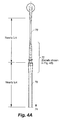
- In accordance with the present invention, various stack and regenerator units, with optional pistons, are placed in a cascading relationship. FIGS. 4A and 4B illustrate one example that has been investigated in detail using the computer implemented DeltaE simulation code. A
cascade 72 provides, in series, (1st) astack unit 82 functioning as an engine, (2nd) afirst regenerator unit 84 functioning as an engine, and (3rd) asecond regenerator unit 86 functioning as an engine, which finally delivers acoustic power to a load 74 (e.g., a refrigerator or a linear alternator) below. -
Stack unit 82 includesstack 88 with inputambient heat exchanger 92 on the top side andhot heat exchanger 94 on the bottom side.Regenerator unit 84 is separated fromstack unit 82 bythermal buffer tube 104, as explained below, and includesregenerator 96 withambient heat exchanger 98 on the top side andhot heat exchanger 102 on the bottom side. Asecond regenerator unit 86 is separated fromregenerator unit 84 bythermal buffer tube 114.Regenerator 106 hasambient heat exchanger 108 on the top side andhot heat exchanger 112 on the bottom side.Hot heat exchanger 112 is connected to an output resonator throughthermal buffer tube 116. As used herein, “top” and “bottom” sides are well defined, becausethermal buffer tubes - The space inside of
pressure housing 118 and outside ofstack unit 82,regenerator units thermal buffer tubes Bellows 120 accommodates axial thermal expansion ofstack unit 82,regenerator units thermal buffer tubes pressure housing 118. - The qualitative descriptions presented herein are intended to teach the invention to those skilled in the art. The DeltaE computer code that is used to simulate embodiments of the present invention has been experimentally validated, has been broadly distributed, and is in widespread use among those skilled in the art. The User Guide describes its algorithms in detail and is available at www.lanl.gov/thermoacoustics, incorporated herein by reference. Hence, DeltaE simulations were used to provide a quantitatively accurate depiction of the detailed acoustic and thermodynamic processes of the present invention, e.g., such as depicted as an exemplary embodiment in FIGS. 4A and 4B. Those skilled in the art will recognize that DeltaE simulations can readily be used to explore other embodiments of the invention, such as cascaded refrigerators and the like.
- The present invention involves the location of the regenerator unit(s) and/or stack unit(s) in the acoustic wave. It is known to those skilled in the art that both stacks and regenerators operate best at locations of high specific acoustic impedance, where specific acoustic impedance is the ratio of the amplitude of the oscillating pressure to the amplitude of the oscillating velocity. As used herein, a “high specific acoustic impedance” is greater than the product of gas density and gas sound speed, usually by roughly an order of magnitude (e.g., typically 30 for regenerator units and 5 for stack units). See, e.g., “Thermoacoustics: a unifying perspective for some engines and refrigerators,” G. W. Swift, advanced textbook to be published by the Acoustical Society of America in 2002; draft available before the publication date at www.lanl.gov/thermoacoustics/, incorporated herein by reference. It is taught in U.S. Pat. No. 4,355,517 to Ceperley, U.S. Pat. No. 4,398,398 to Wheatley et al., and U.S. Pat. No. 4,489,553 to Wheatley et al. that this condition requires putting the stacks and regenerators in a wave with substantial standing-wave character and near the oscillating pressure maximum of that wave. For example, to set this value equal to 5 (typical for a stack unit) in a standing wave described by
- p(x,t)P o cos(2πx/λ)cos(2πft),
- u(x,t)=(P o /ρa)sin(2πx/λ)sin(2πft)
- requires that tan(2πx/λ)=1/5, i.e., x/λ=0.03. P o is the amplitude of the pressure oscillation at the location of its maximum, p(x,t) and u(x,t) are the oscillating pressure and velocity as functions of position x and time t (with x=0 at the location of the maximum in oscillating pressure), ρ is the gas density, a is the gas sound speed, f is the frequency of the oscillations, and λ=a/f is the wavelength.
- The locations of the
stack unit 82 and the tworegenerator units wave tubes cascade 72, so that the threeunits segments containing cascade 72,upper wave tube 78, andlower wave tube 76 are similar to two nearly quarter-wave resonators of different cross sectional areas, with velocity maxima at the upper end ofupper wave tube 78 and at the lower end oflower wave tube 76. - The term “nearly quarter wave” is used because Hofler [T. J. Hofler, “Thermoacoustic refrigerator design and performance,” 1986, Physics department thesis, University of California, San Diego] taught that a desired acoustic impedance could be maintained at a location of a stack (or regenerator), while less acoustic power is dissipated in the attached resonator, by providing resonator geometry with slightly reduced cross sectional area and slightly reduced length in the region of high velocity. These reductions are typically between 25% and 50%. The reduced surface area resulting from these geometry reductions leads to less boundary-layer acoustic power dissipation. Reducing the dimensions too much, however, raises velocities enough to raise dissipation again. Hofler, supra, teaches the optimum dimensions giving minimum power dissipation. For clarity, these shape details are not shown in FIGS. 5A-F.
- The present invention provides for the efficient creation, amplification, or, in the case of refrigerators, use of acoustic power. Regenerator units are more efficient than stack units, so it is desirable to use regenerator units as much as possible. However, regenerator engine units require injection of acoustic power at the ambient end, which leads to the use of pistons, displacers and toroidal acoustic networks in prior art engines. Similarly, regenerator refrigerator units require removal of acoustic power at the cold end, which leads to the use of displacers, toroidal acoustic networks, or dissipative orifices in prior art refrigerators.
- In the present invention, cascaded regenerator engine units can be used to provide great amplification of a small amount of acoustic power that is created by a small stack unit or a small oscillating piston. By using multiple cascaded regenerator engine units, it is possible to use a small stack engine unit or a small, driven oscillating piston or even a loudspeaker to create the initial acoustic power (or, in the case of cascaded refrigerators, to consume the final acoustic power), so the comparatively low efficiency of the stack unit or the comparatively high cost of the oscillating piston or the comparatively low efficiency of the loudspeaker have a small impact on the entire system's efficiency or cost.
- For example, the simulation of the system shown in FIGS. 4A and 4B showed that
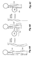
stack unit 82 creates 14 kW of acoustic power, and delivers 12 kW of it to first regenerator unit 84 (the other 2 kW flowing up to feed the unavoidable dissipation in the upper portions of the resonator),first regenerator unit 84 amplifies that 12 kW to 26 kW, which it delivers tosecond regenerator unit 86, andsecond regenerator unit 86 amplifies that 26 kW to 58 kW. Thus, of the 58 kW available to a load, only 12 kW was generated by the relativelyinefficient stack unit 82; the remaining 46 kW was generated in the moreefficient regenerator units - Other resonator geometries, including those shown in FIGS. 5A-F, can accomplish the same acoustics as the resonator shown in FIG. 4A. FIGS. 5A and 5B show resonators with lengths equal to one acoustic wavelength, with a uniform cross sectional area or a cross sectional area having a transition at the midpoint, respectively. The ends of these resonators are closed, so
regions region 128 could contain a stack engine unit,region 132 could contain a second stack engine unit and one or two engine regenerator units, andregion 134 could contain an additional regenerator engine unit. The bottom end of the resonator could then be the location of a noncompliant linear alternator to convert the acoustic power created by all the engine units into electricity. The area change shown in FIG. 5B can accommodate units of differing cross sectional areas, which is useful when the units handle differing amounts of power. - FIG. 5C is a depiction of a resonator of the type used in FIG. 4A, in the simplified scheme of FIGS. 5A-F in which the shape details of the resonator are not shown.
Region 136 of high specific acoustic impedance is the location suitable for a cascade, such ascascade 72 of FIG. 4. - FIG. 5D shows that an
electroacoustic power transducer 140 can be located just belowregion 138 of high specific acoustic impedance. Iftransducer 140 is a motor, thenregion 138 can contain a cascade of refrigerator units. Iftransducer 140 is an alternator, thenregion 138 can contain a cascade of engine units. - FIGS. 5E and 5F show two additional, related ways to create more than one region of high specific acoustic impedance in a resonator. The resonator in FIG. 5F is an extended version of the resonator in FIG. 5C, and can be extended indefinitely: Each extension by λ/2 adds a new region of high specific acoustic impedance wherein stack units or regenerator units can be located.
Region 148 in FIG. 5F corresponds toregion 136 in FIG. 5C, andregion 150 in FIG. 5F is a new region of high specific acoustic impedance, separated fromregion 148 by approximately λ/2. FIG. 5E shows a shorter way to create more than one region of high specific acoustic impedance. The central zone of any of the resonator portions marked “λ/2” in FIGS. 5A, 5B, and 5F is essentially inertial in character, so an inertially massive free piston (usually not attached to a power transducer) can provide the same acoustic-impedance transformation if shorter height is more important than avoidance of moving parts.Free piston 144 in FIG. 5E replaces the central zone of the resonator portion marked “λ/2” in FIG. 5F. - An embodiment that cascades a stack unit and three regenerator units within a single region of high specific acoustic impedance as shown in any of FIGS. 5A-F has been simulated. At some larger number of units, however, there will be insufficient space within that region of the wave to accommodate all the units, and additional cascaded units, if desired, would have to be located in other regions of high specific acoustic impedance, in resonators having more than one such region, such as those shown in FIGS. 5A, 5B, 5E and 5F.
- Alternatively, side branches can be used to create axially extended regions of high specific acoustic impedance, where a side branch is generally orthogonal to the axis of a resonator. FIG. 6A shows the resonator of FIG. 5F, along with a graph showing the in-phase part of the oscillating pressure and the out-of-phase part of the oscillating volume flow rate (i.e., the integral, over the cross sectional area, of the velocity) as functions of axial position along the resonator. The two
regions - FIG. 6B shows the use of an
acoustic side branch 154 that creates an axiallyextended region 158 of high specific acoustic impedance, whose axial length is the sum of the axial lengths ofregions bulb 155 at the end ofacoustic side branch 154 is very large, then the cross sectional area A and length L of the side-branch tube must satisfy PJ/2UJ=(ρa/A)tan(2πL/λ). From among the many sets A, L of solutions to this equation, one can be chosen to minimize size or dissipation or some other figure of merit. The side branch can also be implemented with abulb 165 andfree piston 164, as shown in FIG. 6C. - Examination of the graphs in FIG. 6B shows that a region of high specific acoustic impedance of even greater axial length can be created by periodically attaching additional side branches to such a resonator.
- Two oppositely directed side branches, at the same axial location, can also be used to create an extended region of high specific acoustic impedance, if vibration cancellation in the horizontal direction is important.
- Further, the present invention acts to prevent heat leak from the hot end of one unit to the ambient end of the adjacent unit in the case of engines and the prevention of heat leak from the ambient end of one unit to the cold end of the adjacent unit in the case of refrigerators. Both forms of heat leak reduce system efficiency. At each such location between units, it is necessary to provide a thermal buffer tube for thermal isolation. Thermal buffer tubes have been described in the context of thermoacoustic-Stirling hybrid engines and refrigerators in U.S. Pat. No. 6,032,464 to Swift et al., and they are very well known as “pulse tubes” in the context of orifice pulse tube refrigerators. Ideally, a slug of the gas in the axially central portion of a thermal buffer tube experiences adiabatic pressure oscillations and temperature-stratified velocity/motion oscillations, so that this slug of gas behaves like an axially compressible, but otherwise intact, thermally insulating oscillating piston. Axial internal motion of any portion of the gas in this slug relative to other gas in this slug should be avoided, because such motion convects heat from one end of the slug to the other. Such undesirable axial internal motion can be caused by gravity-driven convection, by inadequate flow straightening at the ends of the thermal buffer tube causing jets to extend into the central portion of the thermal buffer tube, or by Rayleigh streaming. In all of the figures herein, “up” and “down” have been chosen for stability of the thermal buffer tubes against gravity-driven convection.
- Clearly, if the length of the thermal buffer tube is shorter than the peak-to-peak displacement of the gas therein, no slug of gas as described in the previous paragraph can exist, because no slug of gas remains within the thermal buffer tube throughout a full cycle of the oscillations. Hence, the thermal buffer tube is preferably longer than the peak-to-peak displacement of the gas therein. Good design practice among those skilled in the arts of orifice pulse tube refrigerators and thermoacoustic-Stirling hybrid engines typically calls for thermal buffer tubes to have a length equal to or greater than approximately 3 peak-to-peak gas displacement amplitudes.
- Hence, the present invention includes thermal buffer tubes between all units when the heat exchangers separated by such thermal buffer tubes have unequal temperatures.
- Thermal buffer tubes sometimes require a taper to suppress Rayleigh streaming as described in U.S. Pat. No. 5,953,920 to Olson et al. In some situations in the present invention, the thermal buffer tube is so short and broad, and the required taper is so extreme, that the assumptions on which taper calculation of the '920 patent was based break down, and, in particular, flow separation at the wall might occur. This may be solved by subdividing the area of the tapered thermal buffer tube with a number of louvers so that a number of thermal buffer tubes in parallel are effectively formed, each having a taper for which the '920 patent teaching is applicable Such a thermal buffer tube is not needed where a stack unit functioning as an engine is in the latter portion of one region of high specific acoustic impedance and a regenerator unit is in the closest neighboring region of high specific acoustic impedance. In this case, a thermal buffer tube between the ambient heat exchanger of the stack unit and the ambient heat exchanger of the regenerator unit is unnecessary, because it spans no temperature difference.
- It should be noted that the exact location of the pressure maximum in the system can depend on gas temperatures in the high-velocity portions of the resonator. This condition can be exploited for fine tuning of acoustic conditions at a stack unit or regenerator unit (Anthony J. Lesperance, “Hardware modifications and instrumentation of the thermoacoustically driven thermoacoustic refrigerator,” Master's thesis, September 1997, Engineering Acoustics Department, US Naval Postgraduate School, Monterey Calif. 93943) by controlling the temperature of one high-velocity portion of the resonator with an electrical heater. The temperature changes needed to effect this control are small, typically 30° C. The same control can be obtained by other heating means or by cooling means, such as cooling water or waste heat from a burner; or by variable-geometry resonators.
- The above discussion is directed to cascaded engines, but the same principles apply to refrigerators. Two or three regenerator refrigerator units can be cascaded if the refrigerator units do not span too large a temperature difference. However, DeltaE simulation shows that cascading two cryogenic regenerator refrigerator units within a single region of high specific acoustic impedance leads to rather low efficiency for one or both of the refrigerators, because each such cryogenic unit demands a substantial fraction of a wavelength in the wave and the efficiency of cryogenic regenerator units is fairly sensitive to the specific acoustic impedance. A stack refrigerator unit following a regenerator refrigerator unit also looks useful. As for the engine cascades, thermal buffer tubes between refrigerator units are required.
- FIGS. 7A and 7B schematically depict two examples of how the cascade ideas disclosed here can be integrated into complete thermoacoustic systems.
- FIG. 7A shows a thermoacoustic refrigerator system driven by a
linear motor 170. The resonator arrangement, especiallyside branch 173 and the λ/4 portion, create an axiallyextended region 178 of high specific acoustic impedance. From bottom to top, inregion 178 are firstregenerator refrigerator unit 172, athermal buffer tube 175, the junction toside branch 173, a shortinertial section 171 of wave tube to raise the pressure amplitude slightly, secondregenerator refrigerator unit 174, anotherthermal buffer tube 177, and stackrefrigerator unit 176. Anotherthermal buffer tube 179 abovestack refrigerator unit 176 can be outside ofregion 178. Acoustic power flows upward through, and is consumed by, all threerefrigerator units refrigerator units - FIG. 7B shows a combined thermoacoustic engine and refrigerator system, such as might be used to cryogenically liquefy nitrogen by using combustion of natural gas as a source of power. The resonator arrangement includes three
side branches stack engine unit 182, athermal buffer tube 189, firstregenerator engine unit 184, anotherthermal buffer tube 191, secondregenerator engine unit 185, anotherthermal buffer tube 193, a junction toside branch 183, a shortinertial section 195 of wave tube to raise the pressure amplitude slightly, thirdregenerator engine unit 186, anotherthermal buffer tube 197, a junction toside branch 181, firstregenerator refrigerator unit 192, anotherthermal buffer tube 199, a junction toside branch 187, another shortinertial section 201 of wave tube to raise the pressure amplitude slightly, secondregenerator refrigerator unit 194, anotherthermal buffer tube 208, and stackrefrigerator unit 196. Anotherthermal buffer tube 205 abovestack refrigerator unit 196 can be outside of the region of high specific acoustic impedance. - Acoustic power is created by
stack engine unit 182, flows downward through and is amplified by the threeregenerator engine units regenerator refrigerator units stack refrigerator unit 196. All three refrigerator units have their cold heat exchangers on top and their ambient heat exchangers on the bottom, and all four engine units have their ambient heat exchangers on top and their hot heat exchangers on the bottom; hence, all thermal buffer tubes are gravitationally stable. - The above discussion is generally directed to regenerator units and stack units in which the oscillating fluid flows in all portions of each such unit are essentially parallel, such as through the short dimension of a regenerator unit shaped like a hockey puck. However, the same principles apply to stacks and regenerators shaped like a cylindrical annulus, with the oscillating flow in the radial direction; and to other geometries.
- The foregoing description of the invention has been presented for purposes of illustration and description and is not intended to be exhaustive or to limit the invention to the precise form disclosed, and obviously many modifications and variations are possible in light of the above teaching. The embodiments were chosen and described in order to best explain the principles of the invention and its practical application to thereby enable others skilled in the art to best utilize the invention in various embodiments and with various modifications as are suited to the particular use contemplated. It is intended that the scope of the invention be defined by the claims appended hereto.
Claims (18)
Priority Applications (3)
| Application Number | Priority Date | Filing Date | Title |
|---|---|---|---|
| US10/125,268 US6658862B2 (en) | 2002-04-18 | 2002-04-18 | Cascaded thermoacoustic devices |
| AU2003226037A AU2003226037A1 (en) | 2002-04-18 | 2003-04-09 | Cascaded thermoacoustic devices |
| PCT/US2003/010919 WO2003089848A1 (en) | 2002-04-18 | 2003-04-09 | Cascaded thermoacoustic devices |
Applications Claiming Priority (1)
| Application Number | Priority Date | Filing Date | Title |
|---|---|---|---|
| US10/125,268 US6658862B2 (en) | 2002-04-18 | 2002-04-18 | Cascaded thermoacoustic devices |
Publications (2)
| Publication Number | Publication Date |
|---|---|
| US20030196441A1 true US20030196441A1 (en) | 2003-10-23 |
| US6658862B2 US6658862B2 (en) | 2003-12-09 |
Family
ID=29214766
Family Applications (1)
| Application Number | Title | Priority Date | Filing Date |
|---|---|---|---|
| US10/125,268 Expired - Fee Related US6658862B2 (en) | 2002-04-18 | 2002-04-18 | Cascaded thermoacoustic devices |
Country Status (3)
| Country | Link |
|---|---|
| US (1) | US6658862B2 (en) |
| AU (1) | AU2003226037A1 (en) |
| WO (1) | WO2003089848A1 (en) |
Cited By (12)
| Publication number | Priority date | Publication date | Assignee | Title |
|---|---|---|---|---|
| US20070044484A1 (en) * | 2005-08-23 | 2007-03-01 | Sunpower, Inc. | Pulse tube cooler having 1/4 wavelength resonator tube instead of reservoir |
| US20100037627A1 (en) * | 2006-09-07 | 2010-02-18 | David Proctor | Capture and removal of gases from other gases in a gas stream |
| US20110252811A1 (en) * | 2010-04-20 | 2011-10-20 | King Abdul Aziz City For Science And Technology | Travelling wave thermoacoustic piezoelectric system for generating electrical energy from heat energy |
| US20110252812A1 (en) * | 2010-04-20 | 2011-10-20 | King Abdul Aziz City For Science And Technology | Travelling wave thermoacoustic piezoelectric refrigerator |
| DE102010050244A1 (en) | 2010-10-30 | 2012-05-03 | Technische Universität Bergakademie Freiberg | Chisel direct drive for tools based on a heat engine |
| FR3044714A1 (en) * | 2015-12-08 | 2017-06-09 | Airbus Group Sas | HYBRID POWER OR THRUST GENERATOR AND VEHICLE COMPRISING SUCH A GENERATOR |
| IT201700004695A1 (en) * | 2017-01-17 | 2018-07-17 | Armido Cremaschi | Energy generation and storage system for the home (NEST-house) |
| WO2020050780A1 (en) * | 2018-09-04 | 2020-03-12 | Gorenje Gospodinjski Aparati, D.D. | Method for heat transfer in the embedded structure of a heat regenerator and the design thereof |
| US11041458B2 (en) * | 2017-06-15 | 2021-06-22 | Etalim Inc. | Thermoacoustic transducer apparatus including a working volume and reservoir volume in fluid communication through a conduit |
| CN113310247A (en) * | 2020-06-02 | 2021-08-27 | 中国科学院理化技术研究所 | Multi-stage thermoacoustic refrigerator for room temp. region |
| CN113494432A (en) * | 2020-04-08 | 2021-10-12 | 中国科学院理化技术研究所 | Nuclear heat thermoacoustic power generation system |
| US20220177146A1 (en) * | 2020-12-03 | 2022-06-09 | Airbus Sas | Electric propulsion system of an aircraft |
Families Citing this family (21)
| Publication number | Priority date | Publication date | Assignee | Title |
|---|---|---|---|---|
| KR100454271B1 (en) * | 2002-08-16 | 2004-10-26 | 엘지전선 주식회사 | Heat-Driving Acoustic Orifice Pulse Tube Cryocooling Device |
| US7062921B2 (en) * | 2002-12-30 | 2006-06-20 | Industrial Technology Research Institute | Multi-stage thermoacoustic device |
| FR2869945B1 (en) * | 2004-05-04 | 2006-08-04 | Univ Paris Curie | POWER TRANSMISSION UNIT FOR THERMOACOUSTIC SYSTEMS |
| CN1328507C (en) * | 2004-09-10 | 2007-07-25 | 中国科学院理化技术研究所 | Coaxial thermoacoustic driving power generation system |
| CN100344920C (en) * | 2004-11-24 | 2007-10-24 | 中国科学院理化技术研究所 | Supercharging device for refrigerating machine driven by thermoacoustic engine |
| US7628022B2 (en) * | 2005-10-31 | 2009-12-08 | Clever Fellows Innovation Consortium, Inc. | Acoustic cooling device with coldhead and resonant driver separated |
| US8443599B2 (en) * | 2006-09-02 | 2013-05-21 | The Doshisha | Thermoacoustic apparatus |
| CN100593678C (en) * | 2006-12-31 | 2010-03-10 | 中国科学院理化技术研究所 | Tandem type thermoacoustic system |
| US7908856B2 (en) * | 2007-10-24 | 2011-03-22 | Los Alamos National Security, Llc | In-line stirling energy system |
| US8468838B2 (en) * | 2008-04-01 | 2013-06-25 | Los Alamos National Security, Llc | Thermoacoustic refrigerators and engines comprising cascading stirling thermodynamic units |
| US8181460B2 (en) * | 2009-02-20 | 2012-05-22 | e Nova, Inc. | Thermoacoustic driven compressor |
| WO2010107308A1 (en) | 2009-02-25 | 2010-09-23 | Cornelis Maria De Blok | Multistage traveling wave thermoacoustic engine with phase distributed power extraction |
| US8205459B2 (en) * | 2009-07-31 | 2012-06-26 | Palo Alto Research Center Incorporated | Thermo-electro-acoustic refrigerator and method of using same |
| US8227928B2 (en) * | 2009-07-31 | 2012-07-24 | Palo Alto Research Center Incorporated | Thermo-electro-acoustic engine and method of using same |
| US8401216B2 (en) * | 2009-10-27 | 2013-03-19 | Saab Sensis Corporation | Acoustic traveling wave tube system and method for forming and propagating acoustic waves |
| US8375729B2 (en) | 2010-04-30 | 2013-02-19 | Palo Alto Research Center Incorporated | Optimization of a thermoacoustic apparatus based on operating conditions and selected user input |
| US8584471B2 (en) | 2010-04-30 | 2013-11-19 | Palo Alto Research | Thermoacoustic apparatus with series-connected stages |
| US8950193B2 (en) | 2011-01-24 | 2015-02-10 | The United States of America, as represented by the Secretary of Commerce, The National Institute of Standards and Technology | Secondary pulse tubes and regenerators for coupling to room temperature phase shifters in multistage pulse tube cryocoolers |
| US9163581B2 (en) * | 2012-02-23 | 2015-10-20 | The United States Of America As Represented By The Administrator Of National Aeronautics And Space Administration | Alpha-stream convertor |
| JP6495098B2 (en) * | 2015-05-21 | 2019-04-03 | 中央精機株式会社 | Thermoacoustic power generation system |
| US12128869B2 (en) | 2017-10-27 | 2024-10-29 | Quantum Industrial Development Corporation | External combustion engine series hybrid electric drivetrain |
Family Cites Families (9)
| Publication number | Priority date | Publication date | Assignee | Title |
|---|---|---|---|---|
| US4355517A (en) | 1980-11-04 | 1982-10-26 | Ceperley Peter H | Resonant travelling wave heat engine |
| US4489553A (en) | 1981-08-14 | 1984-12-25 | The United States Of America As Represented By The United States Department Of Energy | Intrinsically irreversible heat engine |
| US4722201A (en) * | 1986-02-13 | 1988-02-02 | The United States Of America As Represented By The United States Department Of Energy | Acoustic cooling engine |
| US5167124A (en) * | 1988-10-11 | 1992-12-01 | Sonic Compressor Systems, Inc. | Compression-evaporation cooling system having standing wave compressor |
| DE69110868T2 (en) * | 1991-04-30 | 1996-02-22 | Ibm | Cryogenic generation process and expansion machine. |
| US5515684A (en) * | 1994-09-27 | 1996-05-14 | Macrosonix Corporation | Resonant macrosonic synthesis |
| US6109041A (en) * | 1996-11-05 | 2000-08-29 | Mitchell; Matthew P. | Pulse tube refrigerator |
| US5901556A (en) * | 1997-11-26 | 1999-05-11 | The United States Of America As Represented By The Secretary Of The Navy | High-efficiency heat-driven acoustic cooling engine with no moving parts |
| JP4147697B2 (en) | 1999-09-20 | 2008-09-10 | アイシン精機株式会社 | Pulse tube refrigerator |
-
2002
- 2002-04-18 US US10/125,268 patent/US6658862B2/en not_active Expired - Fee Related
-
2003
- 2003-04-09 WO PCT/US2003/010919 patent/WO2003089848A1/en not_active Ceased
- 2003-04-09 AU AU2003226037A patent/AU2003226037A1/en not_active Abandoned
Cited By (19)
| Publication number | Priority date | Publication date | Assignee | Title |
|---|---|---|---|---|
| US7434409B2 (en) | 2005-08-23 | 2008-10-14 | Sunpower, Inc. | Pulse tube cooler having ¼ wavelength resonator tube instead of reservoir |
| US20070044484A1 (en) * | 2005-08-23 | 2007-03-01 | Sunpower, Inc. | Pulse tube cooler having 1/4 wavelength resonator tube instead of reservoir |
| US20100037627A1 (en) * | 2006-09-07 | 2010-02-18 | David Proctor | Capture and removal of gases from other gases in a gas stream |
| US8371130B2 (en) * | 2010-04-20 | 2013-02-12 | King Abdul Aziz City for Science and Technology (KACST) | Travelling wave thermoacoustic piezoelectric system for generating electrical energy from heat energy |
| US20110252811A1 (en) * | 2010-04-20 | 2011-10-20 | King Abdul Aziz City For Science And Technology | Travelling wave thermoacoustic piezoelectric system for generating electrical energy from heat energy |
| US20110252812A1 (en) * | 2010-04-20 | 2011-10-20 | King Abdul Aziz City For Science And Technology | Travelling wave thermoacoustic piezoelectric refrigerator |
| DE102010050244B4 (en) * | 2010-10-30 | 2013-10-17 | Technische Universität Bergakademie Freiberg | Chisel direct drive for tools based on a heat engine |
| WO2012055392A2 (en) | 2010-10-30 | 2012-05-03 | Technische Universität Bergakademie Freiberg | Direct drill bit drive for tools on the basis of a heat engine |
| DE102010050244A1 (en) | 2010-10-30 | 2012-05-03 | Technische Universität Bergakademie Freiberg | Chisel direct drive for tools based on a heat engine |
| RU2601633C2 (en) * | 2010-10-30 | 2016-11-10 | Маркус ШВАРЦ | Direct drive of drilling bit for tools on basis of thermal engine |
| FR3044714A1 (en) * | 2015-12-08 | 2017-06-09 | Airbus Group Sas | HYBRID POWER OR THRUST GENERATOR AND VEHICLE COMPRISING SUCH A GENERATOR |
| WO2017098144A1 (en) * | 2015-12-08 | 2017-06-15 | Airbus Group Sas | Hybrid power or thrust generator and vehicle including such a generator |
| IT201700004695A1 (en) * | 2017-01-17 | 2018-07-17 | Armido Cremaschi | Energy generation and storage system for the home (NEST-house) |
| US11041458B2 (en) * | 2017-06-15 | 2021-06-22 | Etalim Inc. | Thermoacoustic transducer apparatus including a working volume and reservoir volume in fluid communication through a conduit |
| WO2020050780A1 (en) * | 2018-09-04 | 2020-03-12 | Gorenje Gospodinjski Aparati, D.D. | Method for heat transfer in the embedded structure of a heat regenerator and the design thereof |
| CN113494432A (en) * | 2020-04-08 | 2021-10-12 | 中国科学院理化技术研究所 | Nuclear heat thermoacoustic power generation system |
| CN113310247A (en) * | 2020-06-02 | 2021-08-27 | 中国科学院理化技术研究所 | Multi-stage thermoacoustic refrigerator for room temp. region |
| US20220177146A1 (en) * | 2020-12-03 | 2022-06-09 | Airbus Sas | Electric propulsion system of an aircraft |
| US12129039B2 (en) * | 2020-12-03 | 2024-10-29 | Airbus Sas | Electric propulsion system of an aircraft |
Also Published As
| Publication number | Publication date |
|---|---|
| AU2003226037A1 (en) | 2003-11-03 |
| US6658862B2 (en) | 2003-12-09 |
| WO2003089848A1 (en) | 2003-10-30 |
Similar Documents
| Publication | Publication Date | Title |
|---|---|---|
| US6658862B2 (en) | Cascaded thermoacoustic devices | |
| US6560970B1 (en) | Oscillating side-branch enhancements of thermoacoustic heat exchangers | |
| Bi et al. | Development of a 5 kW traveling-wave thermoacoustic electric generator | |
| Garrett | Resource letter: TA-1: Thermoacoustic engines and refrigerators | |
| US6032464A (en) | Traveling-wave device with mass flux suppression | |
| US9777951B2 (en) | Thermoacoustic engine | |
| Swift | Thermoacoustic engines | |
| US5996345A (en) | Heat driven acoustic power source coupled to an electric generator | |
| US6910332B2 (en) | Thermoacoustic engine-generator | |
| Chi et al. | Study of a gas-liquid-coupled heat-driven room-temperature thermoacoustic refrigerator with different working gases | |
| Xu et al. | A cascade-looped thermoacoustic driven cryocooler with different-diameter resonance tubes. Part I: Theoretical analysis of thermodynamic performance and characteristics | |
| CN105485956B (en) | Cascade regenerative refrigerator | |
| WO2004015336A1 (en) | Circulating heat exchangers for oscillating wave engines and refrigerators | |
| CN100371657C (en) | Pulse tube refrigerator | |
| Backhaus et al. | New varieties of thermoacoustic engines | |
| US6510689B2 (en) | Method and device for transmitting mechanical energy between a stirling machine and a generator or an electric motor | |
| CN109974324A (en) | A kind of thermoacoustic cyclic system can be used as power generation, refrigeration or heat pump | |
| US8640467B2 (en) | Acoustic power transmitting unit for thermoacoustic systems | |
| JP2007530911A (en) | Cryogenic cooler system with frequency-converting mechanical resonator | |
| CN1086801C (en) | Thermoacoustic refrigerator | |
| Wakeland et al. | Thermoacoustics with idealized heat exchangers and no stack | |
| Tiwatane et al. | Thermoacoustic effect: the power of conversion of sound energy & heat energy | |
| Swift | Thermoacoustics | |
| Jaworski et al. | 4.2 Thermoacoustic engines | |
| Arafa et al. | Developments and recent patents on Thermoacoustic devices |
Legal Events
| Date | Code | Title | Description |
|---|---|---|---|
| AS | Assignment |
Owner name: CALIFORNIA, THE REGENTS OF THE UNIVERSITY OF, NEW Free format text: ASSIGNMENT OF ASSIGNORS INTEREST;ASSIGNORS:SWIFT, GREGORY W.;BACKHAUS, SCOTT N.;GARDNER, DAVID L.;REEL/FRAME:012971/0635 Effective date: 20020507 Owner name: REGENTS OF THE UNIVERSITY OF CALIFORNIA, THE, NEW Free format text: ASSIGNMENT OF ASSIGNORS INTEREST;ASSIGNORS:SWIFT, GREGORY W.;BACKHAUS, SCOTT N.;GARDNER, DAVID L.;REEL/FRAME:012971/0635 Effective date: 20020507 |
|
| AS | Assignment |
Owner name: ENERGY U.S. DEPARTMENT OF, DISTRICT OF COLUMBIA Free format text: CONFIRMATORY LICENSE;ASSIGNOR:CALIFORNIA UNIVERSITY OF;REEL/FRAME:013419/0241 Effective date: 20020603 |
|
| AS | Assignment |
Owner name: LOS ALAMOS NATIONAL SECURITY, LLC, NEW MEXICO Free format text: ASSIGNMENT OF ASSIGNORS INTEREST;ASSIGNOR:THE REGENTS OF THE UNIVERSITY OF CALIFORNIA;REEL/FRAME:017897/0873 Effective date: 20060410 |
|
| FEPP | Fee payment procedure |
Free format text: PAT HOLDER NO LONGER CLAIMS SMALL ENTITY STATUS, ENTITY STATUS SET TO UNDISCOUNTED (ORIGINAL EVENT CODE: STOL); ENTITY STATUS OF PATENT OWNER: LARGE ENTITY |
|
| FPAY | Fee payment |
Year of fee payment: 4 |
|
| FPAY | Fee payment |
Year of fee payment: 8 |
|
| REMI | Maintenance fee reminder mailed | ||
| LAPS | Lapse for failure to pay maintenance fees | ||
| STCH | Information on status: patent discontinuation |
Free format text: PATENT EXPIRED DUE TO NONPAYMENT OF MAINTENANCE FEES UNDER 37 CFR 1.362 |
|
| STCH | Information on status: patent discontinuation |
Free format text: PATENT EXPIRED DUE TO NONPAYMENT OF MAINTENANCE FEES UNDER 37 CFR 1.362 |
|
| FP | Lapsed due to failure to pay maintenance fee |
Effective date: 20151209 |