US20030112901A1 - Method and apparatus for determining the log-likelihood ratio with precoding - Google Patents
Method and apparatus for determining the log-likelihood ratio with precoding Download PDFInfo
- Publication number
- US20030112901A1 US20030112901A1 US10/305,587 US30558702A US2003112901A1 US 20030112901 A1 US20030112901 A1 US 20030112901A1 US 30558702 A US30558702 A US 30558702A US 2003112901 A1 US2003112901 A1 US 2003112901A1
- Authority
- US
- United States
- Prior art keywords
- signal
- set forth
- bit
- value
- constellation
- Prior art date
- Legal status (The legal status is an assumption and is not a legal conclusion. Google has not performed a legal analysis and makes no representation as to the accuracy of the status listed.)
- Granted
Links
- 238000000034 method Methods 0.000 title claims abstract description 52
- 230000006854 communication Effects 0.000 claims abstract description 31
- 238000004891 communication Methods 0.000 claims abstract description 31
- 230000005540 biological transmission Effects 0.000 description 25
- 238000013507 mapping Methods 0.000 description 16
- 230000006870 function Effects 0.000 description 13
- 125000004122 cyclic group Chemical group 0.000 description 9
- 238000010586 diagram Methods 0.000 description 9
- 238000005562 fading Methods 0.000 description 7
- 238000012545 processing Methods 0.000 description 5
- 230000015556 catabolic process Effects 0.000 description 4
- 238000006731 degradation reaction Methods 0.000 description 4
- 230000000694 effects Effects 0.000 description 4
- 230000004044 response Effects 0.000 description 4
- 230000003595 spectral effect Effects 0.000 description 4
- 238000012546 transfer Methods 0.000 description 4
- 238000013461 design Methods 0.000 description 3
- 238000004088 simulation Methods 0.000 description 3
- 230000000295 complement effect Effects 0.000 description 2
- 238000012986 modification Methods 0.000 description 2
- 230000004048 modification Effects 0.000 description 2
- 239000002245 particle Substances 0.000 description 2
- 230000008569 process Effects 0.000 description 2
- 238000007493 shaping process Methods 0.000 description 2
- 239000000654 additive Substances 0.000 description 1
- 230000000996 additive effect Effects 0.000 description 1
- 238000013459 approach Methods 0.000 description 1
- 230000007175 bidirectional communication Effects 0.000 description 1
- 239000000969 carrier Substances 0.000 description 1
- 239000000470 constituent Substances 0.000 description 1
- 230000000593 degrading effect Effects 0.000 description 1
- 230000002939 deleterious effect Effects 0.000 description 1
- 239000006185 dispersion Substances 0.000 description 1
- 238000005516 engineering process Methods 0.000 description 1
- 230000002708 enhancing effect Effects 0.000 description 1
- 230000003287 optical effect Effects 0.000 description 1
Images


Classifications
-
- H—ELECTRICITY
- H04—ELECTRIC COMMUNICATION TECHNIQUE
- H04L—TRANSMISSION OF DIGITAL INFORMATION, e.g. TELEGRAPHIC COMMUNICATION
- H04L27/00—Modulated-carrier systems
- H04L27/26—Systems using multi-frequency codes
-
- H—ELECTRICITY
- H04—ELECTRIC COMMUNICATION TECHNIQUE
- H04L—TRANSMISSION OF DIGITAL INFORMATION, e.g. TELEGRAPHIC COMMUNICATION
- H04L1/00—Arrangements for detecting or preventing errors in the information received
- H04L1/004—Arrangements for detecting or preventing errors in the information received by using forward error control
- H04L1/0056—Systems characterized by the type of code used
- H04L1/0064—Concatenated codes
- H04L1/0066—Parallel concatenated codes
-
- H—ELECTRICITY
- H04—ELECTRIC COMMUNICATION TECHNIQUE
- H04L—TRANSMISSION OF DIGITAL INFORMATION, e.g. TELEGRAPHIC COMMUNICATION
- H04L1/00—Arrangements for detecting or preventing errors in the information received
- H04L1/004—Arrangements for detecting or preventing errors in the information received by using forward error control
- H04L1/0045—Arrangements at the receiver end
- H04L1/0054—Maximum-likelihood or sequential decoding, e.g. Viterbi, Fano, ZJ algorithms
-
- H—ELECTRICITY
- H04—ELECTRIC COMMUNICATION TECHNIQUE
- H04L—TRANSMISSION OF DIGITAL INFORMATION, e.g. TELEGRAPHIC COMMUNICATION
- H04L25/00—Baseband systems
- H04L25/02—Details ; arrangements for supplying electrical power along data transmission lines
- H04L25/03—Shaping networks in transmitter or receiver, e.g. adaptive shaping networks
- H04L25/03006—Arrangements for removing intersymbol interference
- H04L25/03343—Arrangements at the transmitter end
-
- H—ELECTRICITY
- H04—ELECTRIC COMMUNICATION TECHNIQUE
- H04L—TRANSMISSION OF DIGITAL INFORMATION, e.g. TELEGRAPHIC COMMUNICATION
- H04L25/00—Baseband systems
- H04L25/02—Details ; arrangements for supplying electrical power along data transmission lines
- H04L25/06—Dc level restoring means; Bias distortion correction ; Decision circuits providing symbol by symbol detection
- H04L25/067—Dc level restoring means; Bias distortion correction ; Decision circuits providing symbol by symbol detection providing soft decisions, i.e. decisions together with an estimate of reliability
-
- H—ELECTRICITY
- H04—ELECTRIC COMMUNICATION TECHNIQUE
- H04L—TRANSMISSION OF DIGITAL INFORMATION, e.g. TELEGRAPHIC COMMUNICATION
- H04L25/00—Baseband systems
- H04L25/38—Synchronous or start-stop systems, e.g. for Baudot code
- H04L25/40—Transmitting circuits; Receiving circuits
- H04L25/49—Transmitting circuits; Receiving circuits using code conversion at the transmitter; using predistortion; using insertion of idle bits for obtaining a desired frequency spectrum; using three or more amplitude levels ; Baseband coding techniques specific to data transmission systems
- H04L25/497—Transmitting circuits; Receiving circuits using code conversion at the transmitter; using predistortion; using insertion of idle bits for obtaining a desired frequency spectrum; using three or more amplitude levels ; Baseband coding techniques specific to data transmission systems by correlative coding, e.g. partial response coding or echo modulation coding transmitters and receivers for partial response systems
- H04L25/4975—Correlative coding using Tomlinson precoding, Harashima precoding, Trellis precoding or GPRS
-
- H—ELECTRICITY
- H04—ELECTRIC COMMUNICATION TECHNIQUE
- H04L—TRANSMISSION OF DIGITAL INFORMATION, e.g. TELEGRAPHIC COMMUNICATION
- H04L27/00—Modulated-carrier systems
- H04L27/02—Amplitude-modulated carrier systems, e.g. using on-off keying; Single sideband or vestigial sideband modulation
- H04L27/06—Demodulator circuits; Receiver circuits
-
- H—ELECTRICITY
- H04—ELECTRIC COMMUNICATION TECHNIQUE
- H04L—TRANSMISSION OF DIGITAL INFORMATION, e.g. TELEGRAPHIC COMMUNICATION
- H04L27/00—Modulated-carrier systems
- H04L27/10—Frequency-modulated carrier systems, i.e. using frequency-shift keying
- H04L27/14—Demodulator circuits; Receiver circuits
-
- H—ELECTRICITY
- H04—ELECTRIC COMMUNICATION TECHNIQUE
- H04L—TRANSMISSION OF DIGITAL INFORMATION, e.g. TELEGRAPHIC COMMUNICATION
- H04L25/00—Baseband systems
- H04L25/02—Details ; arrangements for supplying electrical power along data transmission lines
- H04L25/03—Shaping networks in transmitter or receiver, e.g. adaptive shaping networks
- H04L25/03006—Arrangements for removing intersymbol interference
- H04L2025/0335—Arrangements for removing intersymbol interference characterised by the type of transmission
- H04L2025/03375—Passband transmission
- H04L2025/03414—Multicarrier
-
- H—ELECTRICITY
- H04—ELECTRIC COMMUNICATION TECHNIQUE
- H04L—TRANSMISSION OF DIGITAL INFORMATION, e.g. TELEGRAPHIC COMMUNICATION
- H04L27/00—Modulated-carrier systems
- H04L27/26—Systems using multi-frequency codes
- H04L27/2601—Multicarrier modulation systems
- H04L27/2647—Arrangements specific to the receiver only
Definitions
- the invention generally relates to wireless communications. More specifically, the invention relates to an apparatus and method for determining the log-likelihood ratio for turbo codes and branch metric for convolutional codes when precoding is used.
- Wireless communication systems are widely deployed to provide various types of communication such as voice, packet data, and so on. These systems may be based on code division multiple access (CDMA), time division multiple access (TDMA), orthogonal frequency division multiplexing (OFDM) or some other multiple access techniques.
- CDMA code division multiple access
- TDMA time division multiple access
- OFDM orthogonal frequency division multiplexing
- OFDM orthogonal frequency division multiple access
- a disadvantage of OFDM systems is the overhead associated with the guard tones in frequency domain and cyclic prefix in time domain. Inefficiency also results from the data transmission block resolution problem.
- the minimum block size for transmission is the number of bits per OFDM symbol. This number can be large if the number of carriers is large and the high order modulation alphabet is used.
- the frame length in general, is not an integral multiple of number of bits per OFDM symbol, bits are wasted in padding. The wastage due to padding can be significant, especially for small frame length.
- OFDM orthogonal frequency division multiplexing
- OFDM used with good channel codes alleviates some of the problems described above.
- Channel coding in conjunction with a channel interleaver also eliminates the need for bit loading in OFDM system.
- channel coding does not solve the efficiency problem of OFDM. If the OFDM parameters are not properly selected, then the data transmission efficiency can be appreciably low.
- Band limited single carrier system with high order quadrature amplitude modulation (QAM) modulation is widely used scheme for data transmission at high rate with high spectral efficiency for wire line as well as line-of-sight wireless system. It does not suffer from the above-mentioned disadvantages of OFDM.
- the channel equalization for single carrier system in severe multi-path fading channel is a difficult task.
- Linear equalizer fails to provide satisfactory performance. It has been found through simulation that even if a lower rate channel code is used with a single carrier system, in order to make the total overhead or the spectral efficiency same for a single carrier and a OFDM system, the single carrier performance with linear equalizer and the ideal equalizer taps is only slightly better than the OFDM.
- DFE decision feedback equalizer
- ISI inter-symbol interference
- a number of methods have been proposed to reduce the affect of the error propagation in the DFE.
- One method suggests assigning a reliability measure to each equalized soft symbol.
- the symbol estimate to be fed back to the DFE is based on this reliability. For example, if the equalized symbol has a high reliability, the hard decision is fed back; otherwise the equalized symbol without the hard decision is fed back.
- aspects of the invention describe an apparatus and method for recovering data transmitted in a wireless communication system that reduces the affect of error propagation.
- a plurality of modulation symbols from a plurality of coded bits is received.
- An apparatus and method for recovering data transmitted in a wireless communication system is claimed.
- a plurality of signal points, the signal point comprising a plurality of modulation symbols from a plurality of coded bits is received.
- a first subset of signal points for which a bit is equal to a first value and a second subset of signal points for which the bit is equal to a second value is determined.
- the first and second subsets are signal points from an expanded signal constellation.
- the expanded set constellation is expanded by adding 2Mi to each point in the original constellation, where M is the number of signal points in an underlying one-dimensional signal constellation and i is an integer.
- the probability that the bit is equal to the first value or the second value is determined as a function of the received signal point.
- a soft decision symbol may then be determined, based on the probability that the bit is equal to the first value or the second value.
- the soft decision symbols may be represented as log likelihood ratios.
- the channel coding which utilizes the soft decision to compute the bit LLR for turbo codes (or bit branch metric for soft decision Viterbi decoding of convolutional codes), then folding the received constellation (by a modulo function) before computing the bit LLR or branch metric results in a severe performance degradation of the decoder.
- the LLR determination is done using an expanded signal constellation, thus significantly improving operation of the decoder.
- FIG. 1 illustrates a simplified block diagram of a communication system capable of implementing various aspects and embodiments of the invention
- FIGS. 2A and 2B are block diagrams of two transmitter units that code and modulate data with (1) a single coding and modulation scheme and (2) separate coding and modulation schemes on a per-antenna basis, respectively;
- FIG. 3 illustrates a block diagram of a communication system incorporating a precoder
- FIG. 4 illustrates a block diagram of a communication system employing turbo coding and precoding
- FIG. 5 illustrates an example of a received modulo signal constellation and an expanded signal constellation
- FIG. 6 illustrates a flowchart of the steps undertaken to determine the soft decision symbol.
- Precoding is a well-known technique to eliminate the effect of error propagation and approach the performance of an ideal decision feedback analyzer (DFE).
- DFE decision feedback analyzer
- the idea of precoding is as follows.
- An ideal DFE requires a perfect estimate of the channel as well as the past symbols.
- a receiver can obtain almost perfect estimate of the channel but it cannot have perfect estimates of the past symbols.
- a transmitter has a perfect knowledge of the past symbols.
- pre-equalization of the channel may occur.
- WLAN wireless local area network
- WAN applications where the access point and user are virtually stationary or slowly moving, the wireless channel may be considered reciprocal. Then both the access point and the user have the estimates of the channel, since the channel is the same in both directions.
- the precoding is still a viable option.
- the channel estimates can be measured and sent back to the transmitter from the receiver during the initial session prior to the data transmission.
- Direct pre-equalization suffers from the problem of possible increase in transmitted power as well as possible increase in peak-to-average power.
- this problem is very elegantly solved by the Tomlinson-Harashima (TH) precoding.
- FIG. 1 is a simplified block diagram of a communication system 100 capable of implementing various aspects and embodiments of the invention.
- communication system 100 is a CDMA system that conforms to cdma2000, W-CDMA, IS-856, and/or some other CDMA standards.
- TX transmit
- TMTR transmitter
- the analog signals are then provided to a transmitter (TMTR) 116 that (quadrature) modulates, filters, amplifies, and upconverts the signal(s) to generate a modulated signal.
- the modulated signal is then transmitted via one or more antennas 118 (only one is shown in FIG. 1) to one or more receiver units.
- the transmitted signal is received by one or more antennas 152 (again, only one is shown) and provided to a receiver (RCVR) 154 .
- the received signal(s) are amplified, filtered, downconverted, (quadrature) demodulated, and digitized to generate samples.
- the samples are then processed and decoded by a receive (RX) data processor 156 to recover the transmitted data.
- the processing and decoding at receiver unit 150 are performed in a manner complementary to the processing and coding performed at transmitter unit 110 .
- the recovered data is then provided to a data sink 158 .
- FIG. 2A is a block diagram of a transmitter unit 200 a , which is an embodiment of the transmitter portion of transmitter system 110 in FIG. 1.
- Transmitter unit 200 a includes (1) a TX data processor 114 a that receives and codes traffic data in accordance with a specific coding scheme to provide coded data and (2) a modulator 116 a that modulates the coded data in accordance with a specific modulation scheme to provide modulated data.
- TX data processor 114 a and modulator 116 a are thus one embodiment of TX data processor 114 and modulator 116 , respectively, in FIG. 1.
- TX data processor 114 a includes an encoder 212 , a channel interleaver 214 , and a demultiplexer (Demux) 216 .
- Encoder 212 receives and codes the traffic data (i.e., the information bits) in accordance with the selected coding scheme to provide coded bits.
- the coding increases the reliability of the data transmission.
- the selected coding scheme may include any combination of cyclic redundancy check (CRC) coding, convolutional coding, Turbo coding, block coding, and so on.
- Channel interleaver 214 then interleaves the coded bits based on a particular interleaving scheme and provides interleaved coded bits.
- the interleaving provides time diversity for the coded bits, permits the data to be transmitted based on an average signal-to-noise-and-interference ratio (SNR) for the frequency and/or spatial subchannels used for the data transmission, combats fading, and further removes correlation between coded bits used to form each modulation symbol.
- SNR signal-to-noise-and-interference ratio
- the interleaving may further provide frequency diversity if the coded bits are transmitted over multiple frequency subchannels. The coding and channel interleaving are described in further detail below.
- Demultiplexer 216 then demultiplexes the interleaved and coded data into N T coded data streams for the N T transmit antennas to be used for the data transmission.
- the N T coded data streams are then provided to modulator 116 a.
- modulator 116 a includes N T OFDM modulators, with each OFDM modulator assigned to process a respective coded data stream for one transmit antenna.
- Each OFDM modulator includes a symbol mapping element 222 , an inverse fast Fourier transformer (IFFT) 224 , and a cyclic prefix generator 226 .
- IFFT inverse fast Fourier transformer
- cyclic prefix generator 226 In this embodiment, all N T symbol mapping elements 222 a through 222 t implement the same modulation scheme.
- symbol mapping element 222 maps the received coded bits to modulation symbols for the (up to) N F frequency subchannels to be used for data transmission on the transmit antenna associated with the OFDM modulator.
- the particular modulation scheme to be implemented by symbol mapping element 222 is determined by the modulation control provided by controller 130 .
- Symbol mapping element 222 then provides a vector of (up to) N F modulation symbols for each transmission symbol period, with the number of modulation symbols in each vector corresponding to the number of frequency subchannels to be used for data transmission for that transmission symbol period.
- Gray mapping may be preferably used for the symbol mapping since it may provide better performance in terms of bit error rate (BER).
- BER bit error rate
- the neighboring points in the signal constellation (in both the horizontal and vertical directions) differ by only one out of the q bit positions. Gray mapping reduces the number of bit errors for more likely error events, which correspond to a received modulation symbol being mapped to a location near the correct location, in which case only one coded bit would be received in error.
- IFFT 224 then converts each modulation symbol vector into its time-domain representation (which is referred to as an OFDM symbol) using the inverse fast Fourier transform.
- IFFT 224 may be designed to perform the inverse transform on any number of frequency subchannels (e.g., 8, 16, 32, . . . , N F , . . . ).
- cyclic prefix generator 226 repeats a portion of the OFDM symbol to form a corresponding transmission symbol.
- the cyclic prefix ensures that the transmission symbol retains its orthogonal properties in the presence of multipath delay spread, thereby improving performance against deleterious path effects such as channel dispersion caused by frequency selective fading.
- the transmission symbols from cyclic prefix generator 226 are then provided to an associated transmitter 122 and processed to generate a modulated signal, which is then transmitted from the associated antenna 124 .
- FIG. 2B is a block diagram of a transmitter unit 200 b , which is another embodiment of the transmitter portion of transmitter system 110 in FIG. 1.
- a particular coding scheme is used for each of the N T transmit antennas and a particular modulation scheme is used for all N F frequency subchannels of each transmit antenna (i.e., separate coding and modulation on a per-antenna basis).
- the specific coding and modulation schemes to be used for each transmit antenna may be selected based on the expected channel conditions (e.g., by the receiver system and sent back to the transmitter system).
- Transmitter unit 200 b includes (1) a TX data processor 114 b that receives and codes traffic data in accordance with separate coding schemes to provide coded data and (2) a modulator 116 b that modulates the coded data in accordance with separate modulation schemes to provide modulated data.
- TX data processor 114 b and modulator 116 b are another embodiment of TX data processor 114 and modulator 116 , respectively, in FIG. 1.
- TX data processor 114 b includes a demultiplexer 210 , N T encoders 212 a through 212 t , and N T channel interleavers 214 a through 214 t (i.e., one set of encoder and channel interleaver for each transmit antenna).
- Demultiplexer 210 demultiplexes the traffic data (i.e., the information bits) into N T data streams for the N T transmit antennas to be used for the data transmission. Each data stream is then provided to a respective encoder 212 .
- Each encoder 212 receives and codes a respective data stream based on the specific coding scheme selected for the corresponding transmit antenna to provide coded bits.
- the coded bits from each encoder 212 are then provided to a respective channel interleaver 214 , which interleaves the coded bits based on a particular interleaving scheme to provide diversity.
- Channel interleavers 214 a through 214 t then provide to modulator 116 b N T interleaved and coded data streams for the N T transmit antennas.
- modulator 116 b includes N T OFDM modulators, with each OFDM modulator including symbol mapping element 222 , IFFT 224 , and cyclic prefix generator 226 .
- the N T symbol mapping elements 222 a through 222 t may implement different modulation schemes.
- the subsequent processing by IFFT 224 and cyclic prefix generator 226 is as described above.
- the transmitter unit may also be implemented and are within the scope of the invention.
- the coding and modulation may be separately performed for each subset of transmit antennas, each transmission channel, or each group of transmission channels.
- the implementation of encoders 212 , channel interleavers 214 , symbol mapping elements 222 , IFFTs 224 , and cyclic prefix generators 226 is known in the art and not described in detail herein.
- Various types of encoder may be used to code data prior to transmission.
- the encoder may implement any one of the following (1) a serial concatenated convolutional code (SCCC), (2) a parallel concatenated convolutional code (PCCC), (3) a simple convolutional code, (4) a concatenated code comprised of a block code and a convolutional code, and so on.
- SCCC serial concatenated convolutional code
- PCCC parallel concatenated convolutional code
- simple convolutional code (4) a concatenated code comprised of a block code and a convolutional code, and so on.
- Concatenated convolutional codes are also referred to as Turbo codes.
- the signal processing described above supports transmissions of voice, video, packet data, messaging, and other types of communication in one direction.
- a bi-directional communication system supports two-way data transmission, and operates in a similar manner.
- FIG. 3 illustrates a block diagram 300 of a communication system incorporating a precoder.
- a k denotes the complex modulation symbol 304 from QAM signal constellation, where k is the time index.
- Square QAM signal constellation is considered, which may be regarded as the Cartesian product of two PAM constellations having M points, namely ( ⁇ (M ⁇ 1), ⁇ (M ⁇ 3), . . . , (M ⁇ 3), (M ⁇ 1)).
- the complex modulation symbol 304 is input into precoder 308 .
- the precoder function 312 is defined as
- X k a k ⁇ [X k-1 h ⁇ 1 +X k-2 h ⁇ 2 + . . . +X k-L h ⁇ L ]mod 2 M (1)
- X k a k +2 M ( l k +jm k ) ⁇ [ X k-1 h ⁇ 1 +X k-2 h ⁇ 2 + . . . +X k-L h ⁇ L ] (2)
- l k and m k are integers such that the real and imaginary portions of X k are between +/ ⁇ M; that is, ⁇ M ⁇ Re[X k ], Im[X k ] ⁇ M.
- the precoder function is a function of the current symbol (a k ) minus the product of prior precoder outputs (X k-1 , and so on) and the prior channel impulse response (h ⁇ 1 , and so on).
- H(z) in FIG. 3 denotes the combined transfer function 316 of the transmit filter, multi-path channel, receive filter and feedforward filter of the equalizer, as illustrated by block 450 in FIG. 4 (see FIG. 4 infra.). Assuming that the combined channel impulse response is limited to L+1 symbols, H(z) is represented by
- N k denotes the complex added white Guassian noise (AWGN) 324 having a power spectral density of N 0 /2.
- AWGN complex added white Guassian noise
- the MOD 2M function 332 represents limiting the transmitted signal energy closer to the energy of the unexpected constellation and W k ( 336 ) denotes the decision statistics.
- the performance of the precoder is slightly worse than that of an ideal DFE equalizer for at least the following reasons: the signal after precoding is no longer discrete, but uniformly distributed between [ ⁇ M, M] resulting in slightly higher transmitted energy for the same minimum distance between two signal points. This is known as precoding loss and it is given by M 2 - 1 M 2 .
- FIG. 4 A block diagram of a communication system 400 employing turbo coding and precoding is illustrated in FIG. 4.
- a binary data block 404 to be transmitted is encoded with a turbo encoder 408 , which generates a sequence of code bits 412 .
- the turbo code may be parallel or serial concatenated codes. Also, puncturing may be used to generate any code rate.
- the sequence of code bits 412 is fed to a mapper 416 , where they are grouped together (2log 2 M) and mapped to a point in M 2 -QAM signal constellation. In an embodiment, Gray codes are used.
- the mapper 416 output is a sequence of complex-value modulation symbols 420 .
- the complex-value symbol sequence 420 is input into a precoder 424 . The function of the precoder is discussed in the description with respect to FIG. 3.
- the precoder output is also complex value 428 .
- the complex value signal 428 comprises real and imaginary parts uniformly distributed between ⁇ M and +M, where M represents the number of signal point in the constituent pulse amplitude modulation (PAM) constellation.
- the precoder output 428 is then input to a pulse shaping transmit filter 432 .
- a receive filter 436 is the complementary shaping filter at the receiver. Both the transmit filter 432 and the receive filter 436 may be square-root Nyquist filters, such that the combined response is Nyquist.
- the transmit channel 440 for WLAN may be modeled as independent multi-path Reyleigh fading channel followed by additive white Gaussian noise (AWGN) 444 .
- a feed-forward filter 448 is the feed-forward part of the channel equalizer and may be fractionally spaced.
- the receive filter 436 combined with feed-forward filter may be considered to be equivalent to combined channel matched filter and the noise-whitening filter.
- the coefficients of the feed-forward filter and the precoder can be computed using the Minimum Mean Square Error (MMSE) criterion.
- MMSE Minimum Mean Square Error
- Z n denotes the feedforward filter's output 452 , which is fed into the LLR metric computer 456 (n is the time index).
- LLR metric computer 456 may be a microprocessor, software, microcode running on a microprocessor, embodied in an application specific integrated circuit (ASIC), or in some other form.
- the output 460 of LLR computer 456 gives a probability that a particular bit is a particular value, and is input into a concatenated convolutional coder 464 , such as a turbo coder, thereby producing decoded data 468 .
- a n is the corresponding transmitted QAM symbol and N n ′ is the complex AWGN noise sample.
- Z n is the received soft decision for the transmitted symbol a n .
- LLR computer block 456 computes 2log 2 M bit LLRs for each received soft QAM symbol. Due to the product symmetry of square QAM constellation and the Gray code mapping, the LLR of a particular code bit is a function of either A n (the real portion) or B n (the imaginary portion) and the corresponding one-dimensional PAM signal points. In other words, for the purpose of computing LLRs, the received QAM signal can be considered to be consisting of two independent PAM signals.
- the received soft decisions A n and B n belong to expanded PAM signal constellation.
- the LLR is determined by determining the probability that An was received given that s was transmitted.
- the LLR computation may incorporate affects of noise factors ⁇ 2 .
- Performing a Mod 2M operation on A n and B n folds the received signal point into the basic constellation, which is appropriate if the hard decision is to be performed on A n and B n .
- the channel coding which utilizes the soft decision to compute the bit LLR for turbo codes (or bit branch metric for soft decision Viterbi decoding of convolutional codes)
- folding the received constellation before computing the bit LLR or branch metric results in a severe performance degradation of the decoder. This is exemplified in FIG. 5.
- FIG. 5 illustrates a received modulo signal constellation and an expanded signal constellation.
- Box 504 represents the modulo (unexpanded) signal constellation comprising of points ⁇ 3, ⁇ 1, 1, and 3, which correspond to gray codes (for bits b 0 and b 1 ), 11, 10, 00 and 01, respectively. If a point 508 is received as illustrated (just outside of “4”) and a modulo 2M operation were performed, point 508 translates to point 512 (just inside of ⁇ 4). In an unexpanded constellation, the probability of point 512 being either a 0 or 1 is evaluated. The probability of bit b 0 being “1” is extremely high, since the only near by value for bit b 0 is “1” (say approximately a 95% probability).
- the probability of point 508 being either a 0 or 1 is evaluated. Since point 508 is slightly closer to “11” than “01”, the probability of bit b 0 being “1” is much lower (say approximately a 55% probability). Thus, use of an expanded signal constellation before computing the LLR, and not using the modulo 2M operation, yields a significantly more accurate probability determination of the given bit.
- the modification of eliminating the modulo operation and computing the bit LLR on the expanded signal constellation is used for computing the bit LLR or branch metric when a precoder is present.
- the set S k 0 and S k 0 is expanded by adding 2Mi to each point in the original set where i is an integer.
- the LLR is then determined using the expanded set.
- the cardinality of the expanded signal set S k 0 and S k 0 is four times larger than the original set. This increases the complexity of LLR computation significantly. However, this can be minimized if only those points that are within ⁇ M of the received point for LLR or metric computation are considered.
- FIG. 6 illustrates a flowchart 600 of the method by which the LLR is determined.
- a plurality of demodulated signal points is received 604 .
- the demodulated signal points comprise a plurality of coded bits and noise.
- a first subset of signal points and a second subset of signal points are determined 608 .
- the probability of a given bit being received, given that a particular soft decision was received is determined 612 .
- the received soft decision belongs to the expanded signal constellation.
- the LLR is determined 616 as the logarithm of the ratio of the summation of the probabilities that the bit received is a “1” or a “0”.
- Antenna diversity such as in a multiple input multiple output (MIMO) system, is a powerful scheme to improve the performance of data transmission over a fading channel.
- MIMO multiple input multiple output
- DSP digital signal processor
- ASIC application specific integrated circuit
- FPGA field programmable gate array
- a general purpose processor may be a microprocessor, but in the alternative, the processor may be any conventional processor, controller, microcontroller, or state machine.
- a processor may also be implemented as a combination of computing devices, e.g., a combination of a DSP and a microprocessor, a plurality of microprocessors, one or more microprocessors in conjunction with a DSP core, or any other such configuration.
- a software module may reside in RAM memory, flash memory, ROM memory, EPROM memory, EEPROM memory, registers, hard disk, a removable disk, a CD-ROM, or any other form of storage medium known in the art.
- the processor and an associated storage medium may reside in an application specific integrated circuit (ASIC).
- the ASIC may reside in a subscriber unit, or in some form of wireless infrastructure.
- the processor and the storage medium may reside as discrete components in a user terminal.
Abstract
Description
- This application claims priority from U.S. Provisional Patent Application Serial No. 60/334,363, entitled, “Turbo Coding with Precoding for Multi-Path Fading Channel,” filed Nov. 29, 2001, which is incorporated by reference herein.
- I. Field
- The invention generally relates to wireless communications. More specifically, the invention relates to an apparatus and method for determining the log-likelihood ratio for turbo codes and branch metric for convolutional codes when precoding is used.
- II. Background
- Wireless communication systems are widely deployed to provide various types of communication such as voice, packet data, and so on. These systems may be based on code division multiple access (CDMA), time division multiple access (TDMA), orthogonal frequency division multiplexing (OFDM) or some other multiple access techniques.
- Over a severe multi-path fading wireless channel, data transmission at a high rate with high spectral efficiency is a challenging task. Currently, OFDM is considered an effective modulation technique for such a channel. OFDM has been adopted for several wireless LAN standards. OFDM is also often considered for broadband wireless access (BWA) systems. Though OFDM modulation is indeed very effective in dealing with severe multi-path fading channel, it suffers from several disadvantages.
- A disadvantage of OFDM systems is the overhead associated with the guard tones in frequency domain and cyclic prefix in time domain. Inefficiency also results from the data transmission block resolution problem. The minimum block size for transmission is the number of bits per OFDM symbol. This number can be large if the number of carriers is large and the high order modulation alphabet is used. For a burst data transmission system, since the frame length, in general, is not an integral multiple of number of bits per OFDM symbol, bits are wasted in padding. The wastage due to padding can be significant, especially for small frame length.
- Another notable disadvantage of OFDM is its greater susceptibility to non-linearity and phase noise. The amplitude of the OFDM modulated signal is gaussian distributed. The high peak-to-average power ratio of an OFDM signal makes it susceptible to nonlinear or clipping distortion, as the signal peaks may occasionally thrust into the saturation region of the power amplifier. The result is bit error rate (BER) degradation and adjacent channel interference. Thus, larger output power back-off is needed to reduce the OFDM signal degradation.
- OFDM used with good channel codes alleviates some of the problems described above. Channel coding in conjunction with a channel interleaver also eliminates the need for bit loading in OFDM system. However, channel coding does not solve the efficiency problem of OFDM. If the OFDM parameters are not properly selected, then the data transmission efficiency can be appreciably low.
- Band limited single carrier system with high order quadrature amplitude modulation (QAM) modulation is widely used scheme for data transmission at high rate with high spectral efficiency for wire line as well as line-of-sight wireless system. It does not suffer from the above-mentioned disadvantages of OFDM. However, the channel equalization for single carrier system in severe multi-path fading channel is a difficult task. Linear equalizer fails to provide satisfactory performance. It has been found through simulation that even if a lower rate channel code is used with a single carrier system, in order to make the total overhead or the spectral efficiency same for a single carrier and a OFDM system, the single carrier performance with linear equalizer and the ideal equalizer taps is only slightly better than the OFDM.
- Use of a decision feedback equalizer (DFE) is well known to be very effective equalization technique for a channel with severe inter-symbol interference (ISI) problems. DFE requires the estimates of past symbols without delay to subtract the ISI contributed by them to the current symbol. If the past symbol estimates are error free, then the ISI contributed by them can be completely subtracted without enhancing noise. This explains the superior performance of ideal DFE, which assumes that error free estimates of the past symbols are available at the receiver. If an incorrect decision is made on the past symbol, then the error propagation can occur. It has been found through simulation that for a severe multi-path channel, the effect of error propagation is so bad that the performance of a DFE is worse than that of a linear equalizer.
- A number of methods have been proposed to reduce the affect of the error propagation in the DFE. One method suggests assigning a reliability measure to each equalized soft symbol. The symbol estimate to be fed back to the DFE is based on this reliability. For example, if the equalized symbol has a high reliability, the hard decision is fed back; otherwise the equalized symbol without the hard decision is fed back.
- Another method suggests iterating between equalization and channel decoder in a turbo-like manner and has been named “turbo-equalization” in the literature. The main idea is if the channel decoder generates better estimates of the code bits at its output than what it received from the equalizer at its input, this can be fed back to DFE. Consequently during the next iteration of DFE less error propagation will occur within DFE and so on. The first method has almost negligible incremental implementation complexity whereas the second method has substantial increase in complexity and delay. Unfortunately, these methods have been found to be only marginally effective in combating the effect of error propagation.
- There is therefore a need in the art for techniques to reduce the affect of the error propagation.
- Aspects of the invention describe an apparatus and method for recovering data transmitted in a wireless communication system that reduces the affect of error propagation. A plurality of modulation symbols from a plurality of coded bits is received. An apparatus and method for recovering data transmitted in a wireless communication system is claimed. A plurality of signal points, the signal point comprising a plurality of modulation symbols from a plurality of coded bits, is received. A first subset of signal points for which a bit is equal to a first value and a second subset of signal points for which the bit is equal to a second value is determined. The first and second subsets are signal points from an expanded signal constellation. In an embodiment, the expanded set constellation is expanded by adding 2Mi to each point in the original constellation, where M is the number of signal points in an underlying one-dimensional signal constellation and i is an integer.
- The probability that the bit is equal to the first value or the second value is determined as a function of the received signal point. A soft decision symbol may then be determined, based on the probability that the bit is equal to the first value or the second value. The soft decision symbols may be represented as log likelihood ratios.
- When the channel coding is present, which utilizes the soft decision to compute the bit LLR for turbo codes (or bit branch metric for soft decision Viterbi decoding of convolutional codes), then folding the received constellation (by a modulo function) before computing the bit LLR or branch metric results in a severe performance degradation of the decoder. As such, the LLR determination is done using an expanded signal constellation, thus significantly improving operation of the decoder.
- Various aspects and embodiments of the invention are described in further detail below. The invention further provides techniques, methods, receivers, transmitters, systems, and other apparatuses and elements that implement various aspects, embodiments, and features of the invention, as described in further detail below.
- The features, nature, and advantages of the present invention will become more apparent from the detailed description set forth below when taken in conjunction with the drawings in which like reference characters identify correspondingly throughout and wherein:
- FIG. 1 illustrates a simplified block diagram of a communication system capable of implementing various aspects and embodiments of the invention;
- FIGS. 2A and 2B are block diagrams of two transmitter units that code and modulate data with (1) a single coding and modulation scheme and (2) separate coding and modulation schemes on a per-antenna basis, respectively;
- FIG. 3 illustrates a block diagram of a communication system incorporating a precoder;
- FIG. 4 illustrates a block diagram of a communication system employing turbo coding and precoding;
- FIG. 5 illustrates an example of a received modulo signal constellation and an expanded signal constellation; and
- FIG. 6 illustrates a flowchart of the steps undertaken to determine the soft decision symbol.
- Precoding is a well-known technique to eliminate the effect of error propagation and approach the performance of an ideal decision feedback analyzer (DFE). The idea of precoding is as follows. An ideal DFE requires a perfect estimate of the channel as well as the past symbols. A receiver can obtain almost perfect estimate of the channel but it cannot have perfect estimates of the past symbols. On the other hand, a transmitter has a perfect knowledge of the past symbols. Thus, if the transmitter can obtain the estimate of the channel, then pre-equalization of the channel may occur. For wireless local area network (WLAN) or WAN applications where the access point and user are virtually stationary or slowly moving, the wireless channel may be considered reciprocal. Then both the access point and the user have the estimates of the channel, since the channel is the same in both directions. If the assumption of reciprocity is not valid for some reason, the precoding is still a viable option. The channel estimates can be measured and sent back to the transmitter from the receiver during the initial session prior to the data transmission. Direct pre-equalization suffers from the problem of possible increase in transmitted power as well as possible increase in peak-to-average power. However, this problem is very elegantly solved by the Tomlinson-Harashima (TH) precoding.
- FIG. 1 is a simplified block diagram of a
communication system 100 capable of implementing various aspects and embodiments of the invention. In an embodiment,communication system 100 is a CDMA system that conforms to cdma2000, W-CDMA, IS-856, and/or some other CDMA standards. At atransmitter unit 110, data is sent, typically in blocks, from adata source 112 to a transmit (TX)data processor 114 that formats, codes, and processes the data to generate one or more analog signals. The analog signals are then provided to a transmitter (TMTR) 116 that (quadrature) modulates, filters, amplifies, and upconverts the signal(s) to generate a modulated signal. The modulated signal is then transmitted via one or more antennas 118 (only one is shown in FIG. 1) to one or more receiver units. - At a receiver unit 150, the transmitted signal is received by one or more antennas 152 (again, only one is shown) and provided to a receiver (RCVR) 154. Within receiver 154, the received signal(s) are amplified, filtered, downconverted, (quadrature) demodulated, and digitized to generate samples. The samples are then processed and decoded by a receive (RX) data processor 156 to recover the transmitted data. The processing and decoding at receiver unit 150 are performed in a manner complementary to the processing and coding performed at
transmitter unit 110. The recovered data is then provided to a data sink 158. - FIG. 2A is a block diagram of a
transmitter unit 200 a, which is an embodiment of the transmitter portion oftransmitter system 110 in FIG. 1. In this embodiment, a single coding scheme is used for all NT transmit antennas and a single modulation scheme is used for all NF frequency subchannels of all transmit antennas.Transmitter unit 200 a includes (1) aTX data processor 114 a that receives and codes traffic data in accordance with a specific coding scheme to provide coded data and (2) amodulator 116 a that modulates the coded data in accordance with a specific modulation scheme to provide modulated data.TX data processor 114 a andmodulator 116 a are thus one embodiment ofTX data processor 114 andmodulator 116, respectively, in FIG. 1. - In the specific embodiment shown in FIG. 2A,
TX data processor 114 a includes anencoder 212, achannel interleaver 214, and a demultiplexer (Demux) 216.Encoder 212 receives and codes the traffic data (i.e., the information bits) in accordance with the selected coding scheme to provide coded bits. The coding increases the reliability of the data transmission. The selected coding scheme may include any combination of cyclic redundancy check (CRC) coding, convolutional coding, Turbo coding, block coding, and so on. Several designs forencoder 212 are described below. -
Channel interleaver 214 then interleaves the coded bits based on a particular interleaving scheme and provides interleaved coded bits. The interleaving provides time diversity for the coded bits, permits the data to be transmitted based on an average signal-to-noise-and-interference ratio (SNR) for the frequency and/or spatial subchannels used for the data transmission, combats fading, and further removes correlation between coded bits used to form each modulation symbol. The interleaving may further provide frequency diversity if the coded bits are transmitted over multiple frequency subchannels. The coding and channel interleaving are described in further detail below. -
Demultiplexer 216 then demultiplexes the interleaved and coded data into NT coded data streams for the NT transmit antennas to be used for the data transmission. The NT coded data streams are then provided to modulator 116 a. - In the specific embodiment shown in FIG. 2A, modulator 116 a includes NT OFDM modulators, with each OFDM modulator assigned to process a respective coded data stream for one transmit antenna. Each OFDM modulator includes a symbol mapping element 222, an inverse fast Fourier transformer (IFFT) 224, and a cyclic prefix generator 226. In this embodiment, all NT
symbol mapping elements 222 a through 222 t implement the same modulation scheme. - Within each OFDM modulator, symbol mapping element 222 maps the received coded bits to modulation symbols for the (up to) NF frequency subchannels to be used for data transmission on the transmit antenna associated with the OFDM modulator. The particular modulation scheme to be implemented by symbol mapping element 222 is determined by the modulation control provided by
controller 130. For OFDM, the modulation may be achieved by grouping sets of q coded bits to form non-binary symbols and mapping each non-binary symbol to a specific point in a signal constellation corresponding to the selected modulation scheme (e.g., QPSK, M-PSK, M-QAM, or some other scheme). Each mapped signal point corresponds to an M-ary modulation symbol, where M=2q. Symbol mapping element 222 then provides a vector of (up to) NF modulation symbols for each transmission symbol period, with the number of modulation symbols in each vector corresponding to the number of frequency subchannels to be used for data transmission for that transmission symbol period. - If conventional non-iterative symbol de-mapping and decoding are performed at the receiver system, then Gray mapping may be preferably used for the symbol mapping since it may provide better performance in terms of bit error rate (BER). With Gray mapping, the neighboring points in the signal constellation (in both the horizontal and vertical directions) differ by only one out of the q bit positions. Gray mapping reduces the number of bit errors for more likely error events, which correspond to a received modulation symbol being mapped to a location near the correct location, in which case only one coded bit would be received in error.
- IFFT 224 then converts each modulation symbol vector into its time-domain representation (which is referred to as an OFDM symbol) using the inverse fast Fourier transform. IFFT 224 may be designed to perform the inverse transform on any number of frequency subchannels (e.g., 8, 16, 32, . . . , NF, . . . ). In an embodiment, for each OFDM symbol, cyclic prefix generator 226 repeats a portion of the OFDM symbol to form a corresponding transmission symbol. The cyclic prefix ensures that the transmission symbol retains its orthogonal properties in the presence of multipath delay spread, thereby improving performance against deleterious path effects such as channel dispersion caused by frequency selective fading. The transmission symbols from cyclic prefix generator 226 are then provided to an associated transmitter 122 and processed to generate a modulated signal, which is then transmitted from the associated antenna 124.
- FIG. 2B is a block diagram of a
transmitter unit 200 b, which is another embodiment of the transmitter portion oftransmitter system 110 in FIG. 1. In this embodiment, a particular coding scheme is used for each of the NT transmit antennas and a particular modulation scheme is used for all NF frequency subchannels of each transmit antenna (i.e., separate coding and modulation on a per-antenna basis). The specific coding and modulation schemes to be used for each transmit antenna may be selected based on the expected channel conditions (e.g., by the receiver system and sent back to the transmitter system). -
Transmitter unit 200 b includes (1) aTX data processor 114 b that receives and codes traffic data in accordance with separate coding schemes to provide coded data and (2) amodulator 116 b that modulates the coded data in accordance with separate modulation schemes to provide modulated data.TX data processor 114 b andmodulator 116 b are another embodiment ofTX data processor 114 andmodulator 116, respectively, in FIG. 1. - In the specific embodiment shown in FIG. 2B,
TX data processor 114 b includes ademultiplexer 210, NT encoders 212 a through 212 t, and NT channel interleavers 214 a through 214 t (i.e., one set of encoder and channel interleaver for each transmit antenna).Demultiplexer 210 demultiplexes the traffic data (i.e., the information bits) into NT data streams for the NT transmit antennas to be used for the data transmission. Each data stream is then provided to arespective encoder 212. - Each
encoder 212 receives and codes a respective data stream based on the specific coding scheme selected for the corresponding transmit antenna to provide coded bits. The coded bits from eachencoder 212 are then provided to arespective channel interleaver 214, which interleaves the coded bits based on a particular interleaving scheme to provide diversity.Channel interleavers 214 a through 214 t then provide to modulator 116 b NT interleaved and coded data streams for the NT transmit antennas. - In the specific embodiment shown in FIG. 2B,
modulator 116 b includes NT OFDM modulators, with each OFDM modulator including symbol mapping element 222, IFFT 224, and cyclic prefix generator 226. In this embodiment, the NTsymbol mapping elements 222 a through 222 t may implement different modulation schemes. Within each OFDM modulator, symbol mapping element 222 maps groups of qn coded bits to form Mn-ary modulation symbols, where Mn corresponds to the specific modulation scheme selected for the n-th transmit antenna (as determined by the modulation control provided by controller 130) and Mn=2qn. The subsequent processing by IFFT 224 and cyclic prefix generator 226 is as described above. - Other designs for the transmitter unit may also be implemented and are within the scope of the invention. For example, the coding and modulation may be separately performed for each subset of transmit antennas, each transmission channel, or each group of transmission channels. The implementation of
encoders 212,channel interleavers 214, symbol mapping elements 222, IFFTs 224, and cyclic prefix generators 226 is known in the art and not described in detail herein. - The coding and modulation for MIMO systems with and without OFDM are described in further detail in U.S. patent application Ser. Nos. 09/826,481 and 09/956,449, both entitled “Method and Apparatus for Utilizing Channel State Information in a Wireless Communication System,” respectively filed Mar. 23, 2001 and Sep. 18, 2001; U.S. patent application Ser. No. 09/854,235, entitled “Method and Apparatus for Processing Data in a Multiple-Input Multiple-Output (MIMO) Communication System Utilizing Channel State Information,” filed May 11, 2001; U.S. patent application Ser. No. 09/776,075, entitled “Coding Scheme for a Wireless Communication System,” filed Feb. 1, 2001; and U.S. patent application Ser. No. 09/993,087, entitled “Multiple-Access Multiple-Input Multiple-Output (MIMO) Communication System,” filed Nov. 6, 2001. These applications are all assigned to the assignee of the present application and incorporated herein by reference. Still other coding and modulation schemes may also be used, and this is within the scope of the invention.
- An example OFDM system is described in U.S. patent application Ser. No. 09/532,492, entitled “High Efficiency, High Performance Communication System Employing Multi-Carrier Modulation,” filed Mar. 30, 2000, assigned to the assignee of the present invention and incorporated herein by reference. OFDM is also described by John A. C. Bingham in a paper entitled “Multicarrier Modulation for Data Transmission: An Idea Whose Time Has Come,” IEEE Communications Magazine, May 1990, which is incorporated herein by reference.
- Various types of encoder may be used to code data prior to transmission. For example, the encoder may implement any one of the following (1) a serial concatenated convolutional code (SCCC), (2) a parallel concatenated convolutional code (PCCC), (3) a simple convolutional code, (4) a concatenated code comprised of a block code and a convolutional code, and so on. Concatenated convolutional codes are also referred to as Turbo codes.
- The signal processing described above supports transmissions of voice, video, packet data, messaging, and other types of communication in one direction. A bi-directional communication system supports two-way data transmission, and operates in a similar manner.
- FIG. 3 illustrates a block diagram 300 of a communication system incorporating a precoder. In FIG. 3, ak denotes the
complex modulation symbol 304 from QAM signal constellation, where k is the time index. Square QAM signal constellation is considered, which may be regarded as the Cartesian product of two PAM constellations having M points, namely (−(M−1), −(M−3), . . . , (M−3), (M−1)). Thecomplex modulation symbol 304 is input intoprecoder 308. Theprecoder function 312 is defined as - X k =a k −[X k-1 h −1 +X k-2 h −2 + . . . +X k-L h −L ]mod2M (1)
- which can be rewritten into its real and imaginary parts,
- X k =a k+2M(l k +jm k)−[X k-1 h −1 +X k-2 h −2 + . . . +X k-L h −L] (2)
- where l k and mk are integers such that the real and imaginary portions of Xk are between +/−M; that is, −M≦Re[Xk], Im[Xk]≦M.
- Thus, the precoder function is a function of the current symbol (a k) minus the product of prior precoder outputs (Xk-1, and so on) and the prior channel impulse response (h−1, and so on).
- The
precoder output 312 is then input into the combinedtransfer function 316. H(z) in FIG. 3 denotes the combinedtransfer function 316 of the transmit filter, multi-path channel, receive filter and feedforward filter of the equalizer, as illustrated byblock 450 in FIG. 4 (see FIG. 4 infra.). Assuming that the combined channel impulse response is limited to L+1 symbols, H(z) is represented by - H(z)=1+h −1 z −1 +h −2 z −2 + . . . +h −L z −L (3)
- The output of the combined
transfer function 316 is denoted by Yk (or 320). Thus, from equation (2) we have - a k+2M(l k +jm k)=X k +X k-1 h −1 +X k-2 h −2 + . . . +X k-L h −L =Y k (4)
- N k denotes the complex added white Guassian noise (AWGN) 324 having a power spectral density of N0/2. When the combined
transfer function 320 is mixed with added white guassian noise, the result is represented by Zk (328), then - Z k =Y k +N k =a k+2M(l k +jm k)+N k (5)
- and
- W k =Z k mod2M (6)
- where the
MOD 2M function - Accordingly, use of precoding results in expansion of the basic signal constellation. This means that if a k is a signal point in the original QAM constellation then ak+2M(lk+jmk) is also a valid signal point in the expanded signal constellation, where lk and mk are integers. As such, the modulo 2M operation at the receiver folds the expanded signal constellation back to the original constellation.
- The performance of the precoder is slightly worse than that of an ideal DFE equalizer for at least the following reasons: the signal after precoding is no longer discrete, but uniformly distributed between [−M, M] resulting in slightly higher transmitted energy for the same minimum distance between two signal points. This is known as precoding loss and it is given by

- This loss becomes negligible for large constellation. Also, the performance of the precoder is slightly worse than that of an ideal DFE equalizer because the precoding results in expansion of basic signal constellation, the average number of nearest neighbors increases, thus slightly degrading the error performance. Nevertheless, precoding is a very powerful, simple and practical means of approaching the performance of an ideal DFE.
- A block diagram of a
communication system 400 employing turbo coding and precoding is illustrated in FIG. 4. A binary data block 404 to be transmitted is encoded with aturbo encoder 408, which generates a sequence of code bits 412. The turbo code may be parallel or serial concatenated codes. Also, puncturing may be used to generate any code rate. After turbo encoding, the sequence of code bits 412 is fed to amapper 416, where they are grouped together (2log2M) and mapped to a point in M2-QAM signal constellation. In an embodiment, Gray codes are used. Themapper 416 output is a sequence of complex-value modulation symbols 420. The complex-value symbol sequence 420 is input into aprecoder 424. The function of the precoder is discussed in the description with respect to FIG. 3. - The precoder output is also
complex value 428. In an embodiment, thecomplex value signal 428 comprises real and imaginary parts uniformly distributed between −M and +M, where M represents the number of signal point in the constituent pulse amplitude modulation (PAM) constellation. Theprecoder output 428 is then input to a pulse shaping transmit filter 432. A receivefilter 436 is the complementary shaping filter at the receiver. Both the transmit filter 432 and the receivefilter 436 may be square-root Nyquist filters, such that the combined response is Nyquist. The transmit filter 432 and the corresponding receivefilter 436 - The transmit
channel 440 for WLAN may be modeled as independent multi-path Reyleigh fading channel followed by additive white Gaussian noise (AWGN) 444. A feed-forward filter 448 is the feed-forward part of the channel equalizer and may be fractionally spaced. The receivefilter 436 combined with feed-forward filter may be considered to be equivalent to combined channel matched filter and the noise-whitening filter. Given the transmit and receive filters and the impulse response of the channel, the coefficients of the feed-forward filter and the precoder can be computed using the Minimum Mean Square Error (MMSE) criterion. - Z n denotes the feedforward filter's
output 452, which is fed into the LLR metric computer 456 (n is the time index). LLRmetric computer 456 may be a microprocessor, software, microcode running on a microprocessor, embodied in an application specific integrated circuit (ASIC), or in some other form. Theoutput 460 ofLLR computer 456 gives a probability that a particular bit is a particular value, and is input into a concatenatedconvolutional coder 464, such as a turbo coder, thereby producing decodeddata 468. - The output of
feedforward filter 448 is represented by - Z n =A n +jB n =a n+2M(l n +jm n)+N n′ (7)
- where a n is the corresponding transmitted QAM symbol and Nn′ is the complex AWGN noise sample. Zn is the received soft decision for the transmitted symbol an.
-
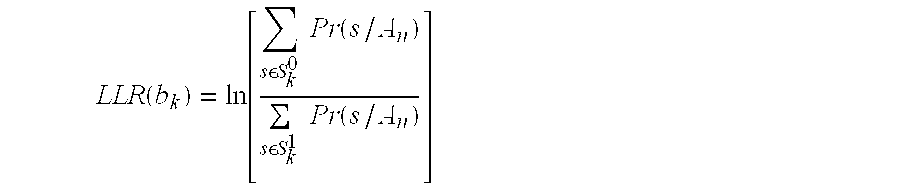
LLR computer block 456 computes 2log2M bit LLRs for each received soft QAM symbol. Due to the product symmetry of square QAM constellation and the Gray code mapping, the LLR of a particular code bit is a function of either An (the real portion) or Bn (the imaginary portion) and the corresponding one-dimensional PAM signal points. In other words, for the purpose of computing LLRs, the received QAM signal can be considered to be consisting of two independent PAM signals. Hence the LLR for a given code bit bk (k is the bit index within log2M group of bits or label representing a PAM signal; 0≦k≦log2M) corresponding to the received signal An, assuming equally likely modulation symbols, is given by
- where S k 0 and Sk 1 represents subsets of M-PAM signal points for which bk=0 and bk=1, respectively. As discussed above, due to preceding, the received soft decisions An and Bn belong to expanded PAM signal constellation. Thus, the LLR is determined by determining the probability that An was received given that s was transmitted. As illustrated in the last portion of equation (8), the LLR computation may incorporate affects of noise factors σ2.
- Performing a
Mod 2M operation on An and Bn folds the received signal point into the basic constellation, which is appropriate if the hard decision is to be performed on An and Bn. However, when the channel coding is present, which utilizes the soft decision to compute the bit LLR for turbo codes (or bit branch metric for soft decision Viterbi decoding of convolutional codes), then folding the received constellation before computing the bit LLR or branch metric results in a severe performance degradation of the decoder. This is exemplified in FIG. 5. - FIG. 5 illustrates a received modulo signal constellation and an expanded signal constellation.
Box 504 represents the modulo (unexpanded) signal constellation comprising of points −3, −1, 1, and 3, which correspond to gray codes (for bits b0 and b1), 11, 10, 00 and 01, respectively. If a point 508 is received as illustrated (just outside of “4”) and a modulo 2M operation were performed, point 508 translates to point 512 (just inside of −4). In an unexpanded constellation, the probability of point 512 being either a 0 or 1 is evaluated. The probability of bit b0 being “1” is extremely high, since the only near by value for bit b0 is “1” (say approximately a 95% probability). However, if the expanded signal constellation is considered, the probability of point 508 being either a 0 or 1 is evaluated. Since point 508 is slightly closer to “11” than “01”, the probability of bit b0 being “1” is much lower (say approximately a 55% probability). Thus, use of an expanded signal constellation before computing the LLR, and not using themodulo 2M operation, yields a significantly more accurate probability determination of the given bit. - Thus, the modification of eliminating the modulo operation and computing the bit LLR on the expanded signal constellation is used for computing the bit LLR or branch metric when a precoder is present. In other words, the set S k 0 and Sk 0 is expanded by adding 2Mi to each point in the original set where i is an integer. The LLR is then determined using the expanded set. The range of possible values of i needed to be considered from an ensemble of channel realizations is predetermined. Through simulation, it has been determined that using a large number of channel realizations that i=−2, −1, 0, 1, 2 is generally sufficient; however, it is contemplated than any value of i may be used. Assuming that the above range of i is sufficient, the cardinality of the expanded signal set Sk 0 and Sk 0 is four times larger than the original set. This increases the complexity of LLR computation significantly. However, this can be minimized if only those points that are within ±M of the received point for LLR or metric computation are considered.
- FIG. 6 illustrates a
flowchart 600 of the method by which the LLR is determined. A plurality of demodulated signal points is received 604. The demodulated signal points comprise a plurality of coded bits and noise. A first subset of signal points and a second subset of signal points are determined 608. Next, the probability of a given bit being received, given that a particular soft decision was received, is determined 612. The received soft decision belongs to the expanded signal constellation. Thus, as shown by equation (8), the LLR is determined 616 as the logarithm of the ratio of the summation of the probabilities that the bit received is a “1” or a “0”. - Antenna diversity, such as in a multiple input multiple output (MIMO) system, is a powerful scheme to improve the performance of data transmission over a fading channel. The preceding method described above, along with the determination of the LLR using the bit extended constellation, is equally suitable for communication systems employing multiple receive antenna diversity, either combining or selection diversity.
- Thus, a novel and improved method and apparatus for determining the LLR in conjunction with a precoder has been described. Those of skill in the art would understand that information and signals may be represented using any of a variety of different technologies and techniques. For example, data, instructions, commands, information, signals, bits, symbols, and chips that may be referenced throughout the above description may be represented by voltages, currents, electromagnetic waves, magnetic fields or particles, optical fields or particles, or any combination thereof.
- Those of skill would further appreciate that the various illustrative logical blocks, modules, circuits, and algorithm steps described in connection with the embodiments disclosed herein may be implemented as electronic hardware, computer software, or combinations of both. To clearly illustrate this interchangeability of hardware and software, various illustrative components, blocks, modules, circuits, and steps have been described above generally in terms of their functionality. Whether such functionality is implemented as hardware or software depends upon the particular application and design constraints imposed on the overall system. Skilled artisans may implement the described functionality in varying ways for each particular application, but such implementation decisions should not be interpreted as causing a departure from the scope of the present invention.
- The various illustrative logical blocks, modules, and circuits described in connection with the embodiments disclosed herein may be implemented or performed with a general purpose processor, a digital signal processor (DSP), an application specific integrated circuit (ASIC), a field programmable gate array (FPGA) or other programmable logic device, discrete gate or transistor logic, discrete hardware components, or any combination thereof designed to perform the functions described herein. A general purpose processor may be a microprocessor, but in the alternative, the processor may be any conventional processor, controller, microcontroller, or state machine. A processor may also be implemented as a combination of computing devices, e.g., a combination of a DSP and a microprocessor, a plurality of microprocessors, one or more microprocessors in conjunction with a DSP core, or any other such configuration.
- The steps of a method or algorithm described in connection with the embodiments disclosed herein may be embodied directly in hardware, in a software module executed by a processor, or in a combination of the two. A software module may reside in RAM memory, flash memory, ROM memory, EPROM memory, EEPROM memory, registers, hard disk, a removable disk, a CD-ROM, or any other form of storage medium known in the art. The processor and an associated storage medium may reside in an application specific integrated circuit (ASIC). The ASIC may reside in a subscriber unit, or in some form of wireless infrastructure. In the alternative, the processor and the storage medium may reside as discrete components in a user terminal.
- The previous description of the disclosed embodiments is provided to enable any person skilled in the art to make or use the present invention. Various modifications to these embodiments will be readily apparent to those skilled in the art, and the generic principles defined herein may be applied to other embodiments without departing from the spirit or scope of the invention. Thus, the present invention is not intended to be limited to the embodiments shown herein but is to be accorded the widest scope consistent with the principles and novel features disclosed herein.
Claims (43)


Priority Applications (1)
| Application Number | Priority Date | Filing Date | Title |
|---|---|---|---|
| US10/305,587 US7218689B2 (en) | 2001-11-29 | 2002-11-27 | Method and apparatus for determining the log-likelihood ratio with precoding |
Applications Claiming Priority (2)
| Application Number | Priority Date | Filing Date | Title |
|---|---|---|---|
| US33436301P | 2001-11-29 | 2001-11-29 | |
| US10/305,587 US7218689B2 (en) | 2001-11-29 | 2002-11-27 | Method and apparatus for determining the log-likelihood ratio with precoding |
Publications (2)
| Publication Number | Publication Date |
|---|---|
| US20030112901A1 true US20030112901A1 (en) | 2003-06-19 |
| US7218689B2 US7218689B2 (en) | 2007-05-15 |
Family
ID=23306875
Family Applications (1)
| Application Number | Title | Priority Date | Filing Date |
|---|---|---|---|
| US10/305,587 Expired - Fee Related US7218689B2 (en) | 2001-11-29 | 2002-11-27 | Method and apparatus for determining the log-likelihood ratio with precoding |
Country Status (16)
| Country | Link |
|---|---|
| US (1) | US7218689B2 (en) |
| EP (1) | EP1461924A4 (en) |
| JP (1) | JP4116562B2 (en) |
| KR (1) | KR100911424B1 (en) |
| CN (1) | CN100583860C (en) |
| AR (1) | AR039071A1 (en) |
| AU (1) | AU2002346605B2 (en) |
| BR (1) | BR0214528A (en) |
| CA (1) | CA2468574A1 (en) |
| IL (2) | IL162191A0 (en) |
| MX (1) | MXPA04005171A (en) |
| MY (1) | MY137160A (en) |
| RU (1) | RU2304352C2 (en) |
| TW (1) | TWI292272B (en) |
| WO (1) | WO2003047118A2 (en) |
| ZA (1) | ZA200404175B (en) |
Cited By (35)
| Publication number | Priority date | Publication date | Assignee | Title |
|---|---|---|---|---|
| US20030103584A1 (en) * | 2001-12-03 | 2003-06-05 | Bjerke Bjorn A. | Iterative detection and decoding for a MIMO-OFDM system |
| US20030185310A1 (en) * | 2002-03-27 | 2003-10-02 | Ketchum John W. | Precoding for a multipath channel in a MIMO system |
| US20040038653A1 (en) * | 2002-08-21 | 2004-02-26 | Holger Claussen | Radio telecommunications system operative by interactive determination of soft estimates, and a corresponding method |
| US20040042565A1 (en) * | 2002-08-30 | 2004-03-04 | David Garrett | Maximum likelihood a posteriori probability detector |
| GB2406759A (en) * | 2003-10-02 | 2005-04-06 | Toshiba Res Europ Ltd | Signal decoding using a probability distribution for each symbol transmitted over a MIMO channel |
| US20050122896A1 (en) * | 2003-11-12 | 2005-06-09 | Samsung Electronics Co., Ltd. | Apparatus and method for canceling interference signal in an orthogonal frequency division multiplexing system using multiple antennas |
| US20060067293A1 (en) * | 2004-09-24 | 2006-03-30 | John Santhoff | Digital synthesis of communication signals |
| US20060239366A1 (en) * | 2005-04-21 | 2006-10-26 | Joonsuk Kim | RF transceiver having adaptive modulation |
| US20070072606A1 (en) * | 2005-09-28 | 2007-03-29 | Pieter Van Rooyen | Method and system for mitigating interference from analog TV in a DVB-H system |
| US20070153714A1 (en) * | 2005-12-29 | 2007-07-05 | Nir Shapira | Device, system and method of securing wireless communication |
| US20070155353A1 (en) * | 2005-12-29 | 2007-07-05 | Nir Shapira | Method of secure WLAN communication |
| US20070191043A1 (en) * | 2005-12-29 | 2007-08-16 | Nir Shapira | Method of secure WLAN communication |
| US20070217536A1 (en) * | 2006-03-16 | 2007-09-20 | Joonsang Choi | Method and apparatus for calculating likelihood metric of a received signal in a digital communication system |
| US20080028277A1 (en) * | 2006-07-27 | 2008-01-31 | Samsung Electronics Co., Ltd. | Apparatus and method for correcting error in a multiple-input multiple-output communication system |
| WO2008121553A1 (en) * | 2007-03-29 | 2008-10-09 | Sandisk Corporation | Non-volatile storage with decoding of data using reliability metrics based on multiple reads |
| US20080250300A1 (en) * | 2007-03-29 | 2008-10-09 | Nima Mokhlesi | Method for decoding data in non-volatile storage using reliability metrics based on multiple reads |
| US20090076789A1 (en) * | 2005-11-09 | 2009-03-19 | Chung Shan Institute Of Science And Technology, Armaments Bureau, M.N.D. | Method for pre-verifying software/hardware design of communication system |
| US20090180566A1 (en) * | 2005-06-22 | 2009-07-16 | Tomohiro Kimura | Transmission apparatus and a reception apparatus in a multicarrier transmission system and a transmission method and a reception method using the multicarrier transmission system |
| US20110044412A1 (en) * | 2003-11-21 | 2011-02-24 | Panasonic Corporation | Multi-antenna reception apparatus, multi-antenna reception method, multi-antenna transmission apparatus and multi-antenna communication system |
| EP2297868A1 (en) * | 2008-07-07 | 2011-03-23 | Commonwealth Scientific and Industrial Research Organisation | Multiple-input multiple-output ofdm systems |
| US20110182277A1 (en) * | 2005-12-29 | 2011-07-28 | Nir Shapira | Method, apparatus and system of spatial division multiple access communication in a wireless local area network |
| US8073072B2 (en) | 2003-11-04 | 2011-12-06 | Qualcomm Atheros, Inc. | Multiple-input multiple-output system and method |
| CN102664707A (en) * | 2012-04-10 | 2012-09-12 | 华为技术有限公司 | Method for determining logarithm likelihood ratio, Turbo encoding method and device thereof |
| US8428169B1 (en) * | 2008-07-30 | 2013-04-23 | Marvell International Ltd. | MIMO soft demodulation using hard-decision candidate selection |
| US20130100833A1 (en) * | 2009-11-06 | 2013-04-25 | Hua Xu | Transmission of Information in a Wireless Communication System |
| US8542658B2 (en) * | 2006-01-11 | 2013-09-24 | Qualcomm Incorporated | Support for wide area networks and local area peer-to-peer networks |
| US8995518B1 (en) * | 2009-01-23 | 2015-03-31 | Pmc-Sierra, Inc. | Equalizer for heavily clipped or compressed communications signals |
| US9071435B2 (en) | 2005-12-29 | 2015-06-30 | Celeno Communications Ltd. | System and method for tuning transmission parameters in multi-user multiple-input-multiple-output systems with aged and noisy channel estimation |
| US9088345B2 (en) | 2009-08-21 | 2015-07-21 | Blackberry Limited | Transmission of information in a wireless communication system |
| US20170048841A1 (en) * | 2015-08-14 | 2017-02-16 | Mediatek Inc. | Signal Modulation and Demodulation for Multiuser Superposition Transmission Scheme |
| US10304550B1 (en) | 2017-11-29 | 2019-05-28 | Sandisk Technologies Llc | Sense amplifier with negative threshold sensing for non-volatile memory |
| US10643695B1 (en) | 2019-01-10 | 2020-05-05 | Sandisk Technologies Llc | Concurrent multi-state program verify for non-volatile memory |
| US10965396B2 (en) * | 2015-01-26 | 2021-03-30 | Saturn Licensing Llc | Receiver for receiving data in a broadcast system using redundancy data |
| US11024392B1 (en) | 2019-12-23 | 2021-06-01 | Sandisk Technologies Llc | Sense amplifier for bidirectional sensing of memory cells of a non-volatile memory |
| EP3920494A1 (en) * | 2020-06-05 | 2021-12-08 | Nokia Solutions and Networks Oy | Method and apparatus for reducing dfe-induced error propagation impact on soft-input decoding |
Families Citing this family (42)
| Publication number | Priority date | Publication date | Assignee | Title |
|---|---|---|---|---|
| US6711121B1 (en) * | 1998-10-09 | 2004-03-23 | At&T Corp. | Orthogonal code division multiplexing for twisted pair channels |
| US7002900B2 (en) | 2002-10-25 | 2006-02-21 | Qualcomm Incorporated | Transmit diversity processing for a multi-antenna communication system |
| DE60313505T2 (en) * | 2003-02-13 | 2007-12-27 | Ntt Docomo Inc. | DIFFERENTIAL TRANSMISSION AND RECEPTION DIVERSITY WITH MULTIPLE LENGTH |
| US8064528B2 (en) | 2003-05-21 | 2011-11-22 | Regents Of The University Of Minnesota | Estimating frequency-offsets and multi-antenna channels in MIMO OFDM systems |
| US7580480B2 (en) * | 2003-06-23 | 2009-08-25 | Hong-seok Seo | Demodulation method using soft decision for quadrature amplitude modulation and apparatus thereof |
| US7394858B2 (en) | 2003-08-08 | 2008-07-01 | Intel Corporation | Systems and methods for adaptive bit loading in a multiple antenna orthogonal frequency division multiplexed communication system |
| EP2536059B1 (en) * | 2003-09-09 | 2014-03-12 | NTT DoCoMo, Inc. | Signal transmitting method and transmitter in radio multiplex transmission system |
| US8204149B2 (en) | 2003-12-17 | 2012-06-19 | Qualcomm Incorporated | Spatial spreading in a multi-antenna communication system |
| US7194042B2 (en) * | 2004-01-13 | 2007-03-20 | Qualcomm Incorporated | Data transmission with spatial spreading in a mimo communication system |
| US10985811B2 (en) | 2004-04-02 | 2021-04-20 | Rearden, Llc | System and method for distributed antenna wireless communications |
| US11394436B2 (en) | 2004-04-02 | 2022-07-19 | Rearden, Llc | System and method for distributed antenna wireless communications |
| US11451275B2 (en) | 2004-04-02 | 2022-09-20 | Rearden, Llc | System and method for distributed antenna wireless communications |
| US8923785B2 (en) | 2004-05-07 | 2014-12-30 | Qualcomm Incorporated | Continuous beamforming for a MIMO-OFDM system |
| WO2006008565A1 (en) * | 2004-06-18 | 2006-01-26 | Nokia Corporation | Frequency domain equalization of frequency-selective mimo channels |
| GB2415336B (en) * | 2004-06-18 | 2006-11-08 | Toshiba Res Europ Ltd | Bit interleaver for a mimo system |
| US7978649B2 (en) | 2004-07-15 | 2011-07-12 | Qualcomm, Incorporated | Unified MIMO transmission and reception |
| US8484272B2 (en) * | 2004-08-20 | 2013-07-09 | Qualcomm Incorporated | Unified pulse shaping for multi-carrier and single-carrier waveforms |
| US8401503B2 (en) * | 2005-03-01 | 2013-03-19 | Qualcomm Incorporated | Dual-loop automatic frequency control for wireless communication |
| JP4733689B2 (en) * | 2005-03-09 | 2011-07-27 | 富士通株式会社 | Communication system and transmission method |
| EP1746756B1 (en) * | 2005-07-21 | 2013-01-16 | STMicroelectronics Srl | A method and system for decoding signals, corresponding receiver and computer program product |
| US7684522B2 (en) * | 2005-08-02 | 2010-03-23 | Beceem Communications Inc. | Method and system for determining a log-likelihood ratio (LLR) corresponding to each bit of a symbol |
| KR100788890B1 (en) | 2005-12-07 | 2007-12-27 | 한국전자통신연구원 | Transmitting Apparatus for transmitting in the multicarrier system using multiple antennas and Receiving Apparatus in the same system |
| US8811369B2 (en) | 2006-01-11 | 2014-08-19 | Qualcomm Incorporated | Methods and apparatus for supporting multiple communications modes of operation |
| US8331425B2 (en) * | 2006-02-28 | 2012-12-11 | Kyocera Corporation | Apparatus, system and method for providing a multiple input/multiple output (MIMO) channel interface |
| US20080016425A1 (en) * | 2006-04-04 | 2008-01-17 | Qualcomm Incorporated | Turbo decoder with symmetric and non-symmetric decoding rates |
| US8543070B2 (en) | 2006-04-24 | 2013-09-24 | Qualcomm Incorporated | Reduced complexity beam-steered MIMO OFDM system |
| CN1921366B (en) * | 2006-09-25 | 2010-07-21 | 华为技术有限公司 | Method and device for realizing coded identification log-likelihood ratio |
| CN103117975B (en) * | 2007-08-20 | 2017-05-24 | 瑞登有限责任公司 | System of compensating MU-MAS communications and dynamically adapting communication characteristics of MU-MAS communication system |
| KR101402305B1 (en) | 2008-01-21 | 2014-06-30 | 삼성전자주식회사 | Lattice aided detection method and apparatus with soft output in MIMO system |
| US8345793B2 (en) * | 2008-03-10 | 2013-01-01 | Telefonaktiebolaget Lm Ericsson (Publ) | Compensation of diagonal ISI in OFDM signals |
| US8391408B2 (en) * | 2008-05-06 | 2013-03-05 | Industrial Technology Research Institute | Method and apparatus for spatial mapping matrix searching |
| US8595501B2 (en) | 2008-05-09 | 2013-11-26 | Qualcomm Incorporated | Network helper for authentication between a token and verifiers |
| US8175189B2 (en) * | 2009-03-11 | 2012-05-08 | Hitachi, Ltd. | Fast generalized decision feedback equalizer precoder implementation for multi-user multiple-input multiple-output wireless transmission systems |
| US10194346B2 (en) | 2012-11-26 | 2019-01-29 | Rearden, Llc | Systems and methods for exploiting inter-cell multiplexing gain in wireless cellular systems via distributed input distributed output technology |
| US11190947B2 (en) | 2014-04-16 | 2021-11-30 | Rearden, Llc | Systems and methods for concurrent spectrum usage within actively used spectrum |
| US10164698B2 (en) | 2013-03-12 | 2018-12-25 | Rearden, Llc | Systems and methods for exploiting inter-cell multiplexing gain in wireless cellular systems via distributed input distributed output technology |
| US10547358B2 (en) | 2013-03-15 | 2020-01-28 | Rearden, Llc | Systems and methods for radio frequency calibration exploiting channel reciprocity in distributed input distributed output wireless communications |
| CN103166903B (en) * | 2013-03-19 | 2015-08-12 | 清华大学 | The soft solution preprocess method of constellation mapping and soft solution method |
| US11290162B2 (en) | 2014-04-16 | 2022-03-29 | Rearden, Llc | Systems and methods for mitigating interference within actively used spectrum |
| RU2577192C1 (en) * | 2015-02-11 | 2016-03-10 | Межрегиональное общественное учреждение "Институт инженерной физики" | Incoherent demodulator of binary digital signal with a soft iterative decoding of data |
| US10257844B2 (en) | 2017-01-17 | 2019-04-09 | Qualcomm Incorporated | Beam-combining scheme with broadcast beam-sweeping and beam-index indication |
| FR3084227B1 (en) * | 2018-07-23 | 2021-09-10 | Mohamed Tlich | MULTI-CHANNEL MICROWAVE RADIO MODEM BASED ON MULTI-CARRIER MODULATION |
Citations (11)
| Publication number | Priority date | Publication date | Assignee | Title |
|---|---|---|---|---|
| US5040191A (en) * | 1987-02-24 | 1991-08-13 | Codex Corporation | Partial response channel signaling systems |
| US5446763A (en) * | 1991-07-02 | 1995-08-29 | Motorola, Inc. | Apparatus and method for converting soft symbols into soft bits |
| US6026122A (en) * | 1994-04-01 | 2000-02-15 | Fujitsu Limited | Process and system for transferring vector signal with precoding for signal power reduction |
| US6145114A (en) * | 1997-08-14 | 2000-11-07 | Her Majesty The Queen In Right Of Canada, As Represented By The Minister Of Industry Through Communications Research Centre | Method of enhanced max-log-a posteriori probability processing |
| US6188717B1 (en) * | 1996-11-19 | 2001-02-13 | Deutsche Forschungsanstalt Fur Luft-Und Raumfahrt E.V. | Method of simultaneous radio transmission of digital data between a plurality of subscriber stations and a base station |
| US6215831B1 (en) * | 1995-03-31 | 2001-04-10 | Motorola, Inc. | Decoder circuit using bit-wise probability and method therefor |
| US6272183B1 (en) * | 1997-08-22 | 2001-08-07 | Siemens Aktiengesellschaft | Method for data transmission on transmission channels in a digital transmission system |
| US6282168B1 (en) * | 1997-06-19 | 2001-08-28 | Qualcomm Inc. | Bit interleaving for orthogonal frequency division multiplexing in the transmission of digital signals |
| US6499128B1 (en) * | 1999-02-18 | 2002-12-24 | Cisco Technology, Inc. | Iterated soft-decision decoding of block codes |
| US20030147655A1 (en) * | 1999-11-02 | 2003-08-07 | Shattil Steve J. | Unified multi-carrier framework for multiple-access technologies |
| US6944242B2 (en) * | 2001-01-04 | 2005-09-13 | Comsys Communication & Signal Processing Ltd. | Apparatus for and method of converting soft symbol information to soft bit information |
Family Cites Families (3)
| Publication number | Priority date | Publication date | Assignee | Title |
|---|---|---|---|---|
| US5095497A (en) * | 1989-10-02 | 1992-03-10 | At & T Bell Laboratories | Technique for achieving the full coding gain of encoded digital signals |
| US5311547A (en) * | 1992-02-03 | 1994-05-10 | At&T Bell Laboratories | Partial-response-channel precoding |
| GB2355164B (en) * | 1999-10-07 | 2004-06-09 | Oak Technology Inc | Demodulator circuit |
-
2002
- 2002-11-27 MX MXPA04005171A patent/MXPA04005171A/en active IP Right Grant
- 2002-11-27 US US10/305,587 patent/US7218689B2/en not_active Expired - Fee Related
- 2002-11-27 CN CN02827429A patent/CN100583860C/en not_active Expired - Fee Related
- 2002-11-27 CA CA002468574A patent/CA2468574A1/en not_active Abandoned
- 2002-11-27 KR KR1020047008191A patent/KR100911424B1/en not_active IP Right Cessation
- 2002-11-27 EP EP02784678A patent/EP1461924A4/en not_active Withdrawn
- 2002-11-27 AU AU2002346605A patent/AU2002346605B2/en not_active Ceased
- 2002-11-27 JP JP2003548417A patent/JP4116562B2/en not_active Expired - Fee Related
- 2002-11-27 IL IL16219102A patent/IL162191A0/en unknown
- 2002-11-27 WO PCT/US2002/038341 patent/WO2003047118A2/en active Application Filing
- 2002-11-27 BR BR0214528-6A patent/BR0214528A/en not_active IP Right Cessation
- 2002-11-27 RU RU2004119550/09A patent/RU2304352C2/en not_active IP Right Cessation
- 2002-11-28 MY MYPI20024456A patent/MY137160A/en unknown
- 2002-11-29 TW TW091134790A patent/TWI292272B/en active
- 2002-11-29 AR ARP020104624A patent/AR039071A1/en active IP Right Grant
-
2004
- 2004-05-27 IL IL162191A patent/IL162191A/en not_active IP Right Cessation
- 2004-05-27 ZA ZA200404175A patent/ZA200404175B/en unknown
Patent Citations (11)
| Publication number | Priority date | Publication date | Assignee | Title |
|---|---|---|---|---|
| US5040191A (en) * | 1987-02-24 | 1991-08-13 | Codex Corporation | Partial response channel signaling systems |
| US5446763A (en) * | 1991-07-02 | 1995-08-29 | Motorola, Inc. | Apparatus and method for converting soft symbols into soft bits |
| US6026122A (en) * | 1994-04-01 | 2000-02-15 | Fujitsu Limited | Process and system for transferring vector signal with precoding for signal power reduction |
| US6215831B1 (en) * | 1995-03-31 | 2001-04-10 | Motorola, Inc. | Decoder circuit using bit-wise probability and method therefor |
| US6188717B1 (en) * | 1996-11-19 | 2001-02-13 | Deutsche Forschungsanstalt Fur Luft-Und Raumfahrt E.V. | Method of simultaneous radio transmission of digital data between a plurality of subscriber stations and a base station |
| US6282168B1 (en) * | 1997-06-19 | 2001-08-28 | Qualcomm Inc. | Bit interleaving for orthogonal frequency division multiplexing in the transmission of digital signals |
| US6145114A (en) * | 1997-08-14 | 2000-11-07 | Her Majesty The Queen In Right Of Canada, As Represented By The Minister Of Industry Through Communications Research Centre | Method of enhanced max-log-a posteriori probability processing |
| US6272183B1 (en) * | 1997-08-22 | 2001-08-07 | Siemens Aktiengesellschaft | Method for data transmission on transmission channels in a digital transmission system |
| US6499128B1 (en) * | 1999-02-18 | 2002-12-24 | Cisco Technology, Inc. | Iterated soft-decision decoding of block codes |
| US20030147655A1 (en) * | 1999-11-02 | 2003-08-07 | Shattil Steve J. | Unified multi-carrier framework for multiple-access technologies |
| US6944242B2 (en) * | 2001-01-04 | 2005-09-13 | Comsys Communication & Signal Processing Ltd. | Apparatus for and method of converting soft symbol information to soft bit information |
Cited By (76)
| Publication number | Priority date | Publication date | Assignee | Title |
|---|---|---|---|---|
| US20030103584A1 (en) * | 2001-12-03 | 2003-06-05 | Bjerke Bjorn A. | Iterative detection and decoding for a MIMO-OFDM system |
| US7154936B2 (en) * | 2001-12-03 | 2006-12-26 | Qualcomm, Incorporated | Iterative detection and decoding for a MIMO-OFDM system |
| US20080212657A1 (en) * | 2001-12-03 | 2008-09-04 | Qualcomm Incorporated | Iterative detection and decoding for a mimo-ofdm system |
| US20050157811A1 (en) * | 2001-12-03 | 2005-07-21 | Bjerke Bjorn A. | Iterative detection and decoding for a MIMO-OFDM system |
| US20030185310A1 (en) * | 2002-03-27 | 2003-10-02 | Ketchum John W. | Precoding for a multipath channel in a MIMO system |
| US7197084B2 (en) * | 2002-03-27 | 2007-03-27 | Qualcomm Incorporated | Precoding for a multipath channel in a MIMO system |
| US20040038653A1 (en) * | 2002-08-21 | 2004-02-26 | Holger Claussen | Radio telecommunications system operative by interactive determination of soft estimates, and a corresponding method |
| US7248647B2 (en) * | 2002-08-21 | 2007-07-24 | Lucent Technologies Inc. | Radio telecommunications system operative by interactive determination of soft estimates, and a corresponding method |
| US20040042565A1 (en) * | 2002-08-30 | 2004-03-04 | David Garrett | Maximum likelihood a posteriori probability detector |
| US7609777B2 (en) * | 2002-08-30 | 2009-10-27 | Alcatel-Lucent Usa Inc. | Maximum likelihood a posteriori probability detector |
| GB2406759B (en) * | 2003-10-02 | 2006-06-07 | Toshiba Res Europ Ltd | Signal decoding methods and apparatus |
| CN100399733C (en) * | 2003-10-02 | 2008-07-02 | 株式会社东芝 | Signal decoding method and apparatus |
| US20050089112A1 (en) * | 2003-10-02 | 2005-04-28 | Kabushiki Kaisha Toshiba | Signal decoding methods and apparatus |
| GB2406759A (en) * | 2003-10-02 | 2005-04-06 | Toshiba Res Europ Ltd | Signal decoding using a probability distribution for each symbol transmitted over a MIMO channel |
| US8073072B2 (en) | 2003-11-04 | 2011-12-06 | Qualcomm Atheros, Inc. | Multiple-input multiple-output system and method |
| US8599953B2 (en) | 2003-11-04 | 2013-12-03 | Qualcomm Incorporated | Multiple-input multiple-output system and method |
| US8989294B2 (en) | 2003-11-04 | 2015-03-24 | Qualcomm Incorporated | Multiple-input multiple-output system and method |
| US20050122896A1 (en) * | 2003-11-12 | 2005-06-09 | Samsung Electronics Co., Ltd. | Apparatus and method for canceling interference signal in an orthogonal frequency division multiplexing system using multiple antennas |
| US20110044412A1 (en) * | 2003-11-21 | 2011-02-24 | Panasonic Corporation | Multi-antenna reception apparatus, multi-antenna reception method, multi-antenna transmission apparatus and multi-antenna communication system |
| US20120147989A1 (en) * | 2003-11-21 | 2012-06-14 | Panasonic Corporation | Interleaver, interleaving method, transmission apparatus, and transmitting method |
| US8144799B2 (en) * | 2003-11-21 | 2012-03-27 | Panasonic Corporation | Multi-antenna reception apparatus, multi-antenna reception method, multi-antenna transmission apparatus and multi-antenna communication system |
| US8724729B2 (en) * | 2003-11-21 | 2014-05-13 | Harris Corporation | Interleaver, interleaving method, transmission apparatus, and transmitting method |
| US20060067293A1 (en) * | 2004-09-24 | 2006-03-30 | John Santhoff | Digital synthesis of communication signals |
| US20060239366A1 (en) * | 2005-04-21 | 2006-10-26 | Joonsuk Kim | RF transceiver having adaptive modulation |
| US7502408B2 (en) * | 2005-04-21 | 2009-03-10 | Broadcom Corporation | RF transceiver having adaptive modulation |
| US8199838B2 (en) | 2005-06-22 | 2012-06-12 | Panasonic Corporation | Transmission apparatus and a reception apparatus in a multicarrier transmission system and a transmission method and a reception method using the multicarrier transmission system |
| US20090180566A1 (en) * | 2005-06-22 | 2009-07-16 | Tomohiro Kimura | Transmission apparatus and a reception apparatus in a multicarrier transmission system and a transmission method and a reception method using the multicarrier transmission system |
| US8090034B2 (en) | 2005-06-22 | 2012-01-03 | Panasonic Corporation | Transmission apparatus and a reception apparatus in a multicarrier transmission system and a transmission method and a reception method using the multicarrier transmission system |
| US20070072606A1 (en) * | 2005-09-28 | 2007-03-29 | Pieter Van Rooyen | Method and system for mitigating interference from analog TV in a DVB-H system |
| US20090076789A1 (en) * | 2005-11-09 | 2009-03-19 | Chung Shan Institute Of Science And Technology, Armaments Bureau, M.N.D. | Method for pre-verifying software/hardware design of communication system |
| US9345001B2 (en) | 2005-12-29 | 2016-05-17 | Celeno Communications Ltd. | Method, apparatus and system of spatial division multiple access communication in a wireless local area network |
| US7672400B2 (en) | 2005-12-29 | 2010-03-02 | Celeno Communications (Israel) Ltd. | Method of secure WLAN communication |
| US7751353B2 (en) * | 2005-12-29 | 2010-07-06 | Celeno Communications (Israel) Ltd. | Device, system and method of securing wireless communication |
| US20070155353A1 (en) * | 2005-12-29 | 2007-07-05 | Nir Shapira | Method of secure WLAN communication |
| US8532078B2 (en) | 2005-12-29 | 2013-09-10 | Celeno Communications Ltd. | Method, apparatus and system of spatial division multiple access communication in a wireless local area network |
| US20070153714A1 (en) * | 2005-12-29 | 2007-07-05 | Nir Shapira | Device, system and method of securing wireless communication |
| US7656965B2 (en) | 2005-12-29 | 2010-02-02 | Celeno Communications (Israel) Ltd. | Method of secure WLAN communication |
| US20070191043A1 (en) * | 2005-12-29 | 2007-08-16 | Nir Shapira | Method of secure WLAN communication |
| US20110182277A1 (en) * | 2005-12-29 | 2011-07-28 | Nir Shapira | Method, apparatus and system of spatial division multiple access communication in a wireless local area network |
| US9071435B2 (en) | 2005-12-29 | 2015-06-30 | Celeno Communications Ltd. | System and method for tuning transmission parameters in multi-user multiple-input-multiple-output systems with aged and noisy channel estimation |
| US8902860B2 (en) | 2006-01-11 | 2014-12-02 | Qualcomm Incorporated | Wireless communication methods and apparatus using beacon signals |
| US8542658B2 (en) * | 2006-01-11 | 2013-09-24 | Qualcomm Incorporated | Support for wide area networks and local area peer-to-peer networks |
| US8553644B2 (en) | 2006-01-11 | 2013-10-08 | Qualcomm Incorporated | Wireless communication methods and apparatus supporting different types of wireless communication approaches |
| US20070217536A1 (en) * | 2006-03-16 | 2007-09-20 | Joonsang Choi | Method and apparatus for calculating likelihood metric of a received signal in a digital communication system |
| WO2007105925A1 (en) * | 2006-03-16 | 2007-09-20 | Posdata Co., Ltd. | Method and apparatus for calculating likelihood metric of a received signal in a digital communication system |
| US7586991B2 (en) * | 2006-03-16 | 2009-09-08 | Posdata Co., Ltd. | Method and apparatus for calculating likelihood metric of a received signal in a digital communication system |
| US20080028277A1 (en) * | 2006-07-27 | 2008-01-31 | Samsung Electronics Co., Ltd. | Apparatus and method for correcting error in a multiple-input multiple-output communication system |
| US7966545B2 (en) | 2006-07-27 | 2011-06-21 | Samsung Electronics Co., Ltd | Apparatus and method for correcting error in a multiple-input multiple-output communication system |
| US8966350B2 (en) | 2007-03-29 | 2015-02-24 | Sandisk Technologies Inc. | Providing reliability metrics for decoding data in non-volatile storage |
| US8468424B2 (en) | 2007-03-29 | 2013-06-18 | Sandisk Technologies Inc. | Method for decoding data in non-volatile storage using reliability metrics based on multiple reads |
| TWI397076B (en) * | 2007-03-29 | 2013-05-21 | Sandisk Technologies Inc | Method and system for decoding data in non-volatile storage using reliability metrics based on multiple reads |
| US20110131473A1 (en) * | 2007-03-29 | 2011-06-02 | Sandisk Corporation | Method For Decoding Data In Non-Volatile Storage Using Reliability Metrics Based On Multiple Reads |
| US20080250300A1 (en) * | 2007-03-29 | 2008-10-09 | Nima Mokhlesi | Method for decoding data in non-volatile storage using reliability metrics based on multiple reads |
| WO2008121553A1 (en) * | 2007-03-29 | 2008-10-09 | Sandisk Corporation | Non-volatile storage with decoding of data using reliability metrics based on multiple reads |
| US7904793B2 (en) | 2007-03-29 | 2011-03-08 | Sandisk Corporation | Method for decoding data in non-volatile storage using reliability metrics based on multiple reads |
| EP2297868A1 (en) * | 2008-07-07 | 2011-03-23 | Commonwealth Scientific and Industrial Research Organisation | Multiple-input multiple-output ofdm systems |
| EP2297868A4 (en) * | 2008-07-07 | 2014-08-06 | Commw Scient Ind Res Org | Multiple-input multiple-output ofdm systems |
| US8644433B1 (en) * | 2008-07-30 | 2014-02-04 | Marvell International Ltd. | MIMO soft demodulation using hard-decision candidate selection |
| US8428169B1 (en) * | 2008-07-30 | 2013-04-23 | Marvell International Ltd. | MIMO soft demodulation using hard-decision candidate selection |
| US8995518B1 (en) * | 2009-01-23 | 2015-03-31 | Pmc-Sierra, Inc. | Equalizer for heavily clipped or compressed communications signals |
| US9088345B2 (en) | 2009-08-21 | 2015-07-21 | Blackberry Limited | Transmission of information in a wireless communication system |
| US10123310B2 (en) | 2009-08-21 | 2018-11-06 | Blackberry Limited | Transmission of information in a wireless communication system |
| US11337185B2 (en) | 2009-08-21 | 2022-05-17 | Blackberry Limited | Transmission of information in a wireless communication system |
| US10645678B2 (en) | 2009-08-21 | 2020-05-05 | Blackberry Limited | Transmission of information in a wireless communication system |
| US9660786B2 (en) | 2009-08-21 | 2017-05-23 | Blackberry Limited | Transmission of information in a wireless communication system |
| US9814003B2 (en) * | 2009-11-06 | 2017-11-07 | Blackberry Limited | Transmission of information in a wireless communication system |
| US20130100833A1 (en) * | 2009-11-06 | 2013-04-25 | Hua Xu | Transmission of Information in a Wireless Communication System |
| CN102664707A (en) * | 2012-04-10 | 2012-09-12 | 华为技术有限公司 | Method for determining logarithm likelihood ratio, Turbo encoding method and device thereof |
| US10965396B2 (en) * | 2015-01-26 | 2021-03-30 | Saturn Licensing Llc | Receiver for receiving data in a broadcast system using redundancy data |
| US10050683B2 (en) * | 2015-08-14 | 2018-08-14 | Mediatek Inc. | Signal modulation and demodulation for multiuser superposition transmission scheme |
| US10257013B2 (en) | 2015-08-14 | 2019-04-09 | Hfi Innovation, Inc. | Signal modulation and demodulation for multiuser superposition transmission scheme |
| US20170048841A1 (en) * | 2015-08-14 | 2017-02-16 | Mediatek Inc. | Signal Modulation and Demodulation for Multiuser Superposition Transmission Scheme |
| US10304550B1 (en) | 2017-11-29 | 2019-05-28 | Sandisk Technologies Llc | Sense amplifier with negative threshold sensing for non-volatile memory |
| US10643695B1 (en) | 2019-01-10 | 2020-05-05 | Sandisk Technologies Llc | Concurrent multi-state program verify for non-volatile memory |
| US11024392B1 (en) | 2019-12-23 | 2021-06-01 | Sandisk Technologies Llc | Sense amplifier for bidirectional sensing of memory cells of a non-volatile memory |
| EP3920494A1 (en) * | 2020-06-05 | 2021-12-08 | Nokia Solutions and Networks Oy | Method and apparatus for reducing dfe-induced error propagation impact on soft-input decoding |
Also Published As
| Publication number | Publication date |
|---|---|
| RU2004119550A (en) | 2005-11-10 |
| BR0214528A (en) | 2004-12-28 |
| US7218689B2 (en) | 2007-05-15 |
| MXPA04005171A (en) | 2004-08-11 |
| IL162191A (en) | 2010-11-30 |
| AU2002346605B2 (en) | 2008-09-11 |
| JP4116562B2 (en) | 2008-07-09 |
| EP1461924A4 (en) | 2010-07-07 |
| IL162191A0 (en) | 2005-11-20 |
| AU2002346605A1 (en) | 2003-06-10 |
| CN100583860C (en) | 2010-01-20 |
| KR20040061005A (en) | 2004-07-06 |
| CN1615622A (en) | 2005-05-11 |
| CA2468574A1 (en) | 2003-06-05 |
| KR100911424B1 (en) | 2009-08-11 |
| EP1461924A2 (en) | 2004-09-29 |
| WO2003047118A2 (en) | 2003-06-05 |
| WO2003047118A3 (en) | 2003-11-27 |
| TWI292272B (en) | 2008-01-01 |
| TW200304309A (en) | 2003-09-16 |
| RU2304352C2 (en) | 2007-08-10 |
| JP2005510939A (en) | 2005-04-21 |
| ZA200404175B (en) | 2005-08-11 |
| MY137160A (en) | 2009-01-30 |
| AR039071A1 (en) | 2005-02-09 |
Similar Documents
| Publication | Publication Date | Title |
|---|---|---|
| US7218689B2 (en) | Method and apparatus for determining the log-likelihood ratio with precoding | |
| US7359313B2 (en) | Space-time bit-interleaved coded modulation for wideband transmission | |
| Zhou et al. | Single-carrier space-time block-coded transmissions over frequency-selective fading channels | |
| KR101280734B1 (en) | Incremental redundancy transmission in a mimo communication system | |
| US7586992B2 (en) | Apparatus and method for channel estimation and cyclic prefix reconstruction in an OFDM-STBC mobile communication system | |
| US20100296556A1 (en) | Method and transceiver using blind channel estimation | |
| US20030073464A1 (en) | Space-time coded transmissions within a wireless communication network | |
| Berardinelli et al. | Improving SC-FDMA performance by turbo equalization in UTRA LTE uplink | |
| US20040170228A1 (en) | Frequency domain partial response signaling with high spectral efficiency and low peak to average power ratio | |
| Yang et al. | Bayesian Monte Carlo multiuser receiver for space-time coded multicarrier CDMA systems | |
| EP1416688A1 (en) | Iterative channel estimation in multicarrier receivers | |
| US9660709B1 (en) | Systems and methods for calculating log-likelihood ratios in a MIMO detector | |
| EP1724959A1 (en) | Multiple access communication system with ARQ and interference cancellation | |
| Moon et al. | Channel estimation for MIMO-OFDM systems employing spatial multiplexing | |
| Dinis et al. | Soft combining ARQ techniques for wireless systems employing SC-FDE schemes | |
| Serra Pagès | A Long Term Evolution Link Level Simulator | |
| Mathews et al. | Performance of turbo coded FBMC based MIMO systems | |
| Arslan et al. | Physical layer evolution for GSM/EDGE | |
| Sondhi et al. | Performance Analysis of Cyclic Prefix and Zero Padding Equalization Technique for MIMO-OFDM System | |
| Jang et al. | An efficient symbol-level combining scheme for MIMO systems with hybrid ARQ | |
| Dinis et al. | SC-FDE with soft packet combining ARQ techniques for interference-limited UWB systems | |
| Nickel et al. | Turbo equalization for single antenna cochannel interference cancellation in single carrier transmission systems | |
| Hoefel et al. | Performance of IEEE 802.11 n with time-frequency impairments over flat fading channels | |
| Armando et al. | Frequency Domain Turbo Equalization for Single Carrier Space-Time Block Code PER Block | |
| Montezuma et al. | Frequency-Domain Packet Combining Techniques for UWB |
Legal Events
| Date | Code | Title | Description |
|---|---|---|---|
| AS | Assignment |
Owner name: QUALCOMM INCORPORATED, CALIFORNIA Free format text: ASSIGNMENT OF ASSIGNORS INTEREST;ASSIGNOR:GUPTA, ALOK KUMAR;REEL/FRAME:013538/0064 Effective date: 20021127 |
|
| STCF | Information on status: patent grant |
Free format text: PATENTED CASE |
|
| FPAY | Fee payment |
Year of fee payment: 4 |
|
| FPAY | Fee payment |
Year of fee payment: 8 |
|
| FEPP | Fee payment procedure |
Free format text: MAINTENANCE FEE REMINDER MAILED (ORIGINAL EVENT CODE: REM.); ENTITY STATUS OF PATENT OWNER: LARGE ENTITY |
|
| LAPS | Lapse for failure to pay maintenance fees |
Free format text: PATENT EXPIRED FOR FAILURE TO PAY MAINTENANCE FEES (ORIGINAL EVENT CODE: EXP.); ENTITY STATUS OF PATENT OWNER: LARGE ENTITY |
|
| STCH | Information on status: patent discontinuation |
Free format text: PATENT EXPIRED DUE TO NONPAYMENT OF MAINTENANCE FEES UNDER 37 CFR 1.362 |
|
| FP | Lapsed due to failure to pay maintenance fee |
Effective date: 20190515 |