US20020184874A1 - Pivot fairing thrust reverser - Google Patents
Pivot fairing thrust reverser Download PDFInfo
- Publication number
- US20020184874A1 US20020184874A1 US09/877,826 US87782601A US2002184874A1 US 20020184874 A1 US20020184874 A1 US 20020184874A1 US 87782601 A US87782601 A US 87782601A US 2002184874 A1 US2002184874 A1 US 2002184874A1
- Authority
- US
- United States
- Prior art keywords
- doors
- fairings
- thrust reverser
- aft
- pivots
- Prior art date
- Legal status (The legal status is an assumption and is not a legal conclusion. Google has not performed a legal analysis and makes no representation as to the accuracy of the status listed.)
- Granted
Links
Images


Classifications
-
- F—MECHANICAL ENGINEERING; LIGHTING; HEATING; WEAPONS; BLASTING
- F02—COMBUSTION ENGINES; HOT-GAS OR COMBUSTION-PRODUCT ENGINE PLANTS
- F02K—JET-PROPULSION PLANTS
- F02K1/00—Plants characterised by the form or arrangement of the jet pipe or nozzle; Jet pipes or nozzles peculiar thereto
- F02K1/54—Nozzles having means for reversing jet thrust
- F02K1/56—Reversing jet main flow
- F02K1/62—Reversing jet main flow by blocking the rearward discharge by means of flaps
- F02K1/625—Reversing jet main flow by blocking the rearward discharge by means of flaps the aft end of the engine cowling being movable to uncover openings for the reversed flow
-
- F—MECHANICAL ENGINEERING; LIGHTING; HEATING; WEAPONS; BLASTING
- F02—COMBUSTION ENGINES; HOT-GAS OR COMBUSTION-PRODUCT ENGINE PLANTS
- F02K—JET-PROPULSION PLANTS
- F02K1/00—Plants characterised by the form or arrangement of the jet pipe or nozzle; Jet pipes or nozzles peculiar thereto
- F02K1/54—Nozzles having means for reversing jet thrust
- F02K1/56—Reversing jet main flow
- F02K1/60—Reversing jet main flow by blocking the rearward discharge by means of pivoted eyelids or clamshells, e.g. target-type reversers
-
- Y—GENERAL TAGGING OF NEW TECHNOLOGICAL DEVELOPMENTS; GENERAL TAGGING OF CROSS-SECTIONAL TECHNOLOGIES SPANNING OVER SEVERAL SECTIONS OF THE IPC; TECHNICAL SUBJECTS COVERED BY FORMER USPC CROSS-REFERENCE ART COLLECTIONS [XRACs] AND DIGESTS
- Y02—TECHNOLOGIES OR APPLICATIONS FOR MITIGATION OR ADAPTATION AGAINST CLIMATE CHANGE
- Y02T—CLIMATE CHANGE MITIGATION TECHNOLOGIES RELATED TO TRANSPORTATION
- Y02T50/00—Aeronautics or air transport
- Y02T50/60—Efficient propulsion technologies, e.g. for aircraft
Definitions
- the present invention relates generally to aircraft engines, and, more specifically, to thrust reversers therefor.
- Turbofan gas turbine engines are commonly used for powering aircraft in flight.
- air is pressurized in a compressor and mixed with fuel and ignited in a combustor for generating hot combustion gases which flow downstream through turbines which extract energy therefrom.
- a high pressure turbine powers the compressor, and a low pressure turbine powers the fan disposed upstream of the compressor.
- Propulsion thrust is provided by the combination of the hot combustion gas exhaust from the core engine with the pressurized fan air which bypasses the core engine.
- the fan air bypasses the core engine inside a surrounding nacelle and is mixed with the core exhaust prior to discharge from the engine in a combined exhaust stream.
- thrust reversers With the engine in which doors are selectively opened for blocking the aft direction of the engine exhaust and redirecting it in the forward direction for providing additional braking for the aircraft.
- thrust reversers There are two basic types of thrust reversers having doors mounted either post-exit to the discharge exhaust nozzle, or pre-exit from that outlet nozzle.
- thrust reversers are used solely during aircraft landing they must be integrated into the engine with minimal adverse effect during all remaining conditions of operation including takeoff, cruise, and descent.
- the prior art is quite crowded with myriad forms of thrust reversers attempting to minimize adverse affects thereof while maximizing aerodynamic performance of the engine.
- a post-exit thrust reverser includes a pair of clamshell doors which are deployed in the form of an open clamshell for redirecting the engine exhaust in the forward direction during landing. Since the deployed clamshell doors must closely adjoin each other at their trailing edges, when the doors are retracted or stowed, the trailing edges thereof typically form a fishmouth configuration which introduces undesirable aerodynamic drag during normal operation of the engine. Drag is a performance penalty which reduces overall efficiency of the engine with this type of thrust reverser.
- the reverser doors are located upstream from the discharge end of the nozzle resulting in a typically more complex configuration for integrating the doors in the stowed and deployed positions thereof.
- the stowed doors must minimize aerodynamic losses of the exhaust channelled therethrough during normal operation, as well as providing a streamlined outer surface for reducing drag thereover.
- the doors should be suitably sealed to the exhaust nozzle when stowed for reducing or minimizing exhaust gas leakage through the convoluted perimeter of the doors.
- each of the two doors must be suitably arcuate to match the annular configuration of the nozzle when stowed.
- the two doors are thusly arcuate at their forward and aft ends with relatively straight side edges therebetween, and with inner and outer surfaces which must suitably blend with corresponding inner and outer surfaces of the exhaust duct in which they are mounted.
- thrust reversers Yet another significant design factor for thrust reversers is the integration with the actuating means of suitable safety devices for preventing unintended deployment of the thrust reversers except for aircraft landing. Such deployment prevention must be integrated with the actuating means without introducing excessive weight penalty, yet providing a durable and rugged thrust reverser actuation system for long life thereof.
- a thrust reverser includes a pair of doors covering corresponding portals in an exhaust duct between an inlet and outlet nozzle at opposite ends thereof.
- the duct also includes a pair of side beams having actuators mounted thereon, and operatively joined to the doors for selective rotation thereof about corresponding pivots.
- Blister fairings are disposed inside the duct and sealingly join the doors to the beams around respective ones of the pivots.
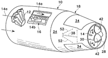
- FIG. 1 is isometric view of an exemplary turbofan gas turbine aircraft engine having a thrust reverser mounted at the aft end thereof in accordance with the present invention.
- FIG. 2 is isometric view of the thrust reverser illustrated in FIG. 1 with doors thereof being deployed open in accordance with an exemplary embodiment of the present invention.
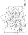
- FIG. 3 is a partly sectional, side elevational view of the thrust reverser illustrated in FIG. 2 with the upper door being deployed open and the lower door being illustrated retracted closed in its stowed position for direct comparison.
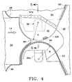
- FIG. 4 is a partly sectional, side elevational view of two door pivots and covering blister fairings in accordance with an exemplary embodiment as viewed generally along line 4 - 4 inside the exhaust duct illustrated in FIG. 1.
- FIG. 5 is an elevational sectional view through the door pivot and blister fairing illustrated in FIG. 4 and taken along line 5 - 5 .
- FIG. 1 Illustrated in FIG. 1 is a gas turbine engine 10 in the exemplary form of a turbofan engine configured for powering an aircraft in flight.
- the engine is configured for being side-mounted to the fuselage of an aircraft near the tail thereof.
- the engine may have any conventional configuration and typically includes a single stage fan 12 having rotor blades through which ambient air 14 a enters the engine during operation.
- the fan is powered by a core engine 16 having a compressor that pressurizes a portion of the fan air which is then mixed with fuel and ignited in a combustor for generating hot combustion gases 14 b which are discharged through corresponding high and low pressure turbines disposed downstream therefrom.
- the high pressure turbine powers the compressor through a shaft therebetween, and the low pressure turbine powers the fan through another shaft therebetween.
- the fan air bypasses the core engine inside a corresponding bypass duct defined between the outer nacelle of the engine and the outer casing of the core engine and mixes with the combustion gases at the aft end of the engine prior to discharge as a common exhaust stream 14 through an annular thrust reverser 18 mounted to the aft end of the engine.
- the engine may have any conventional configuration and is operated in a conventional manner for powering an aircraft from takeoff, cruise, descent, and landing.
- the thrust reverser 18 is provided for use only during landing of the aircraft for providing braking reverse thrust for assisting and stopping the aircraft along the runway.
- the thrust reverser 18 in accordance with an exemplary embodiment of the present invention is illustrated closed in FIG. 1 and opened in FIG. 2 in isolation from the engine.
- the thrust reverser includes a generally annular exhaust duct 20 having an axial centerline axis 22 therethrough.
- the exhaust duct defines the outer boundary for discharging the fan and gas streams in the common exhaust stream 14 , and is surrounded by a suitable external fairing 24 which blends smoothly with the external surface of the engine nacelle for reducing friction drag thereover during operation.
- the exhaust duct 20 includes an inlet 26 at the upstream end thereof for receiving the exhaust 14 from the engine.
- An annular outlet or discharge nozzle 28 is disposed at the opposite, axially downstream end of the exhaust duct for discharging the exhaust therefrom during normal operation of the engine for forward propulsion in flight.
- the exhaust duct also includes a pair of diametrically opposite side beams 30 extending axially between the inlet and nozzle ends of the duct on the horizontal left and right sides thereof.
- a pair of diametrically opposite side outlets or portals 32 are disposed circumferentially between the side beams and spaced forward from the outlet nozzle 28 .
- the two portals are disposed in the top and bottom sides of the exhaust duct and extend in an arc between the two side beams for providing upper and lower side outlets for the exhaust flow during operation of the thrust reverser.
- Thrust reversing operation is effected by a pair of thrust reverser doors 34 disposed in respective ones of the portals, with each door having a generally arcuate shape in the typical form of clamshell thrust reverser doors.
- the individual doors may be formed in any conventional manner including inner and outer skins with reinforcing ribs therebetween.
- the exhaust duct 20 may also be configured in any conventional form with a smooth inner skin for bounding the exhaust during operation, and surrounded by the external fairing 24 which preferably has removable panels for accessing internal features of the thrust reverser.
- each of the two doors 34 is rotatably mounted at opposite circumferential sides thereof to the two side beams by corresponding pivots 36 .
- Each door thusly includes two pivots disposed on the sides thereof upstream from the trailing edge of the door, which define a single pivot axis for swinging open or closed the individual doors in their respective portals.
- each of the pivots 36 is in the preferred form of an inner support arm 36 a fixedly joined to a respective side beam by suitable fasteners for example, and extending vertically upwardly or downwardly in the form of a cantilever therefrom.
- Each pivot also includes an outer support arm 36 b fixedly joined to a respective door on opposite sides thereof and spaced upstream from the trailing edge of the door.
- a fastener 36 c pivotally joins together the respective pairs of inner and outer arms in any conventional manner for permitting each door to pivot open and close around a corresponding single pivot axis thereof.
- actuating means include a pair of side actuators 38 fixedly mounted on respective ones of the two side beams and operatively joined to the doors for selective rotation thereof about the pivots to deploy the doors during thrust reverser operation and stow the doors for all other normal operation of the engine when thrust reverse is not required.
- the actuators are operatively joined to a suitable controller 40 configured for controlling all operation of the thrust reverser as required.
- the actuators 38 may be hydraulically powered, and the controller 40 is configured for extending or retracting the output rods of the actuators for pivoting open or closed the doors as desired.
- each door 34 closes the corresponding portal 32 when stowed, with the external surface thereof blending smoothly with the external fairing of the thrust reverser. Since the thrust reverser is annular, the two doors are arcuate in the circumferential direction over the required extent to close the portals.
- the doors preferably have upstream edges which overlap corresponding upstream portions of the duct in front of the portals, and downstream portions which underlap upstream edges of the outlet nozzle 28 at the aft end of the corresponding portals.
- the individual doors are rotated around the respective pivots 36 during deployment for opening the forward portions of the portals and redirecting the exhaust 14 radially outwardly therefrom in the general forward direction during thrust reverse operation.
- the aft ends of the doors are correspondingly pivoted together inside the exhaust nozzle wherein they adjoin each other as illustrated in FIG. 2 to form the typical clamshell configuration with an obtuse included angle therebetween for discharging the exhaust out the upper and lower portals during thrust reverse operation.
- the doors may abut each other when open, or may have a small gap therebetween in accordance with conventional deployment practice.
- Single-pivot clamshell thrust reverser doors like those illustrated in FIG. 3, are particularly difficult to seal at the corresponding pivots due to the rotary movement of the doors within the corresponding portals.
- two pairs of blister fairings 42 as initially shown in FIGS. 1 - 3 are disposed inside the exhaust duct and sealingly join the doors to the side beams around respective ones of the four pivots 36 .
- the blister fairings 42 provide means for covering the four pivots inside the exhaust duct for sealing closed each of the doors at each of the pivots notwithstanding the rotary motion of each door required for deployment and retraction. Sealing of the pivot joints is particularly important when the doors are stowed for reducing or preventing leakage of the exhaust flow therethrough which would decrease the propulsion efficiency of the exhaust discharged through the exhaust nozzle.
- each of the blister fairings 42 includes a proximal border 42 a fixedly and sealingly joined to the inside of a respective door outboard of the pivot 36 .
- each fairing includes an arcuate opposite distal border 42 b which is cantilevered away from the door edge and overlaps a respective side beam along the inner surface thereof.
- the distal border 42 b forms a portion of a circle having a radius A with a center of curvature corresponding with the respective center of the pivot 36 for rotating thereabout. In this way, as each door rotates around the pivot 36 during deployment or retraction, the attached blister fairing also rotates therewith relative to the stationary side beam 30 .
- Each blister fairing thusly covers the inner surface of the respective pivots and provides an aerodynamically smooth flowpath along which the exhaust 14 is discharged during operation.
- an arcuate fairing seal 44 is fixedly mounted to the inner surface of the side beams around each of the four pivots in sliding sealing abutment with the arcuate distal borders 42 b of corresponding ones of the blister fairings for providing four corresponding rotary seals therewith.
- the fairing seals 44 have a radius of curvature B measured from the center of the respective pivots 36 , which seal radius B is slightly less than the border radius A of the fairing for providing a rotary slide seal therebetween as the doors pivot when actuated.
- the fairing border 42 b is thusly concentric with the arcuate fairing seal 44 for maintaining continuity of the seal therebetween.
- each fairing seal may have any suitable form for providing a sliding seal between the blister fairing and the inner surface of the side beam 30 .
- each fairing seal may be formed of a suitable elastomeric material such as silicone covered with a low friction fabric such as polytetrafluoroethylene (PTFE), commonly known as Teflon, which seal materials are common in thrust reversers.
- PTFE polytetrafluoroethylene
- the seal is suitably trapped or secured in a metal supporting strip which is suitably fixedly joined to the side beam by fasteners or rivets for example.
- the inner surface of the exhaust duct is generally circular except at the side beams 30 which are generally flat for mounting the actuators to the external surfaces thereof.
- the side beams may be arcuate, and, for example, may match the inner diameter of the exhaust duct.
- the fairing seals 44 are preferably mounted on locally flat inner surfaces of the side beams 30 to sealingly abut the correspondingly flat inner surfaces of the fairing distal borders 42 b. In this way, when the doors are stowed in their closed positions, the distal borders of each of the blister fairings sealingly engages the corresponding fairing seals 44 to reduce or eliminate any exhaust flow leakage therethrough for normal operation of the engine.
- the fairing distal borders may match the fairing seals in an arcuate abutting fit, like a spherical joint, for providing a contact seal therebetween which permits relative movement between the fairing and seal during door deployment.
- the exhaust 14 is confined to flow out the discharge nozzle 28 for maximum propulsion efficiency and with little if any leakage around the four pivot joints of the closed doors.
- the sliding joint formed between the fairing borders and the fairing seals permit relative movement therebetween without obstruction between the blister fairings and the side beams.
- the fairing seals additionally seal against exhaust flow leakage around the pivot joints during thrust reverse operation for maximizing efficiency thereof.
- the side beams 30 preferably include corresponding steps or recesses 46 disposed forward of the respective blister fairings 42 for mounting the fairings substantially flush in the recesses, with the corresponding fairing seals 44 being recessed below the blister fairings and the flat plateau or step provided upstream of the recess.
- the exhaust 14 flows downstream along the flat inner surface of the side beams 30 , it may smoothly flow over the inner surface of the respective blister fairings 42 disposed substantially flush therewith.
- the blister fairings thusly do not create upstream facing steps which would increase drag losses in the exhaust being discharged through the exhaust duct.
- each of the doors 34 includes a forward perimeter disposed forward of the two blister fairings at the corresponding pivots 36 thereof.
- the door forward perimeter is arcuate along the leading edge of the door and generally straight along the two side edges of the door extending aft to the two pivots.
- the inside or inner surface of the forward door perimeter matches the corresponding configuration of the outer surface of the exhaust duct 20 around the forward portion of the corresponding portals.
- each door includes an aft perimeter disposed aft of the two blister fairings thereof, which is arcuate along the trailing edge of each door and generally straight along the two side edges of each door forward to the corresponding pivots.
- the outer surface of the door aft perimeter is suitably configured for underlapping the corresponding inner surface of the outlet nozzle 28 at the aft end of each portal.
- the duct preferably also includes an aft seal 50 surrounding each of the portals aft of the blister fairings and within the inner edge of the external fairing. In this way, when the doors are stowed closed as illustrated in the bottom half of FIG. 3, the aft perimeter of each door sealingly engages the aft seal 50 at the upstream end of the exhaust nozzle.
- the forward and aft seals 48 , 50 are preferably continuous strips having any suitable seal configuration such as conventional silicone wipers or leaf seals encased by a fabric of low friction material like PTFE.
- the forward seal 48 surrounds the forward portion of each portal up to the forward end of each blister fairing
- the aft seal 50 surrounds the aft portion of each portal up to the aft end of each blister fairing
- the forward and aft seals preferably adjoin opposite ends of the respective fairing seals 44 to provide substantially full-perimeter sealing of each of the doors when stowed closed.
- Each blister fairing covers the inner surface of each pivot joint and provides the arcuate border for maintaining continuity of the door seal between the forward and aft seals 48 , 50 .
- Each door is thusly fully sealed when closed, yet may be pivoted open without compromising performance of the blister fairings 42 and the cooperating fairing seals 44 .
- the door actuating means preferably also include two pairs of actuator rods or links 52 pivotally joined at opposite ends to respective ones of the two doors 34 forward of the corresponding pivots thereof, and to the two side actuators 38 for selectively rotating open and closed the doors around the corresponding pivots.
- each actuator link 52 is pivotally joined to a corresponding support arm extending from the side of the door in an integral assembly with the outer arm 36 b.
- each blister fairing 42 is sized and configured to additionally cover corresponding ends of the links joined to the door.
- each of the two doors 34 is joined at opposite sides thereof to respective ones of the two actuators 38 by the corresponding two actuator links 52 .
- the actuator output rod is retracted or extended, the proximal ends of the four links 52 travel therewith for pivoting open or closed the respective doors around the corresponding pivots 36 .
- the upper door 34 is illustrated deployed with the corresponding actuator link 52 being pushed outwardly, and the inner door 34 is illustrated stowed with the corresponding actuator link 52 being withdrawn inwardly.
- the kinematic motion of the actuator, cooperating links, and single-pivot doors may be derived from that disclosed in substantial detail in U.S. Pat. No. 4,422,605-Fage, incorporated herein by reference.
- This actuation system has several advantages including effective deployment of the two doors, and safe locking thereof in their stowed positions.
- the two doors are interconnected to each other by the four actuator links 52 and the two common actuators 38 . This provides redundancy in both deploying the doors as well as maintaining the doors safely stowed in their closed positions.
- each of the doors 34 as illustrated in FIG. 3 may include a pair of outer hooks 54 fixedly mounted to the forward ends thereof at the circumferentially opposite sides. And, a pair of inner hooks or latches 56 are pivotally mounted to each of the two side beams 30 for selectively latching respective ones of the outer hooks 54 to prevent deployment of the doors when not intended.
- the two inner latches 56 are suitably joined to a latch actuator 58 , which is preferably hydraulically driven, for pivoting the latches either clockwise or counterclockwise when desired.
- a latch actuator 58 which is preferably hydraulically driven, for pivoting the latches either clockwise or counterclockwise when desired.
- the inner latch 56 has been rotated counterclockwise for releasing the corresponding outer hook 54 to deploy the corresponding door.
- a particular advantage of the latching means illustrated in FIG. 3 is that the two latches 56 prevent deployment of the doors from the stowed position unless the two doors are firstly superetracted or overstowed by operation of the corresponding door actuators 38 prior to reversing those door actuators to deploy the doors. Since the inner latches 56 have a general J-configuration, they cannot be disconnected from the cooperating outer hooks until those outer hooks are driven inwardly toward the center of the exhaust nozzle for permitting the J-latches to clear the outer hooks. Accordingly, the controller 40 is configured for initially driving the door actuators 38 to superetract the doors from their closed and stowed positions for permitting unlatching of the inner latches 56 prior to reversing direction of the door actuators to deploy the doors.
- a particular advantage of the pre-exit type of thrust reverser illustrated in FIGS. 1 - 3 is the optimum forward thrust performance thereof attributable to the downstream located exhaust nozzle 28 .
- the trailing edge of the exhaust nozzle 28 is coplanar and substantially normal to the centerline axis 22 for substantially reducing aerodynamic losses or base drag during operation, which losses and drag are typically found in conventional fishmouth exhaust outlets.
- the exhaust nozzle 28 is preferably circular at its trailing edge as illustrated in FIGS. 1 and 2 for maximizing propulsion efficiency, and blends forward therefrom with the flat inner surfaces of the two side beams 30 as best illustrated in FIGS. 1 and 4.
- the two side beams 30 are preferably flat for mounting the common actuators 38 and the cooperating actuator links 52 as illustrated in FIG. 3 and thusly interrupt the circular continuity inside the exhaust duct.
- the inner surfaces of the flat side beams may blend at both their upstream and downstream ends to smoothly transition to the fully circular inner surface of the exhaust duct at the opposite inlet and outlet ends thereof.
- each of the blister fairings 42 blends from the flat inner surfaces of the side beams to the arcuate inner surface of the respective doors 34 at the proximal borders 42 a of the individual fairings.
- Each of the blister fairings 42 is preferably sized and configured to cover respective ones of the door pivots 36 for providing effective seals therearound, with forward and aft continuity with the forward and aft seals 48 , 50 .
- the blister fairings may have a suitable dome configuration for covering the inside of the door joints, and may be made of any suitable material such as metal, or preferably lightweight graphite and epoxy composite.
- the exposed inner surface of each blister fairing should aerodynamically blend with the inner surfaces of the respective doors and side beams for providing an aerodynamically smooth boundary for discharging the exhaust through the outlet duct.
- the improved thrust reverser described above has enhanced forward thrust performance due to the blister fairings, low base drag, and the safety of the single-pivot side actuation and overstow feature.
- the single-pivot side actuation of the two doors has proven experience in the field for durable and rugged operation.
- the blister fairings effectively seal the door pivots for maximizing performance and efficiency.
Landscapes
- Engineering & Computer Science (AREA)
- Chemical & Material Sciences (AREA)
- Combustion & Propulsion (AREA)
- Mechanical Engineering (AREA)
- General Engineering & Computer Science (AREA)
- Power-Operated Mechanisms For Wings (AREA)
- Turbine Rotor Nozzle Sealing (AREA)
- Seal Device For Vehicle (AREA)
- Sealing Devices (AREA)
- Specific Sealing Or Ventilating Devices For Doors And Windows (AREA)
- Exhaust-Gas Circulating Devices (AREA)
Abstract
Description
- The present invention relates generally to aircraft engines, and, more specifically, to thrust reversers therefor.
- Turbofan gas turbine engines are commonly used for powering aircraft in flight. In a turbofan engine, air is pressurized in a compressor and mixed with fuel and ignited in a combustor for generating hot combustion gases which flow downstream through turbines which extract energy therefrom. A high pressure turbine powers the compressor, and a low pressure turbine powers the fan disposed upstream of the compressor.
- Propulsion thrust is provided by the combination of the hot combustion gas exhaust from the core engine with the pressurized fan air which bypasses the core engine. In a long duct turbofan engine, the fan air bypasses the core engine inside a surrounding nacelle and is mixed with the core exhaust prior to discharge from the engine in a combined exhaust stream.
- During aircraft landing, it is common to employ thrust reversers with the engine in which doors are selectively opened for blocking the aft direction of the engine exhaust and redirecting it in the forward direction for providing additional braking for the aircraft. There are two basic types of thrust reversers having doors mounted either post-exit to the discharge exhaust nozzle, or pre-exit from that outlet nozzle.
- Since thrust reversers are used solely during aircraft landing they must be integrated into the engine with minimal adverse effect during all remaining conditions of operation including takeoff, cruise, and descent. However, in view of the attendant complexity in providing thrust reversers at the discharge end of the engine, the prior art is quite crowded with myriad forms of thrust reversers attempting to minimize adverse affects thereof while maximizing aerodynamic performance of the engine.
- Since an aircraft engine is specifically configured for powering an aircraft in flight, engine weight is a primary design factor, and the introduction of a thrust reverser should minimize the corresponding increase in engine weight. Propulsion efficiency of the engine is yet another significant design factor, which is also adversely affected by the introduction of thrust reversers in various forms.
- For example, a post-exit thrust reverser includes a pair of clamshell doors which are deployed in the form of an open clamshell for redirecting the engine exhaust in the forward direction during landing. Since the deployed clamshell doors must closely adjoin each other at their trailing edges, when the doors are retracted or stowed, the trailing edges thereof typically form a fishmouth configuration which introduces undesirable aerodynamic drag during normal operation of the engine. Drag is a performance penalty which reduces overall efficiency of the engine with this type of thrust reverser.
- In pre-exit type thrust reversers, the reverser doors are located upstream from the discharge end of the nozzle resulting in a typically more complex configuration for integrating the doors in the stowed and deployed positions thereof. In particular, the stowed doors must minimize aerodynamic losses of the exhaust channelled therethrough during normal operation, as well as providing a streamlined outer surface for reducing drag thereover. And, the doors should be suitably sealed to the exhaust nozzle when stowed for reducing or minimizing exhaust gas leakage through the convoluted perimeter of the doors.
- Since the exhaust nozzle is annular in configuration, each of the two doors must be suitably arcuate to match the annular configuration of the nozzle when stowed. The two doors are thusly arcuate at their forward and aft ends with relatively straight side edges therebetween, and with inner and outer surfaces which must suitably blend with corresponding inner and outer surfaces of the exhaust duct in which they are mounted.
- Adding to the complexity of thrust reverser design is the inherent necessity for suitable actuation thereof for deploying open the doors when required and retracting closed the doors to their stowed positions when not required for aircraft landing. Various forms of actuators are found in the prior art having different advantages and disadvantages, which also increase the complexity of effective sealing of the doors.
- Yet another significant design factor for thrust reversers is the integration with the actuating means of suitable safety devices for preventing unintended deployment of the thrust reversers except for aircraft landing. Such deployment prevention must be integrated with the actuating means without introducing excessive weight penalty, yet providing a durable and rugged thrust reverser actuation system for long life thereof.
- Accordingly, it is desired to provide an improved thrust reverser with integrated components for enhancing aerodynamic performance in a compact and rugged assembly.
- A thrust reverser includes a pair of doors covering corresponding portals in an exhaust duct between an inlet and outlet nozzle at opposite ends thereof. The duct also includes a pair of side beams having actuators mounted thereon, and operatively joined to the doors for selective rotation thereof about corresponding pivots. Blister fairings are disposed inside the duct and sealingly join the doors to the beams around respective ones of the pivots.
- The invention, in accordance with preferred and exemplary embodiments, together with further objects and advantages thereof, is more particularly described in the following detailed description taken in conjunction with the accompanying drawings in which:
- FIG. 1 is isometric view of an exemplary turbofan gas turbine aircraft engine having a thrust reverser mounted at the aft end thereof in accordance with the present invention.
- FIG. 2 is isometric view of the thrust reverser illustrated in FIG. 1 with doors thereof being deployed open in accordance with an exemplary embodiment of the present invention.
- FIG. 3 is a partly sectional, side elevational view of the thrust reverser illustrated in FIG. 2 with the upper door being deployed open and the lower door being illustrated retracted closed in its stowed position for direct comparison.
- FIG. 4 is a partly sectional, side elevational view of two door pivots and covering blister fairings in accordance with an exemplary embodiment as viewed generally along line 4-4 inside the exhaust duct illustrated in FIG. 1.
- FIG. 5 is an elevational sectional view through the door pivot and blister fairing illustrated in FIG. 4 and taken along line 5-5.
- Illustrated in FIG. 1 is a
gas turbine engine 10 in the exemplary form of a turbofan engine configured for powering an aircraft in flight. In this exemplary embodiment the engine is configured for being side-mounted to the fuselage of an aircraft near the tail thereof. - The engine may have any conventional configuration and typically includes a
single stage fan 12 having rotor blades through whichambient air 14 a enters the engine during operation. The fan is powered by acore engine 16 having a compressor that pressurizes a portion of the fan air which is then mixed with fuel and ignited in a combustor for generatinghot combustion gases 14 b which are discharged through corresponding high and low pressure turbines disposed downstream therefrom. The high pressure turbine powers the compressor through a shaft therebetween, and the low pressure turbine powers the fan through another shaft therebetween. - The fan air bypasses the core engine inside a corresponding bypass duct defined between the outer nacelle of the engine and the outer casing of the core engine and mixes with the combustion gases at the aft end of the engine prior to discharge as a
common exhaust stream 14 through an annular thrust reverser 18 mounted to the aft end of the engine. But for the thrust reverser 18, the engine may have any conventional configuration and is operated in a conventional manner for powering an aircraft from takeoff, cruise, descent, and landing. - Accordingly, the
thrust reverser 18 is provided for use only during landing of the aircraft for providing braking reverse thrust for assisting and stopping the aircraft along the runway. - The thrust reverser 18 in accordance with an exemplary embodiment of the present invention is illustrated closed in FIG. 1 and opened in FIG. 2 in isolation from the engine. As initially shown in FIG. 2, the thrust reverser includes a generally
annular exhaust duct 20 having anaxial centerline axis 22 therethrough. The exhaust duct defines the outer boundary for discharging the fan and gas streams in thecommon exhaust stream 14, and is surrounded by a suitableexternal fairing 24 which blends smoothly with the external surface of the engine nacelle for reducing friction drag thereover during operation. - The
exhaust duct 20 includes aninlet 26 at the upstream end thereof for receiving theexhaust 14 from the engine. An annular outlet ordischarge nozzle 28 is disposed at the opposite, axially downstream end of the exhaust duct for discharging the exhaust therefrom during normal operation of the engine for forward propulsion in flight. - As shown in FIGS. 1 and 2, the exhaust duct also includes a pair of diametrically
opposite side beams 30 extending axially between the inlet and nozzle ends of the duct on the horizontal left and right sides thereof. - A pair of diametrically opposite side outlets or
portals 32 are disposed circumferentially between the side beams and spaced forward from theoutlet nozzle 28. The two portals are disposed in the top and bottom sides of the exhaust duct and extend in an arc between the two side beams for providing upper and lower side outlets for the exhaust flow during operation of the thrust reverser. - Thrust reversing operation is effected by a pair of
thrust reverser doors 34 disposed in respective ones of the portals, with each door having a generally arcuate shape in the typical form of clamshell thrust reverser doors. The individual doors may be formed in any conventional manner including inner and outer skins with reinforcing ribs therebetween. And, theexhaust duct 20 may also be configured in any conventional form with a smooth inner skin for bounding the exhaust during operation, and surrounded by theexternal fairing 24 which preferably has removable panels for accessing internal features of the thrust reverser. - As shown in FIGS. 2 and 3, each of the two
doors 34 is rotatably mounted at opposite circumferential sides thereof to the two side beams bycorresponding pivots 36. Each door thusly includes two pivots disposed on the sides thereof upstream from the trailing edge of the door, which define a single pivot axis for swinging open or closed the individual doors in their respective portals. - As shown in FIG. 3, each of the
pivots 36 is in the preferred form of aninner support arm 36 a fixedly joined to a respective side beam by suitable fasteners for example, and extending vertically upwardly or downwardly in the form of a cantilever therefrom. Each pivot also includes anouter support arm 36 b fixedly joined to a respective door on opposite sides thereof and spaced upstream from the trailing edge of the door. Afastener 36 c pivotally joins together the respective pairs of inner and outer arms in any conventional manner for permitting each door to pivot open and close around a corresponding single pivot axis thereof. - As shown in FIGS. 2 and 3, means are provided for actuating the doors for selectively deploying open and retracting closed the doors around the corresponding pivots. In the preferred embodiment illustrated the actuating means include a pair of
side actuators 38 fixedly mounted on respective ones of the two side beams and operatively joined to the doors for selective rotation thereof about the pivots to deploy the doors during thrust reverser operation and stow the doors for all other normal operation of the engine when thrust reverse is not required. - As shown schematically in FIG. 3, the actuators are operatively joined to a
suitable controller 40 configured for controlling all operation of the thrust reverser as required. For example, theactuators 38 may be hydraulically powered, and thecontroller 40 is configured for extending or retracting the output rods of the actuators for pivoting open or closed the doors as desired. - As shown in FIG. 1 and in the bottom half of FIG. 3, each
door 34 closes the correspondingportal 32 when stowed, with the external surface thereof blending smoothly with the external fairing of the thrust reverser. Since the thrust reverser is annular, the two doors are arcuate in the circumferential direction over the required extent to close the portals. The doors preferably have upstream edges which overlap corresponding upstream portions of the duct in front of the portals, and downstream portions which underlap upstream edges of theoutlet nozzle 28 at the aft end of the corresponding portals. - As shown in FIG. 2 and in the upper half of FIG. 3, the individual doors are rotated around the
respective pivots 36 during deployment for opening the forward portions of the portals and redirecting theexhaust 14 radially outwardly therefrom in the general forward direction during thrust reverse operation. The aft ends of the doors are correspondingly pivoted together inside the exhaust nozzle wherein they adjoin each other as illustrated in FIG. 2 to form the typical clamshell configuration with an obtuse included angle therebetween for discharging the exhaust out the upper and lower portals during thrust reverse operation. The doors may abut each other when open, or may have a small gap therebetween in accordance with conventional deployment practice. - Single-pivot clamshell thrust reverser doors, like those illustrated in FIG. 3, are particularly difficult to seal at the corresponding pivots due to the rotary movement of the doors within the corresponding portals.
- However, and in accordance with the present invention, two pairs of
blister fairings 42 as initially shown in FIGS. 1-3 are disposed inside the exhaust duct and sealingly join the doors to the side beams around respective ones of the four pivots 36. The blister fairings 42 provide means for covering the four pivots inside the exhaust duct for sealing closed each of the doors at each of the pivots notwithstanding the rotary motion of each door required for deployment and retraction. Sealing of the pivot joints is particularly important when the doors are stowed for reducing or preventing leakage of the exhaust flow therethrough which would decrease the propulsion efficiency of the exhaust discharged through the exhaust nozzle. - As best illustrated in FIG. 4, each of the
blister fairings 42 includes aproximal border 42 a fixedly and sealingly joined to the inside of a respective door outboard of thepivot 36. And, each fairing includes an arcuate oppositedistal border 42 b which is cantilevered away from the door edge and overlaps a respective side beam along the inner surface thereof. Thedistal border 42 b forms a portion of a circle having a radius A with a center of curvature corresponding with the respective center of thepivot 36 for rotating thereabout. In this way, as each door rotates around thepivot 36 during deployment or retraction, the attached blister fairing also rotates therewith relative to thestationary side beam 30. - Each blister fairing thusly covers the inner surface of the respective pivots and provides an aerodynamically smooth flowpath along which the
exhaust 14 is discharged during operation. In the preferred embodiment illustrated in FIGS. 4 and 5, anarcuate fairing seal 44 is fixedly mounted to the inner surface of the side beams around each of the four pivots in sliding sealing abutment with the arcuatedistal borders 42 b of corresponding ones of the blister fairings for providing four corresponding rotary seals therewith. The fairing seals 44 have a radius of curvature B measured from the center of therespective pivots 36, which seal radius B is slightly less than the border radius A of the fairing for providing a rotary slide seal therebetween as the doors pivot when actuated. The fairingborder 42 b is thusly concentric with thearcuate fairing seal 44 for maintaining continuity of the seal therebetween. - As shown in FIG. 5, each fairing seal may have any suitable form for providing a sliding seal between the blister fairing and the inner surface of the
side beam 30. For example, each fairing seal may be formed of a suitable elastomeric material such as silicone covered with a low friction fabric such as polytetrafluoroethylene (PTFE), commonly known as Teflon, which seal materials are common in thrust reversers. The seal is suitably trapped or secured in a metal supporting strip which is suitably fixedly joined to the side beam by fasteners or rivets for example. - As initially illustrated in FIG. 1, the inner surface of the exhaust duct is generally circular except at the side beams 30 which are generally flat for mounting the actuators to the external surfaces thereof. In other embodiments, the side beams may be arcuate, and, for example, may match the inner diameter of the exhaust duct.
- As shown in FIG. 4, the fairing seals 44 are preferably mounted on locally flat inner surfaces of the side beams 30 to sealingly abut the correspondingly flat inner surfaces of the fairing
distal borders 42 b. In this way, when the doors are stowed in their closed positions, the distal borders of each of the blister fairings sealingly engages the corresponding fairing seals 44 to reduce or eliminate any exhaust flow leakage therethrough for normal operation of the engine. - In another embodiment of the sealed joints, the fairing distal borders may match the fairing seals in an arcuate abutting fit, like a spherical joint, for providing a contact seal therebetween which permits relative movement between the fairing and seal during door deployment.
- Accordingly, the
exhaust 14 is confined to flow out thedischarge nozzle 28 for maximum propulsion efficiency and with little if any leakage around the four pivot joints of the closed doors. However, when the doors are deployed to their open position, the sliding joint formed between the fairing borders and the fairing seals permit relative movement therebetween without obstruction between the blister fairings and the side beams. And, the fairing seals additionally seal against exhaust flow leakage around the pivot joints during thrust reverse operation for maximizing efficiency thereof. - As shown in FIGS. 4 and 5, the side beams 30 preferably include corresponding steps or recesses 46 disposed forward of the
respective blister fairings 42 for mounting the fairings substantially flush in the recesses, with the corresponding fairing seals 44 being recessed below the blister fairings and the flat plateau or step provided upstream of the recess. In this way as theexhaust 14 flows downstream along the flat inner surface of the side beams 30, it may smoothly flow over the inner surface of therespective blister fairings 42 disposed substantially flush therewith. The blister fairings thusly do not create upstream facing steps which would increase drag losses in the exhaust being discharged through the exhaust duct. - As shown in FIGS. 2 and 3, each of the
doors 34 includes a forward perimeter disposed forward of the two blister fairings at the correspondingpivots 36 thereof. The door forward perimeter is arcuate along the leading edge of the door and generally straight along the two side edges of the door extending aft to the two pivots. The inside or inner surface of the forward door perimeter matches the corresponding configuration of the outer surface of theexhaust duct 20 around the forward portion of the corresponding portals. - Fixedly mounted to the outer surface of the exhaust duct is a cooperating forward seal 48 surrounding each of the
portals 32 forward of therespective blister fairings 42 for abutting and sealing the door forward perimeter when stowed in the closed position as illustrated in the bottom half of FIG. 3. - Correspondingly, each door includes an aft perimeter disposed aft of the two blister fairings thereof, which is arcuate along the trailing edge of each door and generally straight along the two side edges of each door forward to the corresponding pivots. The outer surface of the door aft perimeter is suitably configured for underlapping the corresponding inner surface of the
outlet nozzle 28 at the aft end of each portal. The duct preferably also includes anaft seal 50 surrounding each of the portals aft of the blister fairings and within the inner edge of the external fairing. In this way, when the doors are stowed closed as illustrated in the bottom half of FIG. 3, the aft perimeter of each door sealingly engages theaft seal 50 at the upstream end of the exhaust nozzle. - The forward and aft seals 48,50 are preferably continuous strips having any suitable seal configuration such as conventional silicone wipers or leaf seals encased by a fabric of low friction material like PTFE.
- As shown in FIGS. 2 and 4, the
forward seal 48 surrounds the forward portion of each portal up to the forward end of each blister fairing, and theaft seal 50 surrounds the aft portion of each portal up to the aft end of each blister fairing, and the forward and aft seals preferably adjoin opposite ends of the respective fairing seals 44 to provide substantially full-perimeter sealing of each of the doors when stowed closed. Each blister fairing covers the inner surface of each pivot joint and provides the arcuate border for maintaining continuity of the door seal between the forward and aft seals 48,50. Each door is thusly fully sealed when closed, yet may be pivoted open without compromising performance of theblister fairings 42 and the cooperating fairing seals 44. - In the preferred embodiment illustrated in FIGS. 2 and 3, the door actuating means preferably also include two pairs of actuator rods or
links 52 pivotally joined at opposite ends to respective ones of the twodoors 34 forward of the corresponding pivots thereof, and to the twoside actuators 38 for selectively rotating open and closed the doors around the corresponding pivots. As shown in FIG. 3, eachactuator link 52 is pivotally joined to a corresponding support arm extending from the side of the door in an integral assembly with theouter arm 36 b. And, each blister fairing 42 is sized and configured to additionally cover corresponding ends of the links joined to the door. - In this way, each of the two
doors 34 is joined at opposite sides thereof to respective ones of the twoactuators 38 by the corresponding twoactuator links 52. As the actuator output rod is retracted or extended, the proximal ends of the fourlinks 52 travel therewith for pivoting open or closed the respective doors around the corresponding pivots 36. In FIG. 3, theupper door 34 is illustrated deployed with the correspondingactuator link 52 being pushed outwardly, and theinner door 34 is illustrated stowed with the correspondingactuator link 52 being withdrawn inwardly. - The kinematic motion of the actuator, cooperating links, and single-pivot doors may be derived from that disclosed in substantial detail in U.S. Pat. No. 4,422,605-Fage, incorporated herein by reference. This actuation system has several advantages including effective deployment of the two doors, and safe locking thereof in their stowed positions. For example, the two doors are interconnected to each other by the four
actuator links 52 and the twocommon actuators 38. This provides redundancy in both deploying the doors as well as maintaining the doors safely stowed in their closed positions. - Additional redundancy in locking closed the two doors in the stowed position is provided by additional means specifically configured for selectively latching closed the two doors, and unlatching the doors only after the doors are overstowed or superetracted. For example, each of the
doors 34 as illustrated in FIG. 3 may include a pair ofouter hooks 54 fixedly mounted to the forward ends thereof at the circumferentially opposite sides. And, a pair of inner hooks or latches 56 are pivotally mounted to each of the twoside beams 30 for selectively latching respective ones of theouter hooks 54 to prevent deployment of the doors when not intended. - The two
inner latches 56 are suitably joined to alatch actuator 58, which is preferably hydraulically driven, for pivoting the latches either clockwise or counterclockwise when desired. In the top of FIG. 3, theinner latch 56 has been rotated counterclockwise for releasing the correspondingouter hook 54 to deploy the corresponding door. - And, the
inner latch 56 in the bottom half of FIG. 3 has been rotated counterclockwise to engage the correspondingouter hook 54 and lock closed thecorresponding door 34 in its stowed position. The two deployed and stowed positions are illustrated together in FIG. 3 for clarity of presentation, with it being understood that the two doors are either deployed open or stowed closed together in normal operation. - A particular advantage of the latching means illustrated in FIG. 3 is that the two
latches 56 prevent deployment of the doors from the stowed position unless the two doors are firstly superetracted or overstowed by operation of thecorresponding door actuators 38 prior to reversing those door actuators to deploy the doors. Since the inner latches 56 have a general J-configuration, they cannot be disconnected from the cooperating outer hooks until those outer hooks are driven inwardly toward the center of the exhaust nozzle for permitting the J-latches to clear the outer hooks. Accordingly, thecontroller 40 is configured for initially driving thedoor actuators 38 to superetract the doors from their closed and stowed positions for permitting unlatching of theinner latches 56 prior to reversing direction of the door actuators to deploy the doors. - This overstow feature is also described in substantial detail in the Fage patent described above and is preferably incorporated in the preferred embodiment of the thrust reverser of the present invention.
- A particular advantage of the pre-exit type of thrust reverser illustrated in FIGS. 1-3 is the optimum forward thrust performance thereof attributable to the downstream located
exhaust nozzle 28. As shown in FIG. 3, the trailing edge of theexhaust nozzle 28 is coplanar and substantially normal to thecenterline axis 22 for substantially reducing aerodynamic losses or base drag during operation, which losses and drag are typically found in conventional fishmouth exhaust outlets. - Furthermore, the
exhaust nozzle 28 is preferably circular at its trailing edge as illustrated in FIGS. 1 and 2 for maximizing propulsion efficiency, and blends forward therefrom with the flat inner surfaces of the twoside beams 30 as best illustrated in FIGS. 1 and 4. The twoside beams 30 are preferably flat for mounting thecommon actuators 38 and the cooperating actuator links 52 as illustrated in FIG. 3 and thusly interrupt the circular continuity inside the exhaust duct. However, the inner surfaces of the flat side beams may blend at both their upstream and downstream ends to smoothly transition to the fully circular inner surface of the exhaust duct at the opposite inlet and outlet ends thereof. - As best illustrated in FIG. 5, each of the
blister fairings 42 blends from the flat inner surfaces of the side beams to the arcuate inner surface of therespective doors 34 at theproximal borders 42 a of the individual fairings. Each of theblister fairings 42 is preferably sized and configured to cover respective ones of the door pivots 36 for providing effective seals therearound, with forward and aft continuity with the forward and aft seals 48,50. - The blister fairings may have a suitable dome configuration for covering the inside of the door joints, and may be made of any suitable material such as metal, or preferably lightweight graphite and epoxy composite. The exposed inner surface of each blister fairing should aerodynamically blend with the inner surfaces of the respective doors and side beams for providing an aerodynamically smooth boundary for discharging the exhaust through the outlet duct.
- The improved thrust reverser described above has enhanced forward thrust performance due to the blister fairings, low base drag, and the safety of the single-pivot side actuation and overstow feature. The single-pivot side actuation of the two doors has proven experience in the field for durable and rugged operation. And, the blister fairings effectively seal the door pivots for maximizing performance and efficiency.
- While there have been described herein what are considered to be preferred and exemplary embodiments of the present invention, other modifications of the invention shall be apparent to those skilled in the art from the teachings herein, and it is, therefore, desired to be secured in the appended claims all such modifications as fall within the true spirit and scope of the invention.
Claims (27)
Priority Applications (5)
| Application Number | Priority Date | Filing Date | Title |
|---|---|---|---|
| US09/877,826 US6487845B1 (en) | 2001-06-08 | 2001-06-08 | Pivot fairing thrust reverser |
| BRPI0210206-4A BR0210206B1 (en) | 2001-06-08 | 2002-06-07 | pivÈ fairing thrust inverter. |
| CA002448767A CA2448767C (en) | 2001-06-08 | 2002-06-07 | Pivot fairing thrust reverser |
| PCT/US2002/017979 WO2002101222A1 (en) | 2001-06-08 | 2002-06-07 | Pivot fairing thrust reverser |
| EP02778948.6A EP1399661B1 (en) | 2001-06-08 | 2002-06-07 | Pivot fairing thrust reverser |
Applications Claiming Priority (1)
| Application Number | Priority Date | Filing Date | Title |
|---|---|---|---|
| US09/877,826 US6487845B1 (en) | 2001-06-08 | 2001-06-08 | Pivot fairing thrust reverser |
Publications (2)
| Publication Number | Publication Date |
|---|---|
| US6487845B1 US6487845B1 (en) | 2002-12-03 |
| US20020184874A1 true US20020184874A1 (en) | 2002-12-12 |
Family
ID=25370802
Family Applications (1)
| Application Number | Title | Priority Date | Filing Date |
|---|---|---|---|
| US09/877,826 Expired - Lifetime US6487845B1 (en) | 2001-06-08 | 2001-06-08 | Pivot fairing thrust reverser |
Country Status (5)
| Country | Link |
|---|---|
| US (1) | US6487845B1 (en) |
| EP (1) | EP1399661B1 (en) |
| BR (1) | BR0210206B1 (en) |
| CA (1) | CA2448767C (en) |
| WO (1) | WO2002101222A1 (en) |
Cited By (10)
| Publication number | Priority date | Publication date | Assignee | Title |
|---|---|---|---|---|
| US20060101805A1 (en) * | 2004-11-12 | 2006-05-18 | Greco Robert J | Floating flexible firewall seal |
| US20100237165A1 (en) * | 2009-03-23 | 2010-09-23 | Southern Methodist University | Generation of a pulsed jet by jet vectoring through a nozzle with multiple outlets |
| US20120325930A1 (en) * | 2007-03-29 | 2012-12-27 | Pero Edward B | Variable area fan nozzle and thrust reverser |
| US20140053533A1 (en) * | 2012-08-21 | 2014-02-27 | Gabriel L. Suciu | Reverse flow gas turbine engine with thrust reverser |
| WO2014197056A3 (en) * | 2013-03-14 | 2015-03-05 | United Technologies Corporation | Twin target thrust reverser module |
| US20160288916A1 (en) * | 2015-04-02 | 2016-10-06 | Rolls-Royce Deutschland Ltd & Co Kg | Engine cowling of an aircraft gas turbine |
| US20200003152A1 (en) * | 2018-07-02 | 2020-01-02 | Rohr, Inc. | Target door reverser with non-parallel hinge lines |
| US10641208B2 (en) * | 2017-11-27 | 2020-05-05 | Rohr, Inc. | Translating nozzle for mixed flow turbofan engine |
| US10704495B2 (en) * | 2017-11-27 | 2020-07-07 | Rohr, Inc. | Pre-exit pivot door thrust reverser |
| FR3130327A1 (en) * | 2021-12-15 | 2023-06-16 | Safran Nacelles | Thrust reverser at the door of an aircraft turbojet nacelle with a device for deflecting the fluids outwards |
Families Citing this family (37)
| Publication number | Priority date | Publication date | Assignee | Title |
|---|---|---|---|---|
| FR2823259B1 (en) * | 2001-04-05 | 2003-06-27 | Hispano Suiza Sa | SYNCHRONIZED LOCKING SYSTEM FOR THE DOORS OF A PUSH INVERTER |
| GB0124446D0 (en) * | 2001-10-11 | 2001-12-05 | Short Brothers Ltd | Aircraft propulsive power unit |
| FR2887854B1 (en) * | 2005-06-30 | 2008-08-08 | Airbus France Sas | PLATFORM FOR AN AIRCRAFT AND AN AIRCRAFT PROVIDED WITH AT LEAST ONE SUCH NACELLE |
| US8015797B2 (en) | 2006-09-21 | 2011-09-13 | Jean-Pierre Lair | Thrust reverser nozzle for a turbofan gas turbine engine |
| US20080083210A1 (en) * | 2006-10-04 | 2008-04-10 | Spirit Aerosystems, Inc | Monolithic thrust reverser components |
| FR2914956A1 (en) * | 2007-04-12 | 2008-10-17 | Aircelle Sa | NACELLE FOR TURBOJET ENGINEER EQUIPPED WITH A FORWARD REVERSAL SYSTEM |
| US9759087B2 (en) | 2007-08-08 | 2017-09-12 | Rohr, Inc. | Translating variable area fan nozzle providing an upstream bypass flow exit |
| EP2479414B1 (en) * | 2007-08-08 | 2015-06-10 | Rohr, Inc. | Variable area fan nozzle with bypass flow |
| FR2920199B1 (en) * | 2007-08-20 | 2009-10-30 | Aircelle Sa | MOBILE REVERSE INVERTER COVER AND THRUST REVERSER EQUIPPED WITH SUCH A MOBILE HOOD |
| US7878451B2 (en) * | 2007-11-15 | 2011-02-01 | Spirit Aerosystems, Inc. | Low-leakage seal system for pivot door type thrust reverser |
| US8172175B2 (en) * | 2007-11-16 | 2012-05-08 | The Nordam Group, Inc. | Pivoting door thrust reverser for a turbofan gas turbine engine |
| US8052085B2 (en) | 2007-11-16 | 2011-11-08 | The Nordam Group, Inc. | Thrust reverser for a turbofan gas turbine engine |
| US8052086B2 (en) | 2007-11-16 | 2011-11-08 | The Nordam Group, Inc. | Thrust reverser door |
| US7735778B2 (en) * | 2007-11-16 | 2010-06-15 | Pratt & Whitney Canada Corp. | Pivoting fairings for a thrust reverser |
| US8091827B2 (en) | 2007-11-16 | 2012-01-10 | The Nordam Group, Inc. | Thrust reverser door |
| US8002217B2 (en) * | 2007-11-16 | 2011-08-23 | Spirit Aerosystems, Inc. | System for adjustment of thrust reverser pivot door |
| US8051639B2 (en) | 2007-11-16 | 2011-11-08 | The Nordam Group, Inc. | Thrust reverser |
| US8127530B2 (en) | 2008-06-19 | 2012-03-06 | The Nordam Group, Inc. | Thrust reverser for a turbofan gas turbine engine |
| FR2935444B1 (en) * | 2008-09-02 | 2010-09-10 | Airbus France | THRUST INVERTER AND NACELLE FOR AN AIRCRAFT PROVIDED WITH AT LEAST ONE SUCH INVERTER |
| DE102008045851A1 (en) | 2008-09-05 | 2010-03-11 | Rolls-Royce Deutschland Ltd & Co Kg | Device for opening and closing a thrust reverser door of a jet engine |
| WO2014074143A1 (en) * | 2012-11-12 | 2014-05-15 | United Technologies Corporation | Aircraft with forward sweeping t-tail |
| US10202941B2 (en) * | 2012-11-12 | 2019-02-12 | United Technologies Corporation | Reverse core turbine engine mounted above aircraft wing |
| WO2014092757A1 (en) * | 2012-12-11 | 2014-06-19 | United Technologies Corporation | Asymmetric thrust reversers |
| US9845159B2 (en) * | 2013-03-07 | 2017-12-19 | United Technologies Corporation | Conjoined reverse core flow engine arrangement |
| US9394802B2 (en) * | 2013-03-10 | 2016-07-19 | United Technologies Corporation | Sensor hoop storage and transport apparatus |
| US10040563B1 (en) * | 2013-04-11 | 2018-08-07 | Geoffrey P. Pinto | Dual panel actuator system for jet engines |
| FR3019591B1 (en) * | 2014-04-08 | 2020-07-17 | Safran Nacelles | DOOR INVERTER DEVICE FOR AIRCRAFT TURBOREACTOR NACELLE |
| FR3063522B1 (en) * | 2017-03-06 | 2021-05-07 | Safran Nacelles | ACTUATION DEVICE FOR A THRUST INVERTER WITH ANTI-DEPLOYMENT BODY |
| US10907577B2 (en) | 2017-10-23 | 2021-02-02 | Rohr, Inc. | Translating lock for pivot door thrust reverser |
| US10724474B2 (en) * | 2018-05-01 | 2020-07-28 | Rohr, Inc. | Hybrid articulating/translating trailing edge reverser |
| US11300077B2 (en) | 2018-10-02 | 2022-04-12 | Rohr, Inc. | Deployable fairing for door reversers systems and methods |
| US11346304B2 (en) * | 2018-09-06 | 2022-05-31 | Rohr, Inc. | Thrust reverser single degree of freedom actuator mechanism systems and methods |
| US11333102B2 (en) | 2018-09-06 | 2022-05-17 | Rohr, Inc. | Thrust reverser actuation arrangement and deployable fairing systems and methods |
| EP4116524B1 (en) * | 2021-07-05 | 2024-12-11 | Rohr, Inc. | S-hook latch |
| US12025074B1 (en) | 2023-08-14 | 2024-07-02 | Rolls-Royce North American Technologies Inc. | Plug nozzle for high mach gas turbine engines |
| US12228096B1 (en) | 2023-08-14 | 2025-02-18 | Rolls-Royce North American Technologies Inc. | Plug nozzle and thrust reverser for high mach gas turbine engines |
| US11891964B1 (en) | 2023-08-14 | 2024-02-06 | Rolls-Royce North American Technologies Inc. | Method of manufacture of plug nozzle with thrust reverser |
Family Cites Families (11)
| Publication number | Priority date | Publication date | Assignee | Title |
|---|---|---|---|---|
| US2680948A (en) | 1948-08-30 | 1954-06-15 | Engineering & Res Corp | Variable area tail pipe for jet engines |
| US2847823A (en) | 1955-03-15 | 1958-08-19 | Curtiss Wright Corp | Reverse thrust nozzle construction |
| GB1130268A (en) * | 1967-07-01 | 1968-10-16 | Rolls Royce | Improvements in or relating to gas turbine by-pass engines |
| US4182501A (en) | 1977-03-04 | 1980-01-08 | Astech | Thrust reverser for jet engine forming active extension of jet tube |
| FR2494775B1 (en) | 1980-11-27 | 1985-07-05 | Astech | DEVICE FOR CONTROLLING A PUSH INVERTER FOR A REACTION ENGINE |
| FR2601077B1 (en) | 1986-07-07 | 1988-10-21 | Hurel Dubois Avions | GAS EJECTION STRUCTURE FOR A REACTION ENGINE IN PARTICULAR FOR A DOUBLE FLOW REACTOR. |
| FR2696212B3 (en) | 1992-09-28 | 1994-12-02 | Avions Hurel Dubois Constructi | Door thrust reverser assembly for aircraft engine incorporating a thermal barrier. |
| FR2736390B1 (en) * | 1995-07-05 | 1997-08-08 | Hispano Suiza Sa | PUSH INVERTER OF A SHELL TURBOREACTOR |
| DE69514224T2 (en) * | 1995-09-13 | 2000-08-10 | Societe De Construction Des Avions Hurel-Dubois (S.A.), Meudon-La-Foret | Electro-hydraulic thrust reverser with two flaps |
| US5794433A (en) * | 1996-06-18 | 1998-08-18 | The Nordam Group, Inc. | Thrust reverser door side fillers |
| US6260801B1 (en) * | 1999-09-17 | 2001-07-17 | The Nordam Group, Inc. | Swing pivot thrust reverser |
-
2001
- 2001-06-08 US US09/877,826 patent/US6487845B1/en not_active Expired - Lifetime
-
2002
- 2002-06-07 WO PCT/US2002/017979 patent/WO2002101222A1/en not_active Ceased
- 2002-06-07 EP EP02778948.6A patent/EP1399661B1/en not_active Expired - Lifetime
- 2002-06-07 BR BRPI0210206-4A patent/BR0210206B1/en not_active IP Right Cessation
- 2002-06-07 CA CA002448767A patent/CA2448767C/en not_active Expired - Fee Related
Cited By (20)
| Publication number | Priority date | Publication date | Assignee | Title |
|---|---|---|---|---|
| US20060101805A1 (en) * | 2004-11-12 | 2006-05-18 | Greco Robert J | Floating flexible firewall seal |
| US7278258B2 (en) * | 2004-11-12 | 2007-10-09 | Honeywell International, Inc. | Floating flexible firewall seal |
| US20120325930A1 (en) * | 2007-03-29 | 2012-12-27 | Pero Edward B | Variable area fan nozzle and thrust reverser |
| US8869505B2 (en) * | 2007-03-29 | 2014-10-28 | United Technologies Corporation | Variable area fan nozzle and thrust reverser |
| US20100237165A1 (en) * | 2009-03-23 | 2010-09-23 | Southern Methodist University | Generation of a pulsed jet by jet vectoring through a nozzle with multiple outlets |
| US10697395B2 (en) | 2009-03-23 | 2020-06-30 | Southern Methodist University | Generation of a pulsed jet by jet vectoring through a nozzle with multiple outlets |
| US9108711B2 (en) * | 2009-03-23 | 2015-08-18 | Southern Methodist University | Generation of a pulsed jet by jet vectoring through a nozzle with multiple outlets |
| US20140053533A1 (en) * | 2012-08-21 | 2014-02-27 | Gabriel L. Suciu | Reverse flow gas turbine engine with thrust reverser |
| US10161358B2 (en) | 2013-03-14 | 2018-12-25 | United Technologies Corporation | Twin target thrust reverser module |
| EP2971728A4 (en) * | 2013-03-14 | 2016-11-23 | United Technologies Corp | TWIN TARGET PUSH INVERTER MODULE |
| WO2014197056A3 (en) * | 2013-03-14 | 2015-03-05 | United Technologies Corporation | Twin target thrust reverser module |
| US20160288916A1 (en) * | 2015-04-02 | 2016-10-06 | Rolls-Royce Deutschland Ltd & Co Kg | Engine cowling of an aircraft gas turbine |
| US10442543B2 (en) * | 2015-04-02 | 2019-10-15 | Rolls-Royce Deutschland Ltd & Co Kg | Engine cowling of an aircraft gas turbine |
| US10641208B2 (en) * | 2017-11-27 | 2020-05-05 | Rohr, Inc. | Translating nozzle for mixed flow turbofan engine |
| US10704495B2 (en) * | 2017-11-27 | 2020-07-07 | Rohr, Inc. | Pre-exit pivot door thrust reverser |
| US20200003152A1 (en) * | 2018-07-02 | 2020-01-02 | Rohr, Inc. | Target door reverser with non-parallel hinge lines |
| US11286879B2 (en) * | 2018-07-02 | 2022-03-29 | Rohr, Inc. | Target door reverser wit h non-parallel hinge lines |
| FR3130327A1 (en) * | 2021-12-15 | 2023-06-16 | Safran Nacelles | Thrust reverser at the door of an aircraft turbojet nacelle with a device for deflecting the fluids outwards |
| EP4198294A1 (en) * | 2021-12-15 | 2023-06-21 | Safran Nacelles | Thrust reverser with a door for an aircraft turbojet engine nacelle, comprising a member for diverting fluids towards the outside |
| US12258924B2 (en) * | 2021-12-15 | 2025-03-25 | Safran Nacelles | Thrust reverser with door of a nacelle of a turbojet engine of an aircraft with a system for diverting fluids to the exterior |
Also Published As
| Publication number | Publication date |
|---|---|
| US6487845B1 (en) | 2002-12-03 |
| CA2448767C (en) | 2007-10-02 |
| EP1399661B1 (en) | 2013-11-06 |
| BR0210206A (en) | 2004-04-27 |
| BR0210206B1 (en) | 2011-09-06 |
| EP1399661A1 (en) | 2004-03-24 |
| WO2002101222A1 (en) | 2002-12-19 |
| EP1399661A4 (en) | 2010-04-28 |
| CA2448767A1 (en) | 2002-12-19 |
Similar Documents
| Publication | Publication Date | Title |
|---|---|---|
| US6487845B1 (en) | Pivot fairing thrust reverser | |
| US6845946B2 (en) | Self stowing thrust reverser | |
| EP1430212B1 (en) | Converging nozzle thrust reverser | |
| US6895742B2 (en) | Bifold door thrust reverser | |
| US6983588B2 (en) | Turbofan variable fan nozzle | |
| EP1676025B1 (en) | Nested latch thrust reverser | |
| US8677733B2 (en) | Ducted fan gas turbine assembly | |
| US5655360A (en) | Thrust reverser with variable nozzle | |
| US6976352B2 (en) | Toggle interlocked thrust reverser | |
| US8869507B2 (en) | Translatable cascade thrust reverser | |
| US5313788A (en) | Thrust reversing arrangement for a long duct mixed flow exhaust turbofan engine | |
| US5794434A (en) | Aircraft thrust reverser system with linearly translating inner and outer doors | |
| US9587583B2 (en) | Turbojet engine nacelle having a variable nozzle | |
| RU2140558C1 (en) | Thrust reversing device for dual-flow turbojet engine with stream deflecting obstacles associated with primary casing | |
| EP3489496B1 (en) | Pre-exit pivot door thrust reverser | |
| Butler | Thrust reverser with variable nozzle |
Legal Events
| Date | Code | Title | Description |
|---|---|---|---|
| AS | Assignment |
Owner name: NORDAM GROUP, INC., THE, OKLAHOMA Free format text: ASSIGNMENT OF ASSIGNORS INTEREST;ASSIGNORS:MODGLIN, RODGER L.;PETERS, FREDERICK H.;REEL/FRAME:011893/0686 Effective date: 20010606 |
|
| STCF | Information on status: patent grant |
Free format text: PATENTED CASE |
|
| AS | Assignment |
Owner name: JPMORGAN CHASE BANK, TEXAS Free format text: ASSIGNMENT OF ASSIGNORS INTEREST;ASSIGNORS:NORDAM GROUP, INC., THE;NORDAM TRANSPARENCY DIVISION OF TEXAS, INC.;REEL/FRAME:014438/0498 Effective date: 20030821 |
|
| AS | Assignment |
Owner name: NORDAM TRANSPARENCY DIVISION OF TEXAS, INC., OKLAH Free format text: RELEASE OF SECURITY INTEREST;ASSIGNOR:JPMORGAN CHASE BANK, N.A.;REEL/FRAME:016245/0903 Effective date: 20050620 Owner name: THE NORDAM GROUP, INC., OKLAHOMA Free format text: RELEASE OF SECURITY INTEREST;ASSIGNOR:JPMORGAN CHASE BANK, N.A.;REEL/FRAME:016245/0903 Effective date: 20050620 |
|
| AS | Assignment |
Owner name: BANK OF AMERICA, N.A. AS COLLATERAL AGENT, ILLINOI Free format text: SECURITY AGREEMENT;ASSIGNORS:THE NORDAM GROUP, INC.;NORDAM TRANSPARENCY DIVISION OF TEXAS, INC.;REEL/FRAME:016662/0553 Effective date: 20050620 |
|
| FEPP | Fee payment procedure |
Free format text: PAYOR NUMBER ASSIGNED (ORIGINAL EVENT CODE: ASPN); ENTITY STATUS OF PATENT OWNER: LARGE ENTITY |
|
| FPAY | Fee payment |
Year of fee payment: 4 |
|
| AS | Assignment |
Owner name: BANK OF AMERICA, N.A., AS COLLATERAL AGENT, ILLINO Free format text: SECURITY AGREEMENT;ASSIGNORS:THE NORDAM GROUP, INC.;NORDAM TRANSPARENCY DIVISION OF TEXAS, INC.;TNG JET ROTABLES, INC.;REEL/FRAME:020309/0727 Effective date: 20071220 |
|
| AS | Assignment |
Owner name: BANK OF AMERICA, N.A., AS COLLATERAL AGENT,WASHING Free format text: SECURITY AGREEMENT;ASSIGNORS:THE NORDAM GROUP, INC.;TNG DISC, INC.;REEL/FRAME:023937/0417 Effective date: 20100116 Owner name: BANK OF AMERICA, N.A., AS COLLATERAL AGENT, WASHIN Free format text: SECURITY AGREEMENT;ASSIGNORS:THE NORDAM GROUP, INC.;TNG DISC, INC.;REEL/FRAME:023937/0417 Effective date: 20100116 |
|
| FPAY | Fee payment |
Year of fee payment: 8 |
|
| AS | Assignment |
Owner name: JPMORGAN CHASE BANK, N.A., AS SUCCESSOR COLLATERAL Free format text: ASSIGNMENT OF THIRD AMENDED AND RESTATED SECURITY INTEREST ASSIGNMENT OF PATENTS;ASSIGNOR:BANK OF AMERICA, N.A., AS COLLATERAL AGENT;REEL/FRAME:029634/0663 Effective date: 20121218 |
|
| AS | Assignment |
Owner name: JPMORGAN CHASE BANK, N.A., OKLAHOMA Free format text: SECURITY AGREEMENT;ASSIGNORS:THE NORDAM GROUP, INC.;TNG DISC, INC.;NACELLE MANUFACTURING 1 LLC;AND OTHERS;REEL/FRAME:030112/0555 Effective date: 20130304 |
|
| FPAY | Fee payment |
Year of fee payment: 12 |
|
| AS | Assignment |
Owner name: THE NORDAM GROUP LLC, OKLAHOMA Free format text: ENTITY CONVERSION;ASSIGNOR:THE NORDAM GROUP, INC.;REEL/FRAME:048827/0714 Effective date: 20190401 |
|
| AS | Assignment |
Owner name: THE NORDAM GROUP LLC, OKLAHOMA Free format text: TERMINATION AND RELEASE OF THIRD AMENDED AND RESTATED SECURITY INTEREST ASSIGNMENT OF PATENTS;ASSIGNOR:JPMORGAN CHASE BANK, N.A.;REEL/FRAME:048939/0715 Effective date: 20190409 Owner name: THE NORDAM GROUP LLC (SUCCESSOR IN INTEREST TO THE Free format text: TERMINATION AND RELEASE OF FOURTH AMENDED AND RESTATED SECURITY INTEREST ASSIGNMENT OF PATENTS;ASSIGNOR:JPMORGAN CHASE BANK, N.A.;REEL/FRAME:048939/0748 Effective date: 20190409 |
|
| AS | Assignment |
Owner name: JPMORGAN CHASE BANK, N.A., AS COLLATERAL AGENT, IL Free format text: GRANT OF SECURITY INTEREST IN PATENT RIGHTS-ABL;ASSIGNOR:THE NORDAM GROUP LLC;REEL/FRAME:048946/0136 Effective date: 20190409 Owner name: JPMORGAN CHASE BANK, N.A., AS COLLATERAL AGENT, IL Free format text: GRANT OF SECURITY INTEREST IN PATENT RIGHTS-TERM LOAN;ASSIGNOR:THE NORDAM GROUP LLC;REEL/FRAME:048946/0161 Effective date: 20190409 Owner name: JPMORGAN CHASE BANK, N.A., AS COLLATERAL AGENT, ILLINOIS Free format text: GRANT OF SECURITY INTEREST IN PATENT RIGHTS-ABL;ASSIGNOR:THE NORDAM GROUP LLC;REEL/FRAME:048946/0136 Effective date: 20190409 Owner name: JPMORGAN CHASE BANK, N.A., AS COLLATERAL AGENT, ILLINOIS Free format text: GRANT OF SECURITY INTEREST IN PATENT RIGHTS-TERM LOAN;ASSIGNOR:THE NORDAM GROUP LLC;REEL/FRAME:048946/0161 Effective date: 20190409 |