US20020105438A1 - Vehicular black box monitoring system - Google Patents
Vehicular black box monitoring system Download PDFInfo
- Publication number
- US20020105438A1 US20020105438A1 US09/991,509 US99150901A US2002105438A1 US 20020105438 A1 US20020105438 A1 US 20020105438A1 US 99150901 A US99150901 A US 99150901A US 2002105438 A1 US2002105438 A1 US 2002105438A1
- Authority
- US
- United States
- Prior art keywords
- vehicle
- roadway
- camera
- monitor
- detector
- Prior art date
- Legal status (The legal status is an assumption and is not a legal conclusion. Google has not performed a legal analysis and makes no representation as to the accuracy of the status listed.)
- Granted
Links
Images


Classifications
-
- G—PHYSICS
- G07—CHECKING-DEVICES
- G07C—TIME OR ATTENDANCE REGISTERS; REGISTERING OR INDICATING THE WORKING OF MACHINES; GENERATING RANDOM NUMBERS; VOTING OR LOTTERY APPARATUS; ARRANGEMENTS, SYSTEMS OR APPARATUS FOR CHECKING NOT PROVIDED FOR ELSEWHERE
- G07C5/00—Registering or indicating the working of vehicles
- G07C5/08—Registering or indicating performance data other than driving, working, idle, or waiting time, with or without registering driving, working, idle or waiting time
- G07C5/0841—Registering performance data
- G07C5/0875—Registering performance data using magnetic data carriers
- G07C5/0891—Video recorder in combination with video camera
Definitions
- This invention relates to monitoring and recording systems for transportation systems, and more particularly to a “black box” system for monitoring and recording the activity in a motor vehicle.
- black boxes In order to provide forensic evidence of catastrophic failure of aircraft and the like, recording devices denominated as “black boxes” have been installed in commercial airliners for the past several years. These black boxes are generally of two types: the cockpit voice recorder and a flight data recorder.
- the cockpit voice recorder records the voices of the pilots and crew in the cockpit area for approximately thirty (30) minutes prior to the catastrophic failure of the aircraft.
- the flight data recorder records instrument readings and the like.
- a shared clock or otherwise can allow the coordination of flight data with voice data, such that forensic analysts can re-constitute the events and actions leading up to a catastrophic failure of the aircraft that results from a crash or other failure.
- Such black box devices could also advantageously be used in other vehicles or situations where a catastrophic event requires an analysis of events leading up to it.
- One such situation is present in long-haul truck driving where truck drivers transport cargo over long distances for long periods of time.
- One example might be a New York to Los Angeles run, where goods from New York City are acquired in Los Angeles and are transported most efficiently by truck.
- Due to the competitive nature of the business drivers are asked or required to drive their rig for as long as possible, so that the shipment might be delivered as soon as possible. This often leads to driver fatigue and drowsiness, sometimes resulting in the failure of the driver to control the rig and, possibly, collisions, accidents, or crashes involving the rig.
- the present invention provides a vehicular monitoring system in the form of a black box or the like that uses signals generated from video input in order to determine the disposition of the vehicle on the roadway. By determining such vehicle disposition, the activity of the driver can then be monitored. In the event of a collision, crash, or if the vehicle drives off the road, the recording made by the vehicular black box of the present invention can then be used to evaluate and analyze the course of events preceding the crash or the like.
- the present invention can evaluate the driver's performance in keeping the vehicle on the roadway and alert the driver when the vehicle is not properly disposed in its lane.
- accuracy tests that indicate the mental, visual, and manual acuity of a driver are also disclosed herein and serve to provide an indication of future driving performance as generally the same skills needed to properly drive an automobile, a bus, a large truck or rig, or other motor vehicle as are needed to perform well on such tests.
- the system may be implemented for monitoring drivers associated with public safety concerns such as truck drivers and drivers with DUI records, sleep attack disorders and the like.
- FIG. 1 is a general schematic depiction of the vehicular black box system of the present invention, showing a vehicle and driver travelling down a roadway towards the viewer.
- FIG. 2 is a front plan and schematic view of the vehicular black box system of the present invention showing the vehicle in the passing lane.
- FIG. 3 is a front left perspective view of the vehicular black box system of the present invention as attached to a large vehicle.
- FIG. 4 is a schematic representation of elements composing or comprising the vehicular black box of the present invention.
- FIG. 5 shows a schematic representation of a roadway accompanied with indicator signals that may be associated with the vehicular black box of the present invention.
- FIG. 6 shows a comparative depiction of curved and straight roadways for engagement by the vehicular black box of the present invention.
- FIG. 7 shows a schematic representation (scenario) of one vehicle passing another, implementing the present invention.
- FIG. 8 is a sectional view of a camera mounting within the housing of the side view mirror.
- FIGS. 9 - 12 are charts depicting signals arising from the detection of roadway markers, such as stripes or painted lines.
- FIG. 9 is a chart showing the regular and intermittent detection of dashed lines on a roadway.
- FIG. 10 is an enlargement of a portion of FIG. 9 showing contrast of reflected light.
- FIG. 11 is an enlargement of a portion of FIG. 9.
- FIG. 12 is an enlargement of a portion of FIG. 9.
- FIG. 13 is a depiction of a test and results used in the present invention, where an individual attempts to trace out a circle using a mouse or other device driving a cursor on a computer screen.
- FIG. 14 shows a depiction of a test to determine response time and accuracy, where the individual attempts to follow a spot on the screen with a mouse driving a cursor.
- FIG. 8 is a schematic diagram for an electronic circuit for the lane position status indicator of FIG. 5.
- Appendix A is a National Highway Transportation Safety Administration (NHTSA) Report.
- FIG. 1 shows a front plan view and perspective of a truck, rig, bus, or other vehicle 100 incorporating the vehicular black box system of the present invention.
- two cameras, 102 , 104 are oppositely opposed on either side of the vehicle. Both cameras 102 , 104 are preferably at equal distances away from the body of the vehicle. Typically, lanes are marked in America's interstate highway system by dashed or solid white or yellow lines. The cameras 102 , 104 look down to the roadway 106 in order to detect the right shoulder white line 108 and the center dashed line 110 .
- the cameras may be mounted at any convenient location for looking down at the roadway, such as on the body of the vehicle or in the side view mirror attachments or housings, which are located on the doors or side of the vehicle.
- the cameras may be attached to the vehicle by any convenient means including bolting, welding, and adhesion.
- FIG. 8 illustrates one example of a camera mounting 800 within the housing of the side view mirror 802 .
- a mounting cylinder 804 is inserted through a hollowed out portion of the housing 802 as shown in the figure.
- the camera 806 is bolted to the mounting cylinder, and likewise is inserted through a hollowed out portion of the housing 802 .
- the camera 806 is positioned to look downward at the road as indicated by the dashed arrow 808 preferably at an angle of approximately 45° with respect to the road.
- the vehicle itself not shown in the figure, is located to the left of the housing.
- the cross bar 810 shown in the figure is part of the mounting for the mirror.
- each camera is preferably at a distance of approximately 11 feet from the highway surface.
- the vehicle travels in the right lane 111 of the four-lane highway divided in two lanes going in opposite directions.
- the black box of the present invention is not limited to use when the vehicle is travelling in the right highway lane.
- the right shoulder white line 108 may be illuminated by a right shoulder light 112 so that the right camera 102 may better pick up the white line 108 of the right shoulder.
- the light, 112 may be a regular light focused upon the white line of the right shoulder, illuminating a circle of approximately 2 feet in diameter centered at the camera field.
- the light 112 may be tuned to a special frequency of light (e.g. infrared) that might be available through a light source such as a laser, light emitting diode, or the like.
- a condensing lens may be used to spread out the image.
- the right camera 102 may then pick up specifically reflected light by the right shoulder line 108 (of white or any other color) that is unique to the frequency of the laser light. In this way, other sources of illumination will be ignored, and the camera can focus specifically upon light reflected upon reflective or other material imbedded or incorporated into the paint of the right shoulder line 108 .
- the camera 102 may be a CCD (Charge Coupled Device) that is extremely sensitive while being very small, preferably in the order of an inch and a half square and requiring very little power. Consequently, it is generally easy to fit cameras onto the vehicle such as an 18-wheel, big rig, or the like.
- the camera 102 is connected to a central control or recording device 114 termed “black box.”
- the left-side camera 104 which is displaced horizontally on the other, or left side of the vehicle, functions similarly to the right side camera 102 .
- a center dashed line light 116 may operate in a manner similar to that as the right side light 112 for the camera 102 .
- the left light 116 operates for the left camera 104
- the right side light 112 operates for the right camera 102 .
- the lights may be mounted at any convenient location for operating with the cameras.
- FIG. 2 shows a front schematic view of the vehicle 100 of FIG. 1 when it is in the passing lane 118 .
- the vehicle has a dashed white center line 110 on its right and a generally solid yellow lane line on its left.
- the right camera 102 then picks up the dashed center line, while the left camera 104 picks up the solid left shoulder line.
- the right camera 102 and left camera 104 pick up the video signals from the lines (converting them to electrical signals) from which the travel of the vehicle in the lane can be determined. Any variance, drifting, swerving, or the like in the lane is detected by the cameras and recorded by the black box. By inspection of the signals from the cameras, the travel of the vehicle along the roadway can be determined.
- FIG. 3 shows an alternative embodiment of the camera configuration of the present invention.
- the left camera 104 is mounted along the side of the vehicle 100 so as to pick up the travel of the line on the left-hand side of the vehicle.
- the illuminated lines picked up by the camera are the dashed center lines 302 as the vehicle is travelling in the right-most lane 304 of the roadway.
- the system can determine the magnitude of deviation of the vehicle from the center of the lane. Determination of the centroids of the signals received from the camera serves as an indication of the presence and relative position of the line. The magnitude of deviation from the center can be based on the detection of how far the vehicle is from the highway lines on each side of the vehicle. For a vehicle traveling exactly in the center of the lane, the distance between the vehicle and the highway lines on either side of the vehicle should be equal. Additionally, a driver may determine his ideal position in the lane and set the system to zero at that position, thereafter, any detected deviation away from the set position will be indicated to the driver.
- the system may detect and indicate to the driver any change from a previous position relative to the lane, without having a point of reference indicating an ideal position.
- An indication that the driver is constantly or erratically changing positions relative to the lane may serve to indicate that the driver is weaving.
- any number of cameras may be used.
- the driver's position within a lane may be monitored by detecting the position of the highway line within the field of view of the camera by determining the centroids of the signals received.
- the position of the highway line should be unchanging within the camera's field of view as described above. Any deviation from a given position indicates that the vehicle is swerving or otherwise not traveling in a straight line.
- the driver may zero the system when he perceives his position in the lane to be the ideal position. Thereafter, the system would indicate any deviation from that position using one camera.
- a source of illumination or the like may be used to shine light upon the roadway, particularly the area through which the dashed lines travel as the truck or vehicle travels along the roadway.
- the camera may be tuned to receive light particular to the source of illumination so as to ensure the appropriate detection of the dashed lines as they travel past the vehicle.
- the yellow continuous highway line may be picked up and detected by the camera.
- FIG. 4 shows one embodiment of the present invention, where camera signal inputs are fit into a self contained black box 400 , indicated by the arrow 401 .
- the black box 400 includes a CK CPU 402 having a reset button 404 .
- the CK CPU 402 is associated with a memory element 405 , particularly the RAM memory, which may be remotely interrogated, and executes program steps upon the data in order to derive centroids.
- the centroids may indicate that the vehicle is left in a position where it should be, appropriately centered, or right at the position where it should be in the lane (L C R in FIG. 4).
- the computer may be a commercial computer equipped with a fast (e.g. 30 HZ) frame grabber having software to compute road line profile centroid strings which are processed and analyzed to determine vehicle lane observance and to alert the driver if the vehicle is in danger of unintentionally departing the lane.
- a fast e.g. 30 HZ
- a traffic lane indicator (left, right) is shown in FIG. 4 and may be used in conjunction with the turn signal or the like to indicate the lane in which the black box currently “sees” the vehicle. Additionally, a delta or adjustment function may be provided so as to allow for adjustment of the black box, where for any reason, an adjustment needs to be made for indicating the center position in a lane.
- a reset button allows the system to reset to a default configuration.
- a display panel associated with the black box 400 has a lane position status indicator, 406 , shown towards the bottom of FIG. 4 as generally an analog indicator, allowing the driver to monitor the position of the vehicle as perceived by the black box.
- an alert 408 is given to the driver to indicate that he is drifting too far left.
- a center lane 412 or proper disposition indicator is shown in the center of the status indicator. Between the center lane indicator and the far left alert, a “drifting left” 414 indication is given. Similarly, a “drifting right” 416 alert is given when the vehicle is departing from the center and going towards the right.
- the drifting left and drifting right indications provide means by which the driver can be alerted to the status before an alert is given.
- the center lane, drifting left or drifting right indications may be displayed by lights which illuminate a portion of the display corresponding to the position of the vehicle within the lane.
- FIG. 5 shows an alternative embodiment of a lane position status indicator 500 , showing a schematic view that disappears into the vanishing point of approximately 310 feet delivering approximately a seven degree (7°) angle for two lanes of a four-lane highway.
- FIG. 15 is a schematic diagram for an electronic circuit for the lane position status indicator 500 . The elements of the circuit are labeled in the figure.
- a sound alarm may accompany the flashing red light in order to alert the driver of his/her potentially hazardous driving. This will serve to awaken a driver who has fallen asleep at the wheel.
- Such alarm may be turned off by the push of a button or may automatically taper off as the vehicle position is corrected to the lane center. The alarm may further be activated by the push of a button to test if it is properly operating.
- An adjustable threshold may also be set by the driver to establish the level of centroid error to activate the audible alarm system.
- alarms and warning signals may be used, such as for example, the vibration of the wheel or seat, the activation of the vehicle air condition, heater, or fan, the automatic opening of the window, automatic activation of the radio, the release of a mist spray or perfume scent, or the sounding of a buzzer or car horn.
- alarm or warning signals may be scrambled so as to randomize agitation.
- the alarm may be programmed to go off after a predetermined time period, say 20 seconds, in which the vehicle is detected as deviating from the lane center at a specified threshold value.
- Other possible indications for activating the alarm may be the absence of movement of the steering wheel for a specified time period (e.g. 20 seconds), erratic steering, detection that the car is on the rumble bars or road grooves on the left or right shoulders, or long term pattern of steering errors which may indicate that the driver is drowsy. Detection of the rumble bars on the road may also provide a back up warning system should the lane status indication system fail.
- the warning alarm system may also have a multiplicative feature such that multiple errors are weighted exponentially, rather then on an additive basis.
- the cameras and black box system may be on standby mode, and ready to operate once the vehicle is in forward gear. Furthermore, the black box may go into a high speed data logging mode when a dangerous situation is detected, to create a more accurate record of the driving in case an accident were to occur.
- the system may include other features such as a status button which allows the driver to bring up his record for review, or to display notes and messages sent from the company headquarters.
- FIG. 6 shows a vanishing point diagram for both straight roads 600 and curved roads 602 .
- the radius of the curvature 604 for a segment 606 of the road is determined by forming a circle having a curvature according to the portion of the segment as shown in the bottom of FIG. 6.
- the black box of the present invention helps to determine the centeredness of the vehicle, whether or not the vehicle is travelling on a straight road or a curved road by picking up centroids derived from the painted lines alongside the vehicle.
- a driver's overall performance based on the driver's lane tracking ability may be rated by monitoring and logging into the black box a driver's deviations from the center of a lane.
- the system may be set to record the instantaneous deviations from the center, and assign a numeric value to the deviation, which most conveniently is the distance away from the center.
- the average or RMS (root mean square) value of the deviations from the lane center monitored periodically (e.g. 30 times a second) on an ongoing basis, or over the course of a given trip could be used to assign a numeric value based on a scale for characterizing driver performance.
- RMS root mean square
- a black box according to the present invention is preferably designed to be tamper proof, concealed, weatherproof, and to survive an accident. Additionally, stations for calibrating and interrogating the driver's back box may be provided, and frequent stops at such stations may be made mandatory for certain drivers, for example truck drivers and bus drivers. Such calibration stations may have a simulated road lane with the lines of the road laid down perfectly for allowing the driver to check the system as well as his own driving abilities to calibrate the system.
- FIG. 7 shows a diagram of a passing scenarios where a first vehicle 700 passes a second slower vehicle 702 on the left of that second slower vehicle.
- the positions of the passing vehicle 700 are indicated by the positions 1 - 5 in the figure, wherein the vehicle 700 starts from position 1 and finishes passing at position 5 .
- the left turn signal is turned on at position 1 and 2 as the vehicle enters the passing lane, and the right turn signal is turned on at position 3 , 4 , and 5 as the vehicle returns to its lane.
- the black box of the present invention may be coupled to the turn signals of the vehicle, allowing for appropriate compensation of the activities occurring with respect to the detected highway lines as the vehicle passes the second, slower vehicle.
- deviations from the center of a lane due to the driver making a lane change will not be registered by the system for factoring into the driver performance rating, and the position status indicator will not indicate that the driver is drifting off the center of a lane.
- the system could record data while the driver is passing another vehicle to determine how safely the driver is able to pass, taking into account factors such as the drivers speed and time it takes the driver to return to the traffic lane.
- the turn signals may indicate to the black box that a lane change is occurring, particularly when the speed of the vehicle stays the same or increases. Generally, vehicle speed is maintained or increased when passing a vehicle. However, very often the vehicle is slowed to a complete stop, or very nearly a complete stop, before engaging the turn signal for a left- or right-hand turn.
- FIGS. 9 - 12 show graphical output derived from data arising from the detection of the highway lines using a single camera.
- FIG. 9 is a plot of intensity versus time showing the intermittent, but regular, detection of the dashed lines present on the left-hand side of the travelling lane on a highway.
- the peaks indicate the amount of the line detected by the camera.
- the plot shows both the basic noise level as well as the market peaks indicating the detection of lines. Change of intensity in the peaks indicates that the driver has deviated from a straight path which is exactly parallel to the highway lines.
- FIGS. 10 - 12 show the intensity profiles of FIG. 9 in typical 3-D plots for fewer spots.
- various test may be designed to characterize the driving profile of a driver, which include determining the driver's response time. Such tests may be given to drivers at interrogation stations or whenever else necessary to determine how well a driver can perform.
- a circle tracker test shown in FIG. 13, is one example of an accuracy test that may be used to help determine the driver's activity behind the wheel.
- the circle tracker is a device that displays a circle 1300 on the monitor. The user taking the test is then required to trace the circle using the mouse. Typical tracing lines 1302 are indicated in the figure.
- RMS error is recorded when the cursor departs from the circle on the screen.
- a log is kept with a running average of each error and can be used to show the manual coordination of an individual and his/her ability to accurately trace a circle on a computer screen.
- FIG. 14 Another test for characterizing a driver's response time and accuracy is a spot clicking test, shown in FIG. 14.
- a spot 1400 moves about the screen through a random path, for example, as indicated by the dashed line in the figure, and the individual must place a circle 1402 over the spot using the cursor to navigate the circle.
- RMS error may be recorded as a function of the speed that the spot moves, and a running average may be kept of the error. Additionally, there are varying speeds which may be set for the moving spot, so that the ability of the driver to track the spot is well tested.
- Alertness tests may also be administered while driving. Such tests might involve responding to a sound command or image projected on the windshield.
- a screen windshield projection or virtual image may be activated in the driver's field of view on which a number, letter, word, symbol, or symbols are presented momentarily to the driver for identification; or a voice command might request the driver to recite a string of numbers.
- the driver may then be required to reply verbally to a voice deciphering device, squeeze a switch, interrupt a light beam or otherwise respond indicating his response time by so doing. His input may be logged and he could be informed of the ranking of his response.
- the screen information may be varied in size, color, orientation, length of projection time, etc., and will be programmed to appear when least expected.
- the above tests including characterizing the driver's lane tracking abilities according to the present invention provide a way of projecting how likely a driver is to make a driving mistake which can lead to a fatal accident. Additionally, these tests can be used for field sobriety testing, as they are simple to administer.
- the monitoring of drivers can also be used for providing a safe system for drivers with sleep disorders characterized by the rapid onset of sleep called sleep attacks.
- Such drivers can be observed in a laboratory environment for determining and recording the driver's characteristic brain wave patterns during the transition from wakefulness to sleep.
- the driver's characteristic brain wave patterns can be stored into a device that monitors the driver's brain waves on the road and sounds an alarm when such pattern that can lead to a sleep attack is detected.
- a device for monitoring the driver's brain waves can be a band which may be a part of a variety of hats (i.e. cowboy, baseball, visor hats) containing conductive electrodes so placed as to sample the driver's EEG brain wave activity or change thereof.
- a suitable warning device, calibration system, recording element, and/or a tiny transmitter may be incorporated into the band.
- a number of alternative embodiments of the present invention may be achieved, aiding in the tracking, detection, auditing and/or monitoring of the vehicle's travel, particularly across the United States or otherwise.
- a radar-like detection system may be used in order to maintain the distance between the vehicle in front of the driver's truck or other vehicle. This would allow the driver to maintain a safe distance between his vehicle and the one in front of him.
- a light source of a specific frequency might be used to reflect off the vehicle in front, the time being gauged very accurately so as to determine the distance between the two vehicles.
- Other means may also be used. Generally, one second of time should exist between the vehicles for each ten (10) miles-per-hour of speed.
- GPS applications may also be used, such that the satellite uplink information includes information derived from the Global Positioning System (GPS). Geographical information in the form of longitude and latitude are then delivered with the satellite uplink information. Additionally, information regarding the status of the vehicle according to its disposition and its lane of travel can also be uploaded, as well as a history of any alerts that may have occurred. With respect to the latter, the association of the turn signal with the black box becomes a significant feature as such alerts would be generated without the coupling of the turn signal to the black box.
- GPS Global Positioning System
- automatic log book applications could be coordinated with the black box of the present invention in order to provide automatic logging of the travel, expenses, and other relevant data with respect to the operation, maintenance, and mileage of the vehicle.
- JavaScript applications or the like can be used with respect to all mechanical items on the vehicle. For example, when the oil reaches the end of its useful life, a signal can be given that the oil should be changed. Additionally, headlights that are about to go out or that have been used passed 90% of their useful life can also give signals that they are ready to be replaced, and the same can then be transmitted automatically for the next scheduled maintenance stop for the vehicle.
Abstract
A vehicular “black box” provides recording means by which driver action can be reviewed after an accident or collision, as well as indicating immediate vehicle disposition status to the driver. Using cameras (which may be very small), the disposition of the vehicle in its lane is determined by detecting the highway lines painted on the road.
The data is also recorded so that should an accident or collision occur, the events leading up to such an event are made available for later review and analysis.
Description
- This application claims priority from a provisional application filed on Nov. 22, 2000, having the application No. 60/252,537.
- 1. Field of the Invention
- This invention relates to monitoring and recording systems for transportation systems, and more particularly to a “black box” system for monitoring and recording the activity in a motor vehicle.
- 2. Description of the Related Art
- In order to provide forensic evidence of catastrophic failure of aircraft and the like, recording devices denominated as “black boxes” have been installed in commercial airliners for the past several years. These black boxes are generally of two types: the cockpit voice recorder and a flight data recorder. The cockpit voice recorder records the voices of the pilots and crew in the cockpit area for approximately thirty (30) minutes prior to the catastrophic failure of the aircraft. The flight data recorder records instrument readings and the like. A shared clock or otherwise can allow the coordination of flight data with voice data, such that forensic analysts can re-constitute the events and actions leading up to a catastrophic failure of the aircraft that results from a crash or other failure.
- Such black box devices could also advantageously be used in other vehicles or situations where a catastrophic event requires an analysis of events leading up to it. One such situation is present in long-haul truck driving where truck drivers transport cargo over long distances for long periods of time. One example might be a New York to Los Angeles run, where goods from New York City are acquired in Los Angeles and are transported most efficiently by truck. Due to the competitive nature of the business, drivers are asked or required to drive their rig for as long as possible, so that the shipment might be delivered as soon as possible. This often leads to driver fatigue and drowsiness, sometimes resulting in the failure of the driver to control the rig and, possibly, collisions, accidents, or crashes involving the rig.
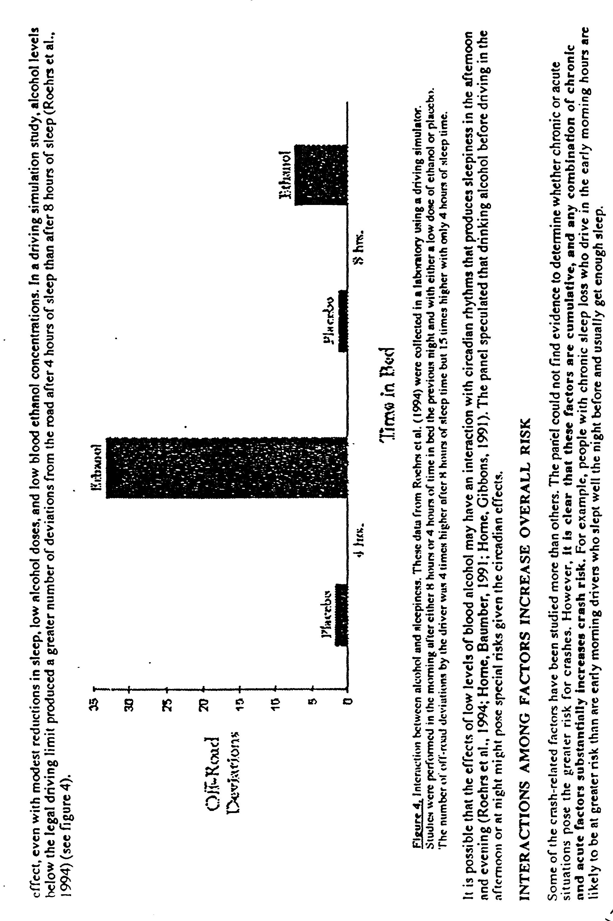
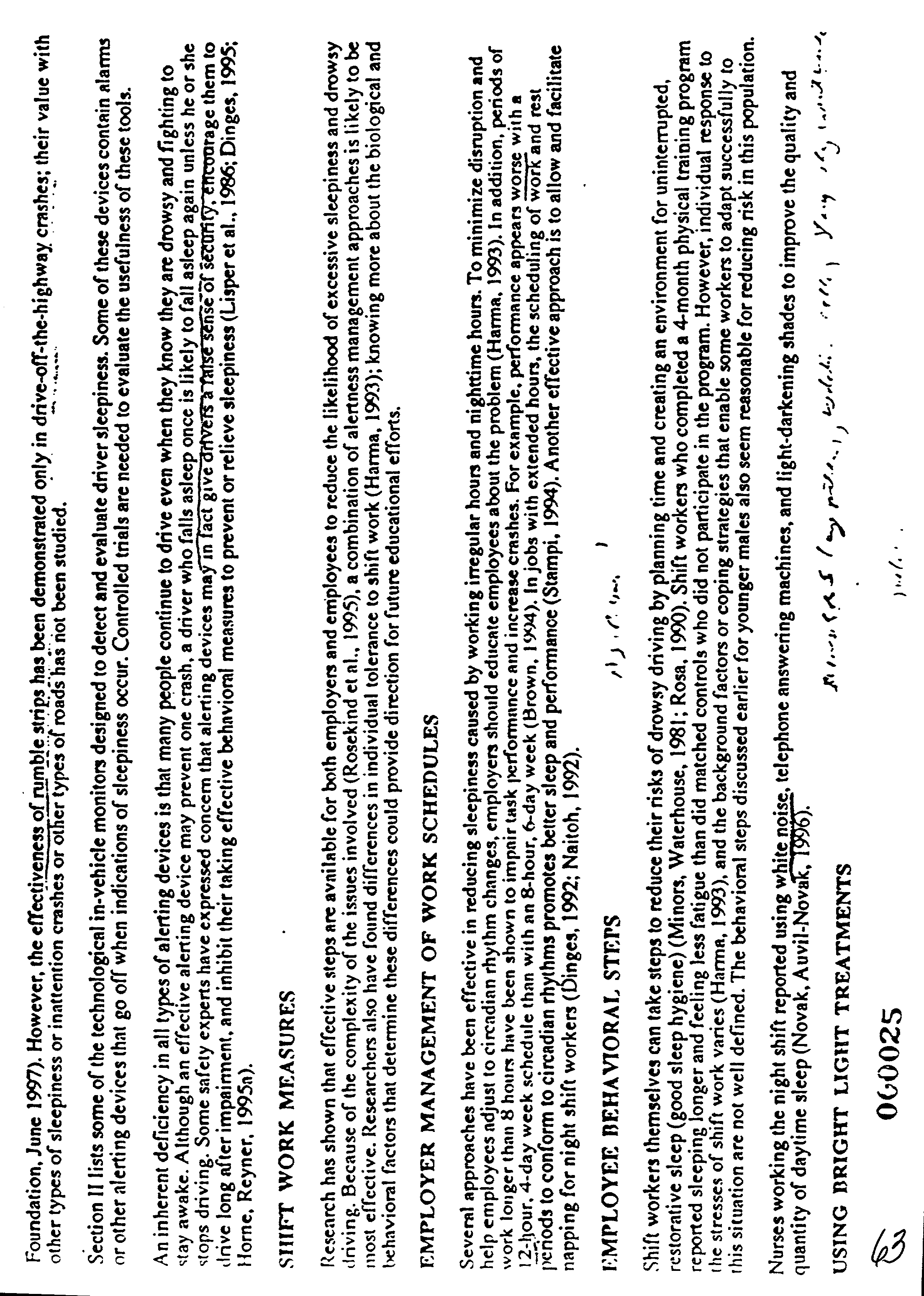
- As set forth in Appendix A, the National Highway Transportation Safety Administration (NHTSA) has addressed the issue of driver fatigue in a report regarding “Drowsy Driving and Automobile Crashes.” The enclosed report is incorporated herein by this reference thereto. Not only do long-haul truck drivers experience fatigue and drowsiness, but also drivers of other vehicles as well, with there being certain groups or categories of individuals being more susceptible to such risks than others.
- Because such sleepiness, drowsiness, and/or fatigue can lead to difficulties, and because technology may be available along the lines of those used in aircraft for recording events leading up to a vehicle failure or the like, it would be advantageous to provide a means by which both the driver can be alerted as to his/her drowsy condition in order to accommodate it, as well as a record of the events leading up to any crash or collision resulting from drowsiness. As set forth in more detail below, the present invention addresses these and other concerns.
- The present invention provides a vehicular monitoring system in the form of a black box or the like that uses signals generated from video input in order to determine the disposition of the vehicle on the roadway. By determining such vehicle disposition, the activity of the driver can then be monitored. In the event of a collision, crash, or if the vehicle drives off the road, the recording made by the vehicular black box of the present invention can then be used to evaluate and analyze the course of events preceding the crash or the like.
- Generally, two video cameras are used in order to determine the highway lane through which the vehicle is traveling (although it may be possible to use any number of cameras). For a solid line, a continuous signal is given. For a broken line, an intermittent signal is given. In conjunction with association with a turn signal, the present invention can evaluate the driver's performance in keeping the vehicle on the roadway and alert the driver when the vehicle is not properly disposed in its lane.
- Additionally, accuracy tests that indicate the mental, visual, and manual acuity of a driver are also disclosed herein and serve to provide an indication of future driving performance as generally the same skills needed to properly drive an automobile, a bus, a large truck or rig, or other motor vehicle as are needed to perform well on such tests.
- The system may be implemented for monitoring drivers associated with public safety concerns such as truck drivers and drivers with DUI records, sleep attack disorders and the like.
- It is an object of the present invention to provide a warning system for driver drowsiness and the like.
- It is yet another object of the present invention to provide a vehicular black box that allows reconstruction of an accident by providing a record of events prior to the occurrence of an accident.
- It is yet another object of the present invention to provide a combination driver-drowsiness system as well as a vehicular black box in order to promote better driving and fewer accidents on the highways.
- It is yet another object of the present invention to provide a system for rating a driver's performance based on a numeric scale characterizing a vehicle driver profile or signature based on his/her lane tracking ability.
- These and other objects and advantages of the present invention will be apparent from a review of the following specification and accompanying drawings.
- FIG. 1 is a general schematic depiction of the vehicular black box system of the present invention, showing a vehicle and driver travelling down a roadway towards the viewer.
- FIG. 2 is a front plan and schematic view of the vehicular black box system of the present invention showing the vehicle in the passing lane.
- FIG. 3 is a front left perspective view of the vehicular black box system of the present invention as attached to a large vehicle.
- FIG. 4 is a schematic representation of elements composing or comprising the vehicular black box of the present invention.
- FIG. 5 shows a schematic representation of a roadway accompanied with indicator signals that may be associated with the vehicular black box of the present invention.
- FIG. 6 shows a comparative depiction of curved and straight roadways for engagement by the vehicular black box of the present invention.
- FIG. 7 shows a schematic representation (scenario) of one vehicle passing another, implementing the present invention.
- FIG. 8 is a sectional view of a camera mounting within the housing of the side view mirror.
- FIGS. 9-12 are charts depicting signals arising from the detection of roadway markers, such as stripes or painted lines.
- FIG. 9 is a chart showing the regular and intermittent detection of dashed lines on a roadway.
- FIG. 10 is an enlargement of a portion of FIG. 9 showing contrast of reflected light.
- FIG. 11 is an enlargement of a portion of FIG. 9.
- FIG. 12 is an enlargement of a portion of FIG. 9.
- FIG. 13 is a depiction of a test and results used in the present invention, where an individual attempts to trace out a circle using a mouse or other device driving a cursor on a computer screen.
- FIG. 14 shows a depiction of a test to determine response time and accuracy, where the individual attempts to follow a spot on the screen with a mouse driving a cursor.
- FIG. 8 is a schematic diagram for an electronic circuit for the lane position status indicator of FIG. 5.
- The following appendices are incorporated herein by this reference thereto.
- Appendix A is a National Highway Transportation Safety Administration (NHTSA) Report.
- The detailed description set forth below in connection with the appended drawings is intended as a description of presently preferred embodiments of the invention and is not intended to represent the only forms in which the present invention may be constructed and/or utilized. The description sets forth the functions and the sequence of steps for constructing and operating the invention in connection with the illustrated embodiments. However, it is to be understood that the same or equivalent functions and sequences may be accomplished by different embodiments that are also intended to be encompassed within the spirit and scope of the invention.
- FIG. 1 shows a front plan view and perspective of a truck, rig, bus, or
other vehicle 100 incorporating the vehicular black box system of the present invention. As shown in FIG. 1, two cameras, 102, 104, are oppositely opposed on either side of the vehicle. Bothcameras cameras roadway 106 in order to detect the right shoulderwhite line 108 and the center dashedline 110. - The cameras may be mounted at any convenient location for looking down at the roadway, such as on the body of the vehicle or in the side view mirror attachments or housings, which are located on the doors or side of the vehicle. The cameras may be attached to the vehicle by any convenient means including bolting, welding, and adhesion.
- FIG. 8 illustrates one example of a camera mounting 800 within the housing of the
side view mirror 802. A mountingcylinder 804 is inserted through a hollowed out portion of thehousing 802 as shown in the figure. The camera 806 is bolted to the mounting cylinder, and likewise is inserted through a hollowed out portion of thehousing 802. The camera 806 is positioned to look downward at the road as indicated by the dashedarrow 808 preferably at an angle of approximately 45° with respect to the road. The vehicle itself, not shown in the figure, is located to the left of the housing. Additionally, thecross bar 810 shown in the figure is part of the mounting for the mirror. - Going back to FIG. 1, the camera, 102, on the right side of the vehicle seeks to detect the
line 108 on the right shoulder. Thecamera 104 on the left side of the vehicle seeks to detect the center dashedline 110. For a vehicles such as a truck, each camera is preferably at a distance of approximately 11 feet from the highway surface. - As shown in FIG. 1, the vehicle travels in the
right lane 111 of the four-lane highway divided in two lanes going in opposite directions. As set forth in more detail below, the black box of the present invention is not limited to use when the vehicle is travelling in the right highway lane. - Additionally, as shown in FIG. 1, the right shoulder
white line 108 may be illuminated by aright shoulder light 112 so that theright camera 102 may better pick up thewhite line 108 of the right shoulder. In one embodiment, the light, 112, may be a regular light focused upon the white line of the right shoulder, illuminating a circle of approximately 2 feet in diameter centered at the camera field. Additionally, the light 112 may be tuned to a special frequency of light (e.g. infrared) that might be available through a light source such as a laser, light emitting diode, or the like. A condensing lens may be used to spread out the image. Theright camera 102 may then pick up specifically reflected light by the right shoulder line 108 (of white or any other color) that is unique to the frequency of the laser light. In this way, other sources of illumination will be ignored, and the camera can focus specifically upon light reflected upon reflective or other material imbedded or incorporated into the paint of theright shoulder line 108. - The
camera 102 may be a CCD (Charge Coupled Device) that is extremely sensitive while being very small, preferably in the order of an inch and a half square and requiring very little power. Consequently, it is generally easy to fit cameras onto the vehicle such as an 18-wheel, big rig, or the like. Thecamera 102 is connected to a central control orrecording device 114 termed “black box.” - The left-
side camera 104, which is displaced horizontally on the other, or left side of the vehicle, functions similarly to theright side camera 102. A center dashedline light 116, may operate in a manner similar to that as theright side light 112 for thecamera 102. Theleft light 116 operates for theleft camera 104, while theright side light 112 operates for theright camera 102. The lights may be mounted at any convenient location for operating with the cameras. - Consequently, it can be seen that despite varying external conditions,
cameras - FIG. 2 shows a front schematic view of the
vehicle 100 of FIG. 1 when it is in the passinglane 118. When in the passing lane, the vehicle has a dashedwhite center line 110 on its right and a generally solid yellow lane line on its left. Theright camera 102 then picks up the dashed center line, while theleft camera 104 picks up the solid left shoulder line. - For travel in either a traveling lane, a passing lane, or a lane between (where the lines on both sides of the vehicle are dashed), the
right camera 102 and leftcamera 104 pick up the video signals from the lines (converting them to electrical signals) from which the travel of the vehicle in the lane can be determined. Any variance, drifting, swerving, or the like in the lane is detected by the cameras and recorded by the black box. By inspection of the signals from the cameras, the travel of the vehicle along the roadway can be determined. - FIG. 3 shows an alternative embodiment of the camera configuration of the present invention. The
left camera 104 is mounted along the side of thevehicle 100 so as to pick up the travel of the line on the left-hand side of the vehicle. In the case of FIG. 3, the illuminated lines picked up by the camera are the dashedcenter lines 302 as the vehicle is travelling in theright-most lane 304 of the roadway. - By detecting the presence and location of the highway lines on either side of a lane, the system can determine the magnitude of deviation of the vehicle from the center of the lane. Determination of the centroids of the signals received from the camera serves as an indication of the presence and relative position of the line. The magnitude of deviation from the center can be based on the detection of how far the vehicle is from the highway lines on each side of the vehicle. For a vehicle traveling exactly in the center of the lane, the distance between the vehicle and the highway lines on either side of the vehicle should be equal. Additionally, a driver may determine his ideal position in the lane and set the system to zero at that position, thereafter, any detected deviation away from the set position will be indicated to the driver. Alternatively, the system may detect and indicate to the driver any change from a previous position relative to the lane, without having a point of reference indicating an ideal position. An indication that the driver is constantly or erratically changing positions relative to the lane (say approximately every 2 seconds) may serve to indicate that the driver is weaving.
- Although two cameras have been illustrated in the above figures, any number of cameras may be used. For a system having one camera, the driver's position within a lane may be monitored by detecting the position of the highway line within the field of view of the camera by determining the centroids of the signals received. For a vehicle traveling in a straight path within a straight highway lane, the position of the highway line should be unchanging within the camera's field of view as described above. Any deviation from a given position indicates that the vehicle is swerving or otherwise not traveling in a straight line. Additionally, the driver may zero the system when he perceives his position in the lane to be the ideal position. Thereafter, the system would indicate any deviation from that position using one camera.
- In order to enhance the video pick up of the dashed lines, especially at nighttime, a source of illumination or the like may be used to shine light upon the roadway, particularly the area through which the dashed lines travel as the truck or vehicle travels along the roadway. Per the above, the camera may be tuned to receive light particular to the source of illumination so as to ensure the appropriate detection of the dashed lines as they travel past the vehicle. When the vehicle is in the left-most lane, the yellow continuous highway line may be picked up and detected by the camera.
- FIG. 4 shows one embodiment of the present invention, where camera signal inputs are fit into a self contained
black box 400, indicated by thearrow 401. Theblack box 400 includes aCK CPU 402 having a reset button 404. TheCK CPU 402 is associated with amemory element 405, particularly the RAM memory, which may be remotely interrogated, and executes program steps upon the data in order to derive centroids. The centroids may indicate that the vehicle is left in a position where it should be, appropriately centered, or right at the position where it should be in the lane (L C R in FIG. 4). The computer may be a commercial computer equipped with a fast (e.g. 30 HZ) frame grabber having software to compute road line profile centroid strings which are processed and analyzed to determine vehicle lane observance and to alert the driver if the vehicle is in danger of unintentionally departing the lane. - A traffic lane indicator (left, right) is shown in FIG. 4 and may be used in conjunction with the turn signal or the like to indicate the lane in which the black box currently “sees” the vehicle. Additionally, a delta or adjustment function may be provided so as to allow for adjustment of the black box, where for any reason, an adjustment needs to be made for indicating the center position in a lane. A reset button allows the system to reset to a default configuration.
- A display panel associated with the
black box 400 has a lane position status indicator, 406, shown towards the bottom of FIG. 4 as generally an analog indicator, allowing the driver to monitor the position of the vehicle as perceived by the black box. At the extreme left, an alert 408 is given to the driver to indicate that he is drifting too far left. The same is true at the opposite end of the status indicator, where an alert 410 is given when a driver drifts too far right. A center lane 412 or proper disposition indicator is shown in the center of the status indicator. Between the center lane indicator and the far left alert, a “drifting left” 414 indication is given. Similarly, a “drifting right” 416 alert is given when the vehicle is departing from the center and going towards the right. The drifting left and drifting right indications provide means by which the driver can be alerted to the status before an alert is given. The center lane, drifting left or drifting right indications may be displayed by lights which illuminate a portion of the display corresponding to the position of the vehicle within the lane. - FIG. 5 shows an alternative embodiment of a lane
position status indicator 500, showing a schematic view that disappears into the vanishing point of approximately 310 feet delivering approximately a seven degree (7°) angle for two lanes of a four-lane highway. - When the vehicle is centered in the lane, a
green light 502 goes on. Should it depart left or right (the area for which the green light shines, initially), a yellow light (504 or 506) comes on to alert the driver of his or her departure from the appropriate center line. After the yellow lights activate, a red light (508 or 510) come on, then pink (512 or 514), and then flashing red (516 or 518). All of these are shown in FIG. 5 and enable the black box of the present invention to provide not only a record of such departure from the center of the lane, but also an indication to the driver that such a departure is occurring. FIG. 15 is a schematic diagram for an electronic circuit for the laneposition status indicator 500. The elements of the circuit are labeled in the figure. - A sound alarm may accompany the flashing red light in order to alert the driver of his/her potentially hazardous driving. This will serve to awaken a driver who has fallen asleep at the wheel. Such alarm may be turned off by the push of a button or may automatically taper off as the vehicle position is corrected to the lane center. The alarm may further be activated by the push of a button to test if it is properly operating. Features which allow the driver to set the alarm volume and select a certain type of alarm sound may also be provided. An adjustable threshold may also be set by the driver to establish the level of centroid error to activate the audible alarm system.
- Before the alarm goes off, other milder warning signals, besides the light signals may be sounded such as a recorded voice warning when a driver is close to the flashing red zone. Various types of alarms and warning signals may be used, such as for example, the vibration of the wheel or seat, the activation of the vehicle air condition, heater, or fan, the automatic opening of the window, automatic activation of the radio, the release of a mist spray or perfume scent, or the sounding of a buzzer or car horn. Such alarm or warning signals may be scrambled so as to randomize agitation.
- Additionally, the alarm may be programmed to go off after a predetermined time period, say 20 seconds, in which the vehicle is detected as deviating from the lane center at a specified threshold value. Other possible indications for activating the alarm may be the absence of movement of the steering wheel for a specified time period (e.g. 20 seconds), erratic steering, detection that the car is on the rumble bars or road grooves on the left or right shoulders, or long term pattern of steering errors which may indicate that the driver is drowsy. Detection of the rumble bars on the road may also provide a back up warning system should the lane status indication system fail. The warning alarm system may also have a multiplicative feature such that multiple errors are weighted exponentially, rather then on an additive basis.
- The cameras and black box system may be on standby mode, and ready to operate once the vehicle is in forward gear. Furthermore, the black box may go into a high speed data logging mode when a dangerous situation is detected, to create a more accurate record of the driving in case an accident were to occur.
- The system may include other features such as a status button which allows the driver to bring up his record for review, or to display notes and messages sent from the company headquarters.
- FIG. 6 shows a vanishing point diagram for both
straight roads 600 andcurved roads 602. For curved roads, the radius of thecurvature 604 for asegment 606 of the road is determined by forming a circle having a curvature according to the portion of the segment as shown in the bottom of FIG. 6. The black box of the present invention helps to determine the centeredness of the vehicle, whether or not the vehicle is travelling on a straight road or a curved road by picking up centroids derived from the painted lines alongside the vehicle. - According to the present invention, a driver's overall performance based on the driver's lane tracking ability may be rated by monitoring and logging into the black box a driver's deviations from the center of a lane. The system may be set to record the instantaneous deviations from the center, and assign a numeric value to the deviation, which most conveniently is the distance away from the center. The average or RMS (root mean square) value of the deviations from the lane center monitored periodically (e.g. 30 times a second) on an ongoing basis, or over the course of a given trip could be used to assign a numeric value based on a scale for characterizing driver performance. Various methods for characterizing driver performance based on the driver's deviations from the center lane, recorded periodically for a given period of time, or based on other driving errors made, will be apparent to one skilled in the art.
- A black box according to the present invention, is preferably designed to be tamper proof, concealed, weatherproof, and to survive an accident. Additionally, stations for calibrating and interrogating the driver's back box may be provided, and frequent stops at such stations may be made mandatory for certain drivers, for example truck drivers and bus drivers. Such calibration stations may have a simulated road lane with the lines of the road laid down perfectly for allowing the driver to check the system as well as his own driving abilities to calibrate the system.
- FIG. 7 shows a diagram of a passing scenarios where a
first vehicle 700 passes a secondslower vehicle 702 on the left of that second slower vehicle. The positions of the passingvehicle 700 are indicated by the positions 1-5 in the figure, wherein thevehicle 700 starts fromposition 1 and finishes passing atposition 5. The left turn signal is turned on atposition - In one embodiment, the turn signals may indicate to the black box that a lane change is occurring, particularly when the speed of the vehicle stays the same or increases. Generally, vehicle speed is maintained or increased when passing a vehicle. However, very often the vehicle is slowed to a complete stop, or very nearly a complete stop, before engaging the turn signal for a left- or right-hand turn.
- FIGS. 9-12 show graphical output derived from data arising from the detection of the highway lines using a single camera.
- FIG. 9 is a plot of intensity versus time showing the intermittent, but regular, detection of the dashed lines present on the left-hand side of the travelling lane on a highway. The peaks indicate the amount of the line detected by the camera. The plot shows both the basic noise level as well as the market peaks indicating the detection of lines. Change of intensity in the peaks indicates that the driver has deviated from a straight path which is exactly parallel to the highway lines.
- FIGS. 10-12 show the intensity profiles of FIG. 9 in typical 3-D plots for fewer spots.
- Additionally, various test may be designed to characterize the driving profile of a driver, which include determining the driver's response time. Such tests may be given to drivers at interrogation stations or whenever else necessary to determine how well a driver can perform.
- A circle tracker test, shown in FIG. 13, is one example of an accuracy test that may be used to help determine the driver's activity behind the wheel. The circle tracker is a device that displays a circle 1300 on the monitor. The user taking the test is then required to trace the circle using the mouse.
Typical tracing lines 1302 are indicated in the figure. RMS error is recorded when the cursor departs from the circle on the screen. A log is kept with a running average of each error and can be used to show the manual coordination of an individual and his/her ability to accurately trace a circle on a computer screen. - Another test for characterizing a driver's response time and accuracy is a spot clicking test, shown in FIG. 14. A
spot 1400 moves about the screen through a random path, for example, as indicated by the dashed line in the figure, and the individual must place acircle 1402 over the spot using the cursor to navigate the circle. RMS error may be recorded as a function of the speed that the spot moves, and a running average may be kept of the error. Additionally, there are varying speeds which may be set for the moving spot, so that the ability of the driver to track the spot is well tested. - Alertness tests may also be administered while driving. Such tests might involve responding to a sound command or image projected on the windshield. For example, a screen windshield projection or virtual image may be activated in the driver's field of view on which a number, letter, word, symbol, or symbols are presented momentarily to the driver for identification; or a voice command might request the driver to recite a string of numbers. The driver may then be required to reply verbally to a voice deciphering device, squeeze a switch, interrupt a light beam or otherwise respond indicating his response time by so doing. His input may be logged and he could be informed of the ranking of his response. The screen information may be varied in size, color, orientation, length of projection time, etc., and will be programmed to appear when least expected.
- The above tests, including characterizing the driver's lane tracking abilities according to the present invention provide a way of projecting how likely a driver is to make a driving mistake which can lead to a fatal accident. Additionally, these tests can be used for field sobriety testing, as they are simple to administer.
- The monitoring of drivers can also be used for providing a safe system for drivers with sleep disorders characterized by the rapid onset of sleep called sleep attacks. Such drivers can be observed in a laboratory environment for determining and recording the driver's characteristic brain wave patterns during the transition from wakefulness to sleep. The driver's characteristic brain wave patterns can be stored into a device that monitors the driver's brain waves on the road and sounds an alarm when such pattern that can lead to a sleep attack is detected. A device for monitoring the driver's brain waves can be a band which may be a part of a variety of hats (i.e. cowboy, baseball, visor hats) containing conductive electrodes so placed as to sample the driver's EEG brain wave activity or change thereof. A suitable warning device, calibration system, recording element, and/or a tiny transmitter may be incorporated into the band.
- A number of alternative embodiments of the present invention may be achieved, aiding in the tracking, detection, auditing and/or monitoring of the vehicle's travel, particularly across the United States or otherwise.
- In one embodiment, a radar-like detection system may be used in order to maintain the distance between the vehicle in front of the driver's truck or other vehicle. This would allow the driver to maintain a safe distance between his vehicle and the one in front of him. In another embodiment, a light source of a specific frequency might be used to reflect off the vehicle in front, the time being gauged very accurately so as to determine the distance between the two vehicles. Other means may also be used. Generally, one second of time should exist between the vehicles for each ten (10) miles-per-hour of speed.
- With the development of wireless applications, information regarding the vehicle may be transmitted to a satellite uplink and then distributed to a central or Internet-based information distribution system. Devices such as those known as the Palm Pilot (marketed by 3Com) may be used to access the data and monitor the travel of the vehicle across the U.S. or otherwise. A panic button or the like may also be included in such wireless applications, immediately notifying authorities in case an event of highway piracy or vehicle breakdown should occur.
- GPS applications may also be used, such that the satellite uplink information includes information derived from the Global Positioning System (GPS). Geographical information in the form of longitude and latitude are then delivered with the satellite uplink information. Additionally, information regarding the status of the vehicle according to its disposition and its lane of travel can also be uploaded, as well as a history of any alerts that may have occurred. With respect to the latter, the association of the turn signal with the black box becomes a significant feature as such alerts would be generated without the coupling of the turn signal to the black box.
- Additionally, automatic log book applications could be coordinated with the black box of the present invention in order to provide automatic logging of the travel, expenses, and other relevant data with respect to the operation, maintenance, and mileage of the vehicle.
- As forecasted by some, JavaScript applications or the like can be used with respect to all mechanical items on the vehicle. For example, when the oil reaches the end of its useful life, a signal can be given that the oil should be changed. Additionally, headlights that are about to go out or that have been used passed 90% of their useful life can also give signals that they are ready to be replaced, and the same can then be transmitted automatically for the next scheduled maintenance stop for the vehicle.
- By providing a travel-detection and maintenance system along the lines described above, greater safety is provided for both the driver and those travelling along the same roads as the vehicle. This may allow for greater cargo capacities to be allowed on the highways, as wireless and other monitoring of the vehicle provide a greater margin of safety, possibly far exceeding that necessary for safe operation.
- While the present invention has been described with regards to particular embodiments, it is recognized that additional variations of the present invention may be devised without departing from the inventive concept.


Claims (50)
1. A monitor for a vehicle allowing oversight and detection of vehicular activity, comprising:
a first camera, said first camera directed towards a roadway upon which the vehicle is traveling, said first camera directed towards a first line painted on said roadway; and
a roadway detector, said roadway detector coupled to said first camera and receiving signals from said first camera, said roadway detector detecting signals from said first camera indicating presence of said first line.
2. The monitor of claim 1 , further comprising:
a recorder, said recorder coupled to said first camera and recording signals transmitted by said camera; whereby
activity of the vehicle on said roadway is detected and recorded for present and future review and analysis.
3. The monitor of claim 2 , further comprising:
said recorder being capable of preserving said camera signals despite a collision, accident, or similar catastrophe.
4. The monitor of claim 2 , further comprising:
an indicator, said indicator coupled to said roadway detector, said indicator indicating disposition of said vehicle upon said roadway relative to said first line.
5. The monitor of claim 4 wherein said indicator indicates deviation of the vehicle from a fixed distance relative to said first line.
6. The monitor of claim 5 wherein said fixed distance is set by the driver.
7. The monitor of claim 4 wherein said indicator indicates change in position from a previous position relative to said first line.
8. The monitor of claim 7 wherein said indicator indicates that the driver is weaving when constant change in position is detected.
9. The monitor of claim 5 , further comprising:
said indicator issuing a warning when the vehicle departs from a path defined by said first line.
10. The monitor of claim 9 wherein said warning is selected from a group comprising light, sound, vibration, mist, wind, heat, cold air, scent, or a combination thereof.
11. The monitor of claim 9 wherein the driver of the vehicle may set a threshold value for the amount that the vehicle departs from said path for said indicator to issue said warning.
12. The monitor of claim 9 wherein said warning is issued when either the vehicle departs from a position having a fixed distance from said first line, when the vehicle constantly changes its position from a previous position relative to said line, when a long term pattern of steering errors is detected, when long term non-movement of the vehicle's steering wheel is detected, when the vehicle's traveling on the rumble bars of said roadway is detected, or a combination thereof.
13. The monitor of claim 2 , further comprising:
a second camera, said second camera directed towards said roadway and directed towards a second line painted on said roadway; said first line being on one side of the vehicle and said second line being on an opposite side of said vehicle, said vehicle travelling between said first and second lines;
said second camera coupled to said roadway detector, said roadway detector receiving signals from said second camera and detecting signals from said second camera indicating presence of said second line; whereby
coordinated detection of said first and second lines by said roadway detector indicates disposition of the vehicle between said first and second lines and proper travel of the vehicle along said roadway between said first and second lines.
14. The monitor of claim 13 , further comprising:
an indicator, said indicator coupled to said roadway detector, said indicator indicating disposition of said vehicle upon said roadway relative to said first and second lines.
15. The monitor of claim 14 wherein said indicator indicates deviations of the vehicle from a center position between said first and second lines.
16. The monitor of claim 14 , further comprising:
said indicator issuing a warning when the vehicle departs from a path defined by said first and second lines.
17. The monitor of claim 2 , further comprising:
a light source, said light source illuminating said roadway before said first camera; whereby
said roadway, including said first line, are better detected by said first camera.
18. The monitor of claim 17 , further comprising:
said light source transmitting light of a certain character;
said first camera detecting light of said certain character; whereby
said light source may selectively illuminate said roadway for said first camera by light of said certain character and allowing said first camera to specifically concentrate on said light of certain character and ignore light not having said certain character.
19. The monitor of claim 18 wherein said certain character of light is infrared.
20. The monitor of claim 2 , further comprising:
said roadway detector determining centroids of signals received from said first camera, said centroids indicating presence and relative location of said first line.
21. The monitor of claim 2 , further comprising:
said roadway detector coupled to a turn indicator, said roadway detector compensating for departure of said vehicle from a path associated with said first line.
22. The monitor of claim 2 , further comprising:
a vehicle distance detector, said vehicle distance detector coupled to said roadway detector, said vehicle distance detector detecting a distance between the vehicle and a second vehicle in front of the vehicle, said vehicle distance detector indicating said distance.
23. The monitor of claim 22 , further comprising:
a cruise control, said cruise control coupled to a throttle of said vehicle and said vehicle distance detector, said cruise control keeping or holding the vehicle at a certain minimum distance from said second vehicle.
24. The monitor of claim 2 , further comprising:
a wireless communication system, said wireless communication system coupled to said roadway detector, said wireless communication system providing wireless communications between the monitor and a wireless communications network.
25. The monitor of claim 24 , further comprising:
a global positioning system (GPS) receiver, said GPS receiver coupled to said wireless communication system; whereby
vehicle location information may be transmitted to said wireless communications network.
26. The monitor of claim 24 , further comprising:
a logbook recorder, said logbook recorder coupled to said wireless communication network, said logbook recorder recording data pertinent to operation and maintenance of said vehicle, whereby
remote monitoring of the vehicle and its operational status may occur when data recorded in said logbook is transmitted to said wireless communications network and received by another.
27. The monitor of claim 2 wherein said first camera is mounted within a side mirror housing.
28. The monitor of claim 2 wherein the driver may zero the system to indicate a set position where the driver desires to be relative to said first line, and wherein said detector detects deviations from said set position.
29. The monitor of claim 2 wherein said detector detects change from a previous position relative to said first line.
30. The monitor of claim 2 wherein said detector detects non-movement of the steering wheel of said vehicle.
31. The monitor of claim 2 whereby when the driver activates the turn signal of said vehicle, said detector detects and associates said vehicle's speed and position with the driver's changing of a traffic lane.
32. A monitor for a vehicle allowing oversight, detection, and recording of vehicular activity, comprising:
a first camera, said first camera directed towards a roadway upon which the vehicle is travelling, said first camera directed towards a first line painted on said roadway;
a second camera, said second camera directed towards said roadway and directed towards a second line painted on said roadway; said first line being on one side of the vehicle and said second line being on an opposite side of said vehicle, said vehicle travelling between said first and second lines;
first and second light sources, said first and second light sources respectively illuminating said roadway before said first and second cameras so that said roadway, including said first and second lines, are better detected by, respectively, said first and second cameras;
a roadway detector, said roadway detector coupled to said first and second cameras and receiving signals from said first and second cameras, said roadway detector detecting signals from said first camera indicating presence of said first line, said roadway detector detecting signals from said second camera indicating presence of said second line, so that coordinated detection of said first and second lines by said roadway detector indicates disposition of the vehicle between said first and second lines and proper travel of the vehicle along said roadway between said first and second lines;
said roadway detector determining centroids of signals received from said first and second cameras, said centroids respectively indicating presence and relative location of said first and second lines;
said roadway detector coupled to a turn indicator, said roadway detector compensating for departure of said vehicle from a path associated with said first and second lines when said turn indicator is activated;
an indicator, said indicator coupled to said roadway detector, said indicator indicating disposition of said vehicle upon said roadway relative to said first and second lines, said indicator issuing a warning when the vehicle departs from a path defined by said first and second lines; and
a recorder, said recorder coupled to said first and second cameras and recording signals transmitted by said cameras, said recorder preserving said camera signals despite a collision, accident, or similar catastrophe; whereby
activity of the vehicle on said roadway is detected to aid a driver of the vehicle and recorded for future review and analysis.
33. The monitor of claim 32 , further comprising:
said first and second light sources transmitting light of a certain character;
said first and second cameras detecting light of said certain character; whereby
said light source may selectively illuminate said roadway for said first and second cameras by light of said certain character and allowing said first and second cameras to specifically concentrate on said light of certain character and ignore light not having said certain character.
34. The monitor of claim 32 , further comprising:
a vehicle distance detector, said vehicle distance detector coupled to said roadway detector, said vehicle distance detector detecting a distance between the vehicle and a second vehicle in front of the vehicle, said vehicle distance detector indicating said distance.
35. The monitor of claim 34 , further comprising:
a cruise control, said cruise control coupled to a throttle of said vehicle and said vehicle distance detector, said cruise control keeping or holding the vehicle at a certain minimum distance from said second vehicle.
36. The monitor of claim 32 , further comprising:
a wireless communication system, said wireless communication system coupled to said roadway detector, said wireless communication system providing wireless communications between the monitor and a wireless communications network.
37. The monitor of claim 36 , further comprising:
a global positioning system (GPS) receiver, said GPS receiver coupled to said wireless communication system; whereby
vehicle location information may be transmitted to said wireless communications network.
38. The monitor of claim 37 , further comprising:
a logbook recorder, said logbook recorder coupled to said wireless communication network, said logbook recorder recording data pertinent to operation and maintenance of said vehicle, whereby
remote monitoring of the vehicle and its operational status may occur when data recorded in said logbook is transmitted to said wireless communications network and received by another.
39. A method for testing potential driver ability, the steps comprising:
providing a circle;
tracing said circle, said circle traced by a driver; and
detecting departure from said circle by said tracing; whereby
manual dexterity and/or eye/hand coordination is indicated by said detection of departure of said tracing from said circle.
40. A method for testing potential driver ability, the steps comprising:
providing a moving target;
tracking said moving target, said tracking performed by a driver; and
detecting accuracy and speed of said tracking of said moving target; whereby
speed and accuracy of said tracking are determined by said detecting.
41. A method for rating and/or monitoring a driver's performance comprising:
providing a monitor for a vehicle allowing oversight, detection, and recording of vehicular activity, said monitor comprising:
a first camera, said first camera directed towards a roadway upon which the vehicle is traveling, said first camera directed towards a first line painted on said roadway;
a roadway detector, said roadway detector coupled to said first camera and receiving signals from said first camera, said roadway detector detecting signals from said first camera indicating presence of said first line, and
a recorder, said recorder coupled to said first camera and recording signals transmitted by said camera, said recorder preserving said camera signals; and
detecting and recording activity of the vehicle on said roadway for present and future review and analysis.
42. The method of claim 41 wherein said detector detects driver deviations from a path relative to said first line.
43. The method of claim 42 further comprising rating driver performance based on a record of accumulated deviations recorded over a time period.
44. The method of claim 43 wherein said driver performance is rated by determining the root mean square value of said accumulated deviations.
45. The method of claim 43 wherein said path is defined by a line having a set distance away from said first line.
46. The method of claim 43 further comprising:
said monitor further having a second camera, said second camera directed towards said roadway and directed towards a second line painted on said roadway;
said first line being on one side of the vehicle and said second line being on an opposite side of said vehicle, said vehicle traveling between said first and second lines;
said second camera coupled to said roadway detector, said roadway detector receiving signals from said second camera and detecting signals from said second camera indicating presence of said second line; whereby
coordinated detection of said first and second lines by said roadway detector indicates disposition of the vehicle between said first and second lines and proper travel of the vehicle along said roadway between said first and second lines; and
said path being a center path between said first and second lines.
47. The method of claim 41 further comprising providing a station having a simulated road lane for calibrating the monitor, and testing the driver.
48. A method for testing a driver's performance comprising:
providing a random sound command, image projection, or a combination of both;
responding to said image, said responding performed by the driver; and
determining the speed and accuracy of said responding.
49. The method of claim 48 wherein said sound command and image projection are provided while the driver is driving, said image projection being projected on the windshield of the vehicle wherein
alertness of the driver is determined by the speed and accuracy of said responding.
50. A method of monitoring a driver comprising:
recording the driver's brain wave patterns;
determining the character of said patterns when the driver is drowsy or falling asleep;
monitoring the driver's brain waves while driving;
comparing said patterns when the driver is drowsy or falling asleep to the brain waves while driving; and
determining when the driver is drowsy or falling asleep based on said comparing.
Priority Applications (2)
| Application Number | Priority Date | Filing Date | Title |
|---|---|---|---|
| US09/991,509 US6894606B2 (en) | 2000-11-22 | 2001-11-21 | Vehicular black box monitoring system |
| US11/004,491 US20050099279A1 (en) | 2000-11-22 | 2004-12-02 | Vehicular black box monitoring system |
Applications Claiming Priority (2)
| Application Number | Priority Date | Filing Date | Title |
|---|---|---|---|
| US25253700P | 2000-11-22 | 2000-11-22 | |
| US09/991,509 US6894606B2 (en) | 2000-11-22 | 2001-11-21 | Vehicular black box monitoring system |
Related Child Applications (1)
| Application Number | Title | Priority Date | Filing Date |
|---|---|---|---|
| US11/004,491 Division US20050099279A1 (en) | 2000-11-22 | 2004-12-02 | Vehicular black box monitoring system |
Publications (2)
| Publication Number | Publication Date |
|---|---|
| US20020105438A1 true US20020105438A1 (en) | 2002-08-08 |
| US6894606B2 US6894606B2 (en) | 2005-05-17 |
Family
ID=26942401
Family Applications (2)
| Application Number | Title | Priority Date | Filing Date |
|---|---|---|---|
| US09/991,509 Expired - Fee Related US6894606B2 (en) | 2000-11-22 | 2001-11-21 | Vehicular black box monitoring system |
| US11/004,491 Abandoned US20050099279A1 (en) | 2000-11-22 | 2004-12-02 | Vehicular black box monitoring system |
Family Applications After (1)
| Application Number | Title | Priority Date | Filing Date |
|---|---|---|---|
| US11/004,491 Abandoned US20050099279A1 (en) | 2000-11-22 | 2004-12-02 | Vehicular black box monitoring system |
Country Status (1)
| Country | Link |
|---|---|
| US (2) | US6894606B2 (en) |
Cited By (60)
| Publication number | Priority date | Publication date | Assignee | Title |
|---|---|---|---|---|
| US20030023614A1 (en) * | 2001-07-18 | 2003-01-30 | Newstrom Bryan J. | Populating geospatial database for onboard intelligent vehicle applications |
| US20030128182A1 (en) * | 2001-10-01 | 2003-07-10 | Max Donath | Virtual mirror |
| US20030154009A1 (en) * | 2002-01-25 | 2003-08-14 | Basir Otman A. | Vehicle visual and non-visual data recording system |
| US20040011120A1 (en) * | 2001-03-08 | 2004-01-22 | Jean-Christophe Riat | Device for detecting a running surface and vehicle using same |
| US20040143381A1 (en) * | 2002-11-05 | 2004-07-22 | Uwe Regensburger | Switching a turn signal indicator on or off |
| US6795759B2 (en) * | 2002-08-26 | 2004-09-21 | International Business Machines Corporation | Secure logging of vehicle data |
| US20050275520A1 (en) * | 2004-06-09 | 2005-12-15 | Nissan Motor Co., Ltd. | Driver assisting system for vehicle and vehicle equipped with the driver assisting system |
| US20060020452A1 (en) * | 2004-07-26 | 2006-01-26 | Yoshiharu Yamamoto | Noise generation apparatus |
| US7012509B2 (en) | 2001-03-08 | 2006-03-14 | Peugeot Citroen Automobiles Sa | Device for detecting a running surface for vehicle and vehicle using same |
| US20060132601A1 (en) * | 2004-12-07 | 2006-06-22 | Kabushiki Kaisha Honda Lock | Vehicular visual assistance system |
| EP1788468A2 (en) * | 2005-11-21 | 2007-05-23 | Robert Bosch Gmbh | System for warning the driver of a motor vehicle |
| US20080013324A1 (en) * | 2005-07-26 | 2008-01-17 | Yu Jing J | Integrated led bulb |
| US20080143234A1 (en) * | 2006-02-09 | 2008-06-19 | Jing Jing Yu | Substantially inseparable led lamp assembly |
| US20090021951A1 (en) * | 2007-07-13 | 2009-01-22 | Jing Jing Yu | Watertight led lamp |
| US20090222163A1 (en) * | 2005-12-08 | 2009-09-03 | Smart Drive Systems, Inc. | Memory Management In Event Recording Systems |
| US7716002B1 (en) * | 2002-06-11 | 2010-05-11 | Injury Sciences Llc | Methods and apparatus for using black box data to analyze vehicular accidents |
| US20100129263A1 (en) * | 2006-07-04 | 2010-05-27 | Toshiya Arakawa | Method for Supporting A Driver Using Fragrance Emissions |
| US20100264806A1 (en) * | 2009-04-20 | 2010-10-21 | Beijing Yu | Led light bulbs in pyramidal structure for efficient heat dissipation |
| US7850362B2 (en) | 2004-11-10 | 2010-12-14 | 1 Energy Solutions, Inc. | Removable LED lamp holder with socket |
| US7850361B2 (en) | 2004-11-10 | 2010-12-14 | 1 Energy Solutions, Inc. | Removable LED lamp holder |
| US20110029195A1 (en) * | 2007-08-06 | 2011-02-03 | Toyota Jidosha Kabushiki Kaisha | Drive assistance device |
| US7883261B2 (en) | 2008-04-08 | 2011-02-08 | 1 Energy Solutions, Inc. | Water-resistant and replaceable LED lamps |
| US20110153266A1 (en) * | 2009-12-23 | 2011-06-23 | Regents Of The University Of Minnesota | Augmented vehicle location system |
| US8016440B2 (en) | 2005-02-14 | 2011-09-13 | 1 Energy Solutions, Inc. | Interchangeable LED bulbs |
| US20120154156A1 (en) * | 2009-08-26 | 2012-06-21 | Venska Utvecklings Entreprenoren Susen Ab | Method for wakening up a driver of a motor vehicle |
| US8314564B2 (en) | 2008-11-04 | 2012-11-20 | 1 Energy Solutions, Inc. | Capacitive full-wave circuit for LED light strings |
| WO2013023032A1 (en) * | 2011-08-11 | 2013-02-14 | Ford Global Technologies, Llc | System and method for establishing acoustic metrics to detect driver impairment |
| US8376606B2 (en) | 2008-04-08 | 2013-02-19 | 1 Energy Solutions, Inc. | Water resistant and replaceable LED lamps for light strings |
| US20130170107A1 (en) * | 2012-01-04 | 2013-07-04 | Doug Dean | Enclosure for Preventing Tampering of Mobile Communication Equipment in Transportation Industry |
| US20130252638A1 (en) * | 2011-10-21 | 2013-09-26 | Alohar Mobile Inc. | Real-Time Determination of User Stays of a Mobile Device |
| US8595034B2 (en) | 1996-01-29 | 2013-11-26 | Progressive Casualty Insurance Company | Monitoring system for determining and communicating a cost of insurance |
| GB2511612A (en) * | 2013-02-13 | 2014-09-10 | Wdm Ltd | Apparatus and method for detecting vehicle weave |
| US8836224B2 (en) | 2009-08-26 | 2014-09-16 | 1 Energy Solutions, Inc. | Compact converter plug for LED light strings |
| US8868288B2 (en) | 2006-11-09 | 2014-10-21 | Smartdrive Systems, Inc. | Vehicle exception event management systems |
| US8892451B2 (en) | 1996-01-29 | 2014-11-18 | Progressive Casualty Insurance Company | Vehicle monitoring system |
| US8892310B1 (en) | 2014-02-21 | 2014-11-18 | Smartdrive Systems, Inc. | System and method to detect execution of driving maneuvers |
| US8989959B2 (en) | 2006-11-07 | 2015-03-24 | Smartdrive Systems, Inc. | Vehicle operator performance history recording, scoring and reporting systems |
| CN104581090A (en) * | 2015-02-11 | 2015-04-29 | 宁波澎湃电子科技有限公司 | Beforehand security and protection system and monitoring method |
| CN104601967A (en) * | 2015-02-11 | 2015-05-06 | 宁波澎湃电子科技有限公司 | Beforehand security and protection system and monitoring method |
| US20150248132A1 (en) * | 2014-02-28 | 2015-09-03 | GM Global Technology Operations LLC | Jerk reduction in transition between lane-centering and lane-keeping steering systems |
| US9183679B2 (en) | 2007-05-08 | 2015-11-10 | Smartdrive Systems, Inc. | Distributed vehicle event recorder systems having a portable memory data transfer system |
| US9201842B2 (en) | 2006-03-16 | 2015-12-01 | Smartdrive Systems, Inc. | Vehicle event recorder systems and networks having integrated cellular wireless communications systems |
| US9402060B2 (en) | 2006-03-16 | 2016-07-26 | Smartdrive Systems, Inc. | Vehicle event recorders with integrated web server |
| US9501878B2 (en) | 2013-10-16 | 2016-11-22 | Smartdrive Systems, Inc. | Vehicle event playback apparatus and methods |
| US9554080B2 (en) | 2006-11-07 | 2017-01-24 | Smartdrive Systems, Inc. | Power management systems for automotive video event recorders |
| DE102015219402A1 (en) | 2015-09-25 | 2017-03-30 | Continental Automotive Gmbh | Method for operating an occupant protection system and corresponding control device and motor vehicle |
| US9610955B2 (en) | 2013-11-11 | 2017-04-04 | Smartdrive Systems, Inc. | Vehicle fuel consumption monitor and feedback systems |
| US9633318B2 (en) | 2005-12-08 | 2017-04-25 | Smartdrive Systems, Inc. | Vehicle event recorder systems |
| US9663127B2 (en) | 2014-10-28 | 2017-05-30 | Smartdrive Systems, Inc. | Rail vehicle event detection and recording system |
| US9728228B2 (en) | 2012-08-10 | 2017-08-08 | Smartdrive Systems, Inc. | Vehicle event playback apparatus and methods |
| WO2019047803A1 (en) * | 2017-09-06 | 2019-03-14 | 李公健 | Vehicle stopping system for identifying angular distance of vehicle parking to tactile paving path and road shoulder |
| US10275666B2 (en) * | 2016-03-24 | 2019-04-30 | Nissan Motor Co., Ltd. | Travel lane detection method and travel lane detection device |
| US20200172004A1 (en) * | 2004-03-15 | 2020-06-04 | Anita Au | Camera systems for vehicles |
| US10930093B2 (en) | 2015-04-01 | 2021-02-23 | Smartdrive Systems, Inc. | Vehicle event recording system and method |
| US11030702B1 (en) | 2012-02-02 | 2021-06-08 | Progressive Casualty Insurance Company | Mobile insurance platform system |
| US11069257B2 (en) | 2014-11-13 | 2021-07-20 | Smartdrive Systems, Inc. | System and method for detecting a vehicle event and generating review criteria |
| US11373502B2 (en) * | 2018-01-31 | 2022-06-28 | Denso Corporation | Vehicle alert apparatus |
| US11377094B2 (en) * | 2011-02-18 | 2022-07-05 | Honda Motor Co., Ltd. | System and method for responding to driver behavior |
| US11383721B2 (en) | 2013-03-15 | 2022-07-12 | Honda Motor Co., Ltd. | System and method for responding to driver state |
| US11549815B2 (en) | 2019-06-28 | 2023-01-10 | GM Cruise Holdings LLC. | Map change detection |
Families Citing this family (64)
| Publication number | Priority date | Publication date | Assignee | Title |
|---|---|---|---|---|
| DE60028907T2 (en) | 1999-11-24 | 2007-02-15 | Donnelly Corp., Holland | Rearview mirror with utility function |
| GB0108766D0 (en) * | 2001-04-06 | 2001-05-30 | Ricardo Consulting Engineers 1 | Driveability rating method and system |
| US7382236B2 (en) * | 2002-06-11 | 2008-06-03 | Robert Bosch Gmbh | Method and device for driver information and to react to leaving the lane |
| JP3922194B2 (en) * | 2003-03-11 | 2007-05-30 | 日産自動車株式会社 | Lane departure warning device |
| US6931309B2 (en) * | 2003-05-06 | 2005-08-16 | Innosurance, Inc. | Motor vehicle operating data collection and analysis |
| JP4062172B2 (en) * | 2003-05-28 | 2008-03-19 | 日産自動車株式会社 | VEHICLE ALARM DEVICE AND lane departure prevention device equipped with the same |
| US20050015122A1 (en) * | 2003-06-03 | 2005-01-20 | Mott Christopher Grey | System and method for control of a subject's circadian cycle |
| DE10350779A1 (en) * | 2003-10-30 | 2005-06-02 | Robert Bosch Gmbh | Lane keeping system for a motor vehicle and operating method |
| JP2005173929A (en) * | 2003-12-10 | 2005-06-30 | Denso Corp | Device for determining awakening degree |
| US10664115B2 (en) * | 2004-01-09 | 2020-05-26 | Donnelly Corporation | Vehicular vision system with head up display |
| DE102004028763A1 (en) * | 2004-06-16 | 2006-01-19 | Daimlerchrysler Ag | Andockassistent |
| US20060095172A1 (en) * | 2004-10-28 | 2006-05-04 | Abramovitch Daniel Y | Optical navigation system for vehicles |
| EP1851076B1 (en) * | 2005-02-14 | 2008-12-03 | Koninklijke Philips Electronics N.V. | Vehicle accessories for enhancing smells |
| US20060212195A1 (en) * | 2005-03-15 | 2006-09-21 | Veith Gregory W | Vehicle data recorder and telematic device |
| US9189895B2 (en) | 2005-06-01 | 2015-11-17 | Allstate Insurance Company | Motor vehicle operating data collection and analysis |
| US7117075B1 (en) | 2005-08-15 | 2006-10-03 | Report On Board Llc | Driver activity and vehicle operation logging and reporting |
| US9818120B2 (en) | 2015-02-20 | 2017-11-14 | Innovative Global Systems, Llc | Automated at-the-pump system and method for managing vehicle fuel purchases |
| US8626377B2 (en) | 2005-08-15 | 2014-01-07 | Innovative Global Systems, Llc | Method for data communication between a vehicle and fuel pump |
| US9067565B2 (en) * | 2006-05-22 | 2015-06-30 | Inthinc Technology Solutions, Inc. | System and method for evaluating driver behavior |
| US7859392B2 (en) | 2006-05-22 | 2010-12-28 | Iwi, Inc. | System and method for monitoring and updating speed-by-street data |
| US7602132B2 (en) * | 2006-09-27 | 2009-10-13 | Rockwell Automation Technologies, Inc. | Methods and system for motor drive information capture |
| US7652583B2 (en) * | 2007-03-20 | 2010-01-26 | Deere & Company | Method and system for maintaining operator alertness |
| WO2008144908A1 (en) * | 2007-05-29 | 2008-12-04 | Christopher Mott | Methods and systems for circadian physiology predictions |
| US8825277B2 (en) * | 2007-06-05 | 2014-09-02 | Inthinc Technology Solutions, Inc. | System and method for the collection, correlation and use of vehicle collision data |
| US20080316312A1 (en) * | 2007-06-21 | 2008-12-25 | Francisco Castillo | System for capturing video of an accident upon detecting a potential impact event |
| US8666590B2 (en) | 2007-06-22 | 2014-03-04 | Inthinc Technology Solutions, Inc. | System and method for naming, filtering, and recall of remotely monitored event data |
| US9129460B2 (en) | 2007-06-25 | 2015-09-08 | Inthinc Technology Solutions, Inc. | System and method for monitoring and improving driver behavior |
| US7999670B2 (en) | 2007-07-02 | 2011-08-16 | Inthinc Technology Solutions, Inc. | System and method for defining areas of interest and modifying asset monitoring in relation thereto |
| US8577703B2 (en) | 2007-07-17 | 2013-11-05 | Inthinc Technology Solutions, Inc. | System and method for categorizing driving behavior using driver mentoring and/or monitoring equipment to determine an underwriting risk |
| US8818618B2 (en) | 2007-07-17 | 2014-08-26 | Inthinc Technology Solutions, Inc. | System and method for providing a user interface for vehicle monitoring system users and insurers |
| US9117246B2 (en) * | 2007-07-17 | 2015-08-25 | Inthinc Technology Solutions, Inc. | System and method for providing a user interface for vehicle mentoring system users and insurers |
| US20090051510A1 (en) * | 2007-08-21 | 2009-02-26 | Todd Follmer | System and Method for Detecting and Reporting Vehicle Damage |
| US7876205B2 (en) | 2007-10-02 | 2011-01-25 | Inthinc Technology Solutions, Inc. | System and method for detecting use of a wireless device in a moving vehicle |
| KR20090040622A (en) * | 2007-10-22 | 2009-04-27 | 한국전자통신연구원 | Method and apparatus for providing vehicle accident information |
| WO2009052633A1 (en) | 2007-10-25 | 2009-04-30 | Christopher Mott | Systems and methods for individualized alertness predictions |
| WO2009058914A1 (en) * | 2007-10-30 | 2009-05-07 | Webster Allen E | Vehicle safety camera system |
| US7868770B2 (en) * | 2007-11-14 | 2011-01-11 | Al-Mutairi Sami H | Warning device for drivers and the like |
| US7800348B2 (en) * | 2007-11-21 | 2010-09-21 | Rockwell Automation Technologies, Inc. | Motor drive with VAR compensation |
| KR101351656B1 (en) * | 2012-03-30 | 2014-01-16 | 대성전기공업 주식회사 | Vehicular glance lighting apparatus |
| US9201504B2 (en) * | 2007-11-29 | 2015-12-01 | Daesung Electric Co., Ltd. | Vehicular glance lighting apparatus and a method for controlling the same |
| JP2009217682A (en) * | 2008-03-12 | 2009-09-24 | Yazaki Corp | Display for vehicle |
| US7786850B1 (en) | 2008-06-16 | 2010-08-31 | Gianni Arcaini | Method and apparatus for bridge collision alert monitoring and impact analysis |
| US8688180B2 (en) | 2008-08-06 | 2014-04-01 | Inthinc Technology Solutions, Inc. | System and method for detecting use of a wireless device while driving |
| CA2649731C (en) * | 2008-11-05 | 2015-07-21 | The George Washington University | An unobtrusive driver drowsiness detection method |
| US20100131300A1 (en) | 2008-11-26 | 2010-05-27 | Fred Collopy | Visible insurance |
| JP4862898B2 (en) * | 2009-01-09 | 2012-01-25 | 株式会社デンソー | Vehicle alarm generator |
| US8963702B2 (en) | 2009-02-13 | 2015-02-24 | Inthinc Technology Solutions, Inc. | System and method for viewing and correcting data in a street mapping database |
| US8892341B2 (en) | 2009-02-13 | 2014-11-18 | Inthinc Technology Solutions, Inc. | Driver mentoring to improve vehicle operation |
| EP2420985B1 (en) * | 2009-04-15 | 2016-11-09 | Toyota Jidosha Kabushiki Kaisha | Alarm output control apparatus |
| US8794976B2 (en) * | 2009-05-07 | 2014-08-05 | Trustees Of The Univ. Of Pennsylvania | Systems and methods for evaluating neurobehavioural performance from reaction time tests |
| US8521439B2 (en) * | 2009-05-08 | 2013-08-27 | Pulsar Informatics, Inc. | Method of using a calibration system to generate a latency value |
| US20120133514A1 (en) * | 2009-06-30 | 2012-05-31 | Asp Technology Aps | Pause adviser system and use thereof |
| JPWO2011007484A1 (en) * | 2009-07-17 | 2012-12-20 | パナソニック株式会社 | Driving support device, driving support method and program |
| US20110054792A1 (en) * | 2009-08-25 | 2011-03-03 | Inthinc Technology Solutions, Inc. | System and method for determining relative positions of moving objects and sequence of such objects |
| JP5141849B2 (en) * | 2010-04-07 | 2013-02-13 | トヨタ自動車株式会社 | Vehicle travel support device |
| US8812428B2 (en) | 2010-09-20 | 2014-08-19 | Pulsar Informatics, Inc. | Systems and methods for assessment of fatigue-related contextual performance using historical incident data |
| US8966654B1 (en) | 2013-08-15 | 2015-02-24 | TrueLite Trace, Inc. | Privacy control-adjustable vehicle monitoring system with a wild card mode |
| US9172477B2 (en) | 2013-10-30 | 2015-10-27 | Inthinc Technology Solutions, Inc. | Wireless device detection using multiple antennas separated by an RF shield |
| CN105857161A (en) * | 2016-04-11 | 2016-08-17 | 张雪莱 | Automobile traveling track indicator lamp |
| JP6552064B2 (en) * | 2017-03-31 | 2019-07-31 | 株式会社Subaru | Vehicle travel control system |
| US10490943B2 (en) | 2017-08-09 | 2019-11-26 | Micron Technology, Inc. | Securing a memory card |
| US10832569B2 (en) | 2019-04-02 | 2020-11-10 | Drivent Llc | Vehicle detection systems |
| US10474154B1 (en) | 2018-11-01 | 2019-11-12 | Drivent Llc | Self-driving vehicle systems and methods |
| CN112450950B (en) * | 2020-12-10 | 2021-10-22 | 南京航空航天大学 | Brain-computer aided analysis method and system for aviation accident |
Citations (1)
| Publication number | Priority date | Publication date | Assignee | Title |
|---|---|---|---|---|
| US6580986B1 (en) * | 1999-08-02 | 2003-06-17 | Nissan Motor Co., Ltd. | Lane-following system by detection of lane marking |
Family Cites Families (21)
| Publication number | Priority date | Publication date | Assignee | Title |
|---|---|---|---|---|
| US4716458A (en) | 1987-03-06 | 1987-12-29 | Heitzman Edward F | Driver-vehicle behavior display apparatus |
| JP2570315B2 (en) | 1987-09-01 | 1997-01-08 | アイシン精機株式会社 | On-vehicle distance detection device |
| US4970653A (en) | 1989-04-06 | 1990-11-13 | General Motors Corporation | Vision method of detecting lane boundaries and obstacles |
| US5351044A (en) | 1992-08-12 | 1994-09-27 | Rockwell International Corporation | Vehicle lane position detection system |
| US5465079A (en) | 1992-08-14 | 1995-11-07 | Vorad Safety Systems, Inc. | Method and apparatus for determining driver fitness in real time |
| JPH06150199A (en) | 1992-11-13 | 1994-05-31 | Mitsubishi Electric Corp | Preventive safety device for vehicle |
| JP3169483B2 (en) | 1993-06-25 | 2001-05-28 | 富士通株式会社 | Road environment recognition device |
| GB9317983D0 (en) | 1993-08-28 | 1993-10-13 | Lucas Ind Plc | A driver assistance system for a vehicle |
| US5745031A (en) | 1993-12-28 | 1998-04-28 | Mitsubishi Jidosha Kogyo Kabushiki Kaisha | Safety driving system |
| JP3287117B2 (en) | 1994-07-05 | 2002-05-27 | 株式会社日立製作所 | Environment recognition device for vehicles using imaging device |
| JP3357749B2 (en) | 1994-07-12 | 2002-12-16 | 本田技研工業株式会社 | Vehicle road image processing device |
| JP3246243B2 (en) | 1994-12-26 | 2002-01-15 | いすゞ自動車株式会社 | Lane departure warning device |
| US5642093A (en) | 1995-01-27 | 1997-06-24 | Fuji Jukogyo Kabushiki Kaisha | Warning system for vehicle |
| US5850193A (en) | 1995-03-30 | 1998-12-15 | Sumitomo Electric Industries, Ltd. | Apparatus for assisting driver in carefully driving |
| JP3390289B2 (en) | 1995-06-16 | 2003-03-24 | 富士重工業株式会社 | Alarm device |
| US5684697A (en) | 1995-06-26 | 1997-11-04 | Mullen; Charles H. | Driver emulative vehicle control system |
| US5729619A (en) | 1995-08-08 | 1998-03-17 | Northrop Grumman Corporation | Operator identity, intoxication and drowsiness monitoring system and method |
| US5835008A (en) | 1995-11-28 | 1998-11-10 | Colemere, Jr.; Dale M. | Driver, vehicle and traffic information system |
| US5815093A (en) | 1996-07-26 | 1998-09-29 | Lextron Systems, Inc. | Computerized vehicle log |
| JP3577851B2 (en) | 1996-10-03 | 2004-10-20 | トヨタ自動車株式会社 | Travel control device |
| US5844505A (en) | 1997-04-01 | 1998-12-01 | Sony Corporation | Automobile navigation system |
-
2001
- 2001-11-21 US US09/991,509 patent/US6894606B2/en not_active Expired - Fee Related
-
2004
- 2004-12-02 US US11/004,491 patent/US20050099279A1/en not_active Abandoned
Patent Citations (1)
| Publication number | Priority date | Publication date | Assignee | Title |
|---|---|---|---|---|
| US6580986B1 (en) * | 1999-08-02 | 2003-06-17 | Nissan Motor Co., Ltd. | Lane-following system by detection of lane marking |
Cited By (123)
| Publication number | Priority date | Publication date | Assignee | Title |
|---|---|---|---|---|
| US8892451B2 (en) | 1996-01-29 | 2014-11-18 | Progressive Casualty Insurance Company | Vehicle monitoring system |
| US8595034B2 (en) | 1996-01-29 | 2013-11-26 | Progressive Casualty Insurance Company | Monitoring system for determining and communicating a cost of insurance |
| US9754424B2 (en) | 1996-01-29 | 2017-09-05 | Progressive Casualty Insurance Company | Vehicle monitoring system |
| US6925859B2 (en) * | 2001-03-08 | 2005-08-09 | Peugeot Citroen Automobiles Sa | Device for detecting a running surface and vehicle using same |
| US7012509B2 (en) | 2001-03-08 | 2006-03-14 | Peugeot Citroen Automobiles Sa | Device for detecting a running surface for vehicle and vehicle using same |
| US20040011120A1 (en) * | 2001-03-08 | 2004-01-22 | Jean-Christophe Riat | Device for detecting a running surface and vehicle using same |
| US7552008B2 (en) * | 2001-07-18 | 2009-06-23 | Regents Of The University Of Minnesota | Populating geospatial database for onboard intelligent vehicle applications |
| US20030023614A1 (en) * | 2001-07-18 | 2003-01-30 | Newstrom Bryan J. | Populating geospatial database for onboard intelligent vehicle applications |
| US20030128182A1 (en) * | 2001-10-01 | 2003-07-10 | Max Donath | Virtual mirror |
| US7375728B2 (en) | 2001-10-01 | 2008-05-20 | University Of Minnesota | Virtual mirror |
| US7983811B2 (en) | 2002-01-25 | 2011-07-19 | Intelligent Mechatronic Systems Inc. | Vehicle visual and non-visual data recording system |
| US20030154009A1 (en) * | 2002-01-25 | 2003-08-14 | Basir Otman A. | Vehicle visual and non-visual data recording system |
| US7386376B2 (en) | 2002-01-25 | 2008-06-10 | Intelligent Mechatronic Systems, Inc. | Vehicle visual and non-visual data recording system |
| US20080243332A1 (en) * | 2002-01-25 | 2008-10-02 | Basir Otman A | Vehicle visual and non-visual data recording system |
| US9947152B2 (en) * | 2002-01-25 | 2018-04-17 | Intelligent Mechatronic Systems Inc. | Vehicle visual and non-visual data recording system |
| US20100076646A1 (en) * | 2002-01-25 | 2010-03-25 | Basir Otman A | Vehicle visual and non-visual data recording system |
| US20110295446A1 (en) * | 2002-01-25 | 2011-12-01 | Basir Otman A | Vehicle visual and non-visual data recording system |
| US9500545B2 (en) | 2002-06-11 | 2016-11-22 | Ccc Information Services Inc. | Methods and apparatus for using black box data to analyze vehicular accidents |
| US7716002B1 (en) * | 2002-06-11 | 2010-05-11 | Injury Sciences Llc | Methods and apparatus for using black box data to analyze vehicular accidents |
| US8612170B2 (en) | 2002-06-11 | 2013-12-17 | Ccc Information Services Inc. | Methods and apparatus for using black box data to analyze vehicular accidents |
| US7974808B2 (en) * | 2002-06-11 | 2011-07-05 | Injury Sciences Llc | Methods and apparatus for using black box data to analyze vehicular accidents |
| US6795759B2 (en) * | 2002-08-26 | 2004-09-21 | International Business Machines Corporation | Secure logging of vehicle data |
| US20040143381A1 (en) * | 2002-11-05 | 2004-07-22 | Uwe Regensburger | Switching a turn signal indicator on or off |
| US20200172004A1 (en) * | 2004-03-15 | 2020-06-04 | Anita Au | Camera systems for vehicles |
| US11897388B2 (en) * | 2004-03-15 | 2024-02-13 | Autosignal Llc | Camera systems for vehicles |
| US20050275520A1 (en) * | 2004-06-09 | 2005-12-15 | Nissan Motor Co., Ltd. | Driver assisting system for vehicle and vehicle equipped with the driver assisting system |
| US7636034B2 (en) * | 2004-06-09 | 2009-12-22 | Nissan Motor Co., Ltd. | Driver assisting system for vehicle and vehicle equipped with the driver assisting system |
| US20060020452A1 (en) * | 2004-07-26 | 2006-01-26 | Yoshiharu Yamamoto | Noise generation apparatus |
| US7850362B2 (en) | 2004-11-10 | 2010-12-14 | 1 Energy Solutions, Inc. | Removable LED lamp holder with socket |
| US7850361B2 (en) | 2004-11-10 | 2010-12-14 | 1 Energy Solutions, Inc. | Removable LED lamp holder |
| US7423521B2 (en) * | 2004-12-07 | 2008-09-09 | Kabushiki Kaisha Honda Lock | Vehicular visual assistance system |
| US20060132601A1 (en) * | 2004-12-07 | 2006-06-22 | Kabushiki Kaisha Honda Lock | Vehicular visual assistance system |
| US8823270B2 (en) | 2005-02-14 | 2014-09-02 | 1 Energy Solutions, Inc. | Interchangeable LED bulbs |
| US8016440B2 (en) | 2005-02-14 | 2011-09-13 | 1 Energy Solutions, Inc. | Interchangeable LED bulbs |
| US7661852B2 (en) | 2005-07-26 | 2010-02-16 | 1 Energy Solutions, Inc. | Integrated LED bulb |
| US20080013324A1 (en) * | 2005-07-26 | 2008-01-17 | Yu Jing J | Integrated led bulb |
| EP1788468A3 (en) * | 2005-11-21 | 2012-04-25 | Robert Bosch Gmbh | System for warning the driver of a motor vehicle |
| EP1788468A2 (en) * | 2005-11-21 | 2007-05-23 | Robert Bosch Gmbh | System for warning the driver of a motor vehicle |
| US9633318B2 (en) | 2005-12-08 | 2017-04-25 | Smartdrive Systems, Inc. | Vehicle event recorder systems |
| US8880279B2 (en) | 2005-12-08 | 2014-11-04 | Smartdrive Systems, Inc. | Memory management in event recording systems |
| US20090222163A1 (en) * | 2005-12-08 | 2009-09-03 | Smart Drive Systems, Inc. | Memory Management In Event Recording Systems |
| US9226004B1 (en) | 2005-12-08 | 2015-12-29 | Smartdrive Systems, Inc. | Memory management in event recording systems |
| US8374746B2 (en) | 2005-12-08 | 2013-02-12 | Smartdrive Systems, Inc. | Memory management in event recording systems |
| US10878646B2 (en) | 2005-12-08 | 2020-12-29 | Smartdrive Systems, Inc. | Vehicle event recorder systems |
| US20080143234A1 (en) * | 2006-02-09 | 2008-06-19 | Jing Jing Yu | Substantially inseparable led lamp assembly |
| US8388213B2 (en) | 2006-02-09 | 2013-03-05 | 1 Energy Solutions, Inc. | Substantially inseparable LED lamp assembly |
| US8083393B2 (en) | 2006-02-09 | 2011-12-27 | 1 Energy Solutions, Inc. | Substantially inseparable LED lamp assembly |
| US9201842B2 (en) | 2006-03-16 | 2015-12-01 | Smartdrive Systems, Inc. | Vehicle event recorder systems and networks having integrated cellular wireless communications systems |
| US9545881B2 (en) | 2006-03-16 | 2017-01-17 | Smartdrive Systems, Inc. | Vehicle event recorder systems and networks having integrated cellular wireless communications systems |
| US9472029B2 (en) | 2006-03-16 | 2016-10-18 | Smartdrive Systems, Inc. | Vehicle event recorder systems and networks having integrated cellular wireless communications systems |
| US9208129B2 (en) | 2006-03-16 | 2015-12-08 | Smartdrive Systems, Inc. | Vehicle event recorder systems and networks having integrated cellular wireless communications systems |
| US9942526B2 (en) | 2006-03-16 | 2018-04-10 | Smartdrive Systems, Inc. | Vehicle event recorders with integrated web server |
| US9566910B2 (en) | 2006-03-16 | 2017-02-14 | Smartdrive Systems, Inc. | Vehicle event recorder systems and networks having integrated cellular wireless communications systems |
| US10404951B2 (en) | 2006-03-16 | 2019-09-03 | Smartdrive Systems, Inc. | Vehicle event recorders with integrated web server |
| US9691195B2 (en) | 2006-03-16 | 2017-06-27 | Smartdrive Systems, Inc. | Vehicle event recorder systems and networks having integrated cellular wireless communications systems |
| US9402060B2 (en) | 2006-03-16 | 2016-07-26 | Smartdrive Systems, Inc. | Vehicle event recorders with integrated web server |
| US20100129263A1 (en) * | 2006-07-04 | 2010-05-27 | Toshiya Arakawa | Method for Supporting A Driver Using Fragrance Emissions |
| US9761067B2 (en) | 2006-11-07 | 2017-09-12 | Smartdrive Systems, Inc. | Vehicle operator performance history recording, scoring and reporting systems |
| US9554080B2 (en) | 2006-11-07 | 2017-01-24 | Smartdrive Systems, Inc. | Power management systems for automotive video event recorders |
| US10682969B2 (en) | 2006-11-07 | 2020-06-16 | Smartdrive Systems, Inc. | Power management systems for automotive video event recorders |
| US8989959B2 (en) | 2006-11-07 | 2015-03-24 | Smartdrive Systems, Inc. | Vehicle operator performance history recording, scoring and reporting systems |
| US10339732B2 (en) | 2006-11-07 | 2019-07-02 | Smartdrive Systems, Inc. | Vehicle operator performance history recording, scoring and reporting systems |
| US10053032B2 (en) | 2006-11-07 | 2018-08-21 | Smartdrive Systems, Inc. | Power management systems for automotive video event recorders |
| US9738156B2 (en) | 2006-11-09 | 2017-08-22 | Smartdrive Systems, Inc. | Vehicle exception event management systems |
| US11623517B2 (en) | 2006-11-09 | 2023-04-11 | SmartDriven Systems, Inc. | Vehicle exception event management systems |
| US8868288B2 (en) | 2006-11-09 | 2014-10-21 | Smartdrive Systems, Inc. | Vehicle exception event management systems |
| US10471828B2 (en) | 2006-11-09 | 2019-11-12 | Smartdrive Systems, Inc. | Vehicle exception event management systems |
| US9183679B2 (en) | 2007-05-08 | 2015-11-10 | Smartdrive Systems, Inc. | Distributed vehicle event recorder systems having a portable memory data transfer system |
| US9679424B2 (en) | 2007-05-08 | 2017-06-13 | Smartdrive Systems, Inc. | Distributed vehicle event recorder systems having a portable memory data transfer system |
| US20090021951A1 (en) * | 2007-07-13 | 2009-01-22 | Jing Jing Yu | Watertight led lamp |
| US7784993B2 (en) | 2007-07-13 | 2010-08-31 | 1 Energy Solutions, Inc. | Watertight LED lamp |
| US20110029195A1 (en) * | 2007-08-06 | 2011-02-03 | Toyota Jidosha Kabushiki Kaisha | Drive assistance device |
| US8924077B2 (en) * | 2007-08-06 | 2014-12-30 | Toyota Jidosha Kabushiki Kaisha | Drive assistance device |
| US7883261B2 (en) | 2008-04-08 | 2011-02-08 | 1 Energy Solutions, Inc. | Water-resistant and replaceable LED lamps |
| US8376606B2 (en) | 2008-04-08 | 2013-02-19 | 1 Energy Solutions, Inc. | Water resistant and replaceable LED lamps for light strings |
| US8723432B2 (en) | 2008-11-04 | 2014-05-13 | 1 Energy Solutions, Inc. | Capacitive full-wave circuit for LED light strings |
| US9955538B2 (en) | 2008-11-04 | 2018-04-24 | 1 Energy Solutions, Inc. | Capacitive full-wave circuit for LED light strings |
| US8314564B2 (en) | 2008-11-04 | 2012-11-20 | 1 Energy Solutions, Inc. | Capacitive full-wave circuit for LED light strings |
| US8297787B2 (en) | 2009-04-20 | 2012-10-30 | 1 Energy Solutions, Inc. | LED light bulbs in pyramidal structure for efficient heat dissipation |
| US20100264806A1 (en) * | 2009-04-20 | 2010-10-21 | Beijing Yu | Led light bulbs in pyramidal structure for efficient heat dissipation |
| US9129508B2 (en) * | 2009-08-26 | 2015-09-08 | Svenska Utvecklings Entreprenoren Susen Ab | Method for wakening up a driver of a motor vehicle |
| US9226351B2 (en) | 2009-08-26 | 2015-12-29 | 1 Energy Solutions, Inc. | Compact converter plug for LED light strings |
| US8836224B2 (en) | 2009-08-26 | 2014-09-16 | 1 Energy Solutions, Inc. | Compact converter plug for LED light strings |
| US20120154156A1 (en) * | 2009-08-26 | 2012-06-21 | Venska Utvecklings Entreprenoren Susen Ab | Method for wakening up a driver of a motor vehicle |
| US20110153266A1 (en) * | 2009-12-23 | 2011-06-23 | Regents Of The University Of Minnesota | Augmented vehicle location system |
| US11377094B2 (en) * | 2011-02-18 | 2022-07-05 | Honda Motor Co., Ltd. | System and method for responding to driver behavior |
| CN103917410A (en) * | 2011-08-11 | 2014-07-09 | 福特全球技术公司 | System and method for establishing acoustic metrics to detect driver impairment |
| RU2606656C2 (en) * | 2011-08-11 | 2017-01-10 | Форд Глобал Технолоджис, ЛЛК | Method and device for detection of driver in vehicle dangerous condition |
| US9963033B2 (en) | 2011-08-11 | 2018-05-08 | Ford Global Technologies, Llc | System and method for establishing acoustic metrics to detect driver impairment |
| WO2013023032A1 (en) * | 2011-08-11 | 2013-02-14 | Ford Global Technologies, Llc | System and method for establishing acoustic metrics to detect driver impairment |
| US20130252638A1 (en) * | 2011-10-21 | 2013-09-26 | Alohar Mobile Inc. | Real-Time Determination of User Stays of a Mobile Device |
| US20130170107A1 (en) * | 2012-01-04 | 2013-07-04 | Doug Dean | Enclosure for Preventing Tampering of Mobile Communication Equipment in Transportation Industry |
| US11030702B1 (en) | 2012-02-02 | 2021-06-08 | Progressive Casualty Insurance Company | Mobile insurance platform system |
| US9728228B2 (en) | 2012-08-10 | 2017-08-08 | Smartdrive Systems, Inc. | Vehicle event playback apparatus and methods |
| GB2511612A (en) * | 2013-02-13 | 2014-09-10 | Wdm Ltd | Apparatus and method for detecting vehicle weave |
| GB2511612B (en) * | 2013-02-13 | 2017-02-22 | Wdm Ltd | Apparatus and method for detectin vehicle weave |
| US11383721B2 (en) | 2013-03-15 | 2022-07-12 | Honda Motor Co., Ltd. | System and method for responding to driver state |
| US10019858B2 (en) | 2013-10-16 | 2018-07-10 | Smartdrive Systems, Inc. | Vehicle event playback apparatus and methods |
| US9501878B2 (en) | 2013-10-16 | 2016-11-22 | Smartdrive Systems, Inc. | Vehicle event playback apparatus and methods |
| US10818112B2 (en) | 2013-10-16 | 2020-10-27 | Smartdrive Systems, Inc. | Vehicle event playback apparatus and methods |
| US11884255B2 (en) | 2013-11-11 | 2024-01-30 | Smartdrive Systems, Inc. | Vehicle fuel consumption monitor and feedback systems |
| US11260878B2 (en) | 2013-11-11 | 2022-03-01 | Smartdrive Systems, Inc. | Vehicle fuel consumption monitor and feedback systems |
| US9610955B2 (en) | 2013-11-11 | 2017-04-04 | Smartdrive Systems, Inc. | Vehicle fuel consumption monitor and feedback systems |
| US9594371B1 (en) | 2014-02-21 | 2017-03-14 | Smartdrive Systems, Inc. | System and method to detect execution of driving maneuvers |
| US8892310B1 (en) | 2014-02-21 | 2014-11-18 | Smartdrive Systems, Inc. | System and method to detect execution of driving maneuvers |
| US10497187B2 (en) | 2014-02-21 | 2019-12-03 | Smartdrive Systems, Inc. | System and method to detect execution of driving maneuvers |
| US11250649B2 (en) | 2014-02-21 | 2022-02-15 | Smartdrive Systems, Inc. | System and method to detect execution of driving maneuvers |
| US11734964B2 (en) | 2014-02-21 | 2023-08-22 | Smartdrive Systems, Inc. | System and method to detect execution of driving maneuvers |
| US10249105B2 (en) | 2014-02-21 | 2019-04-02 | Smartdrive Systems, Inc. | System and method to detect execution of driving maneuvers |
| US9421973B2 (en) * | 2014-02-28 | 2016-08-23 | GM Global Technology Operations LLC | Jerk reduction in transition between lane-centering and lane-keeping steering systems |
| US20150248132A1 (en) * | 2014-02-28 | 2015-09-03 | GM Global Technology Operations LLC | Jerk reduction in transition between lane-centering and lane-keeping steering systems |
| US9663127B2 (en) | 2014-10-28 | 2017-05-30 | Smartdrive Systems, Inc. | Rail vehicle event detection and recording system |
| US11069257B2 (en) | 2014-11-13 | 2021-07-20 | Smartdrive Systems, Inc. | System and method for detecting a vehicle event and generating review criteria |
| CN104601967A (en) * | 2015-02-11 | 2015-05-06 | 宁波澎湃电子科技有限公司 | Beforehand security and protection system and monitoring method |
| CN104581090A (en) * | 2015-02-11 | 2015-04-29 | 宁波澎湃电子科技有限公司 | Beforehand security and protection system and monitoring method |
| US10930093B2 (en) | 2015-04-01 | 2021-02-23 | Smartdrive Systems, Inc. | Vehicle event recording system and method |
| DE102015219402B4 (en) | 2015-09-25 | 2022-05-25 | Continental Automotive Gmbh | Method for operating an occupant protection system and corresponding control unit and motor vehicle |
| DE102015219402A1 (en) | 2015-09-25 | 2017-03-30 | Continental Automotive Gmbh | Method for operating an occupant protection system and corresponding control device and motor vehicle |
| US10275666B2 (en) * | 2016-03-24 | 2019-04-30 | Nissan Motor Co., Ltd. | Travel lane detection method and travel lane detection device |
| WO2019047803A1 (en) * | 2017-09-06 | 2019-03-14 | 李公健 | Vehicle stopping system for identifying angular distance of vehicle parking to tactile paving path and road shoulder |
| US11373502B2 (en) * | 2018-01-31 | 2022-06-28 | Denso Corporation | Vehicle alert apparatus |
| US11549815B2 (en) | 2019-06-28 | 2023-01-10 | GM Cruise Holdings LLC. | Map change detection |
| US11566904B2 (en) * | 2019-06-28 | 2023-01-31 | GM Cruise Holdings LLC. | Map change detection |
Also Published As
| Publication number | Publication date |
|---|---|
| US20050099279A1 (en) | 2005-05-12 |
| US6894606B2 (en) | 2005-05-17 |
Similar Documents
| Publication | Publication Date | Title |
|---|---|---|
| US6894606B2 (en) | Vehicular black box monitoring system | |
| US10953796B2 (en) | Advanced warning and risk evasion system and method | |
| US20220302000A1 (en) | Traffic Information System | |
| CA2904456C (en) | Advanced warning and risk evasion system and method | |
| US20180233039A1 (en) | Vehicle monitoring devices and methods for managing man down signals | |
| US8248223B2 (en) | Speed reporting for providing conditional driver treatment | |
| US20090051510A1 (en) | System and Method for Detecting and Reporting Vehicle Damage | |
| US20080258890A1 (en) | System and Method for Remotely Deactivating a Vehicle | |
| KR102150034B1 (en) | SAFE DRIVING SUPPORT SYSTEM BASED ON MOBILE IoT AGENT AND METHOD FOR PROCESSING THEREOF | |
| Ghasemi et al. | Road Safety Review update by using innovative technologies to investigate driver behaviour | |
| CN114360210A (en) | Vehicle fatigue driving early warning system | |
| RU2540816C1 (en) | System to ensure traffic safety for carriers and pedestrians | |
| US11899909B1 (en) | System on board an on-road vehicle for identifying, tagging and reporting hazardous drivers in the vicinity of a host vehicle | |
| JP2023130394A (en) | System, program, and the like | |
| Reeja et al. | An embedded based approaches for accident analysis using event data recorder | |
| Simpson | Wrong-way vehicle detection: proof of concept. | |
| WO2021171229A1 (en) | Infrastructure for the management of a motoring event | |
| Pokharkar | Enhancing active work zone safety with intrusion alert technologies: empirical evidence on effectiveness and implications |
Legal Events
| Date | Code | Title | Description |
|---|---|---|---|
| REMI | Maintenance fee reminder mailed | ||
| LAPS | Lapse for failure to pay maintenance fees | ||
| STCH | Information on status: patent discontinuation |
Free format text: PATENT EXPIRED DUE TO NONPAYMENT OF MAINTENANCE FEES UNDER 37 CFR 1.362 |
|
| FP | Lapsed due to failure to pay maintenance fee |
Effective date: 20090517 |