US20020102058A1 - Illuminated interior article system utilizing a Y-branch waveguide - Google Patents
Illuminated interior article system utilizing a Y-branch waveguide Download PDFInfo
- Publication number
- US20020102058A1 US20020102058A1 US10/097,697 US9769702A US2002102058A1 US 20020102058 A1 US20020102058 A1 US 20020102058A1 US 9769702 A US9769702 A US 9769702A US 2002102058 A1 US2002102058 A1 US 2002102058A1
- Authority
- US
- United States
- Prior art keywords
- waveguide
- junction
- light
- branches
- stem
- Prior art date
- Legal status (The legal status is an assumption and is not a legal conclusion. Google has not performed a legal analysis and makes no representation as to the accuracy of the status listed.)
- Granted
Links
Images




Classifications
-
- G—PHYSICS
- G02—OPTICS
- G02B—OPTICAL ELEMENTS, SYSTEMS OR APPARATUS
- G02B6/00—Light guides; Structural details of arrangements comprising light guides and other optical elements, e.g. couplings
- G02B6/0001—Light guides; Structural details of arrangements comprising light guides and other optical elements, e.g. couplings specially adapted for lighting devices or systems
- G02B6/0005—Light guides; Structural details of arrangements comprising light guides and other optical elements, e.g. couplings specially adapted for lighting devices or systems the light guides being of the fibre type
- G02B6/0006—Coupling light into the fibre
-
- B—PERFORMING OPERATIONS; TRANSPORTING
- B60—VEHICLES IN GENERAL
- B60Q—ARRANGEMENT OF SIGNALLING OR LIGHTING DEVICES, THE MOUNTING OR SUPPORTING THEREOF OR CIRCUITS THEREFOR, FOR VEHICLES IN GENERAL
- B60Q3/00—Arrangement of lighting devices for vehicle interiors; Lighting devices specially adapted for vehicle interiors
- B60Q3/20—Arrangement of lighting devices for vehicle interiors; Lighting devices specially adapted for vehicle interiors for lighting specific fittings of passenger or driving compartments; mounted on specific fittings of passenger or driving compartments
-
- B—PERFORMING OPERATIONS; TRANSPORTING
- B60—VEHICLES IN GENERAL
- B60Q—ARRANGEMENT OF SIGNALLING OR LIGHTING DEVICES, THE MOUNTING OR SUPPORTING THEREOF OR CIRCUITS THEREFOR, FOR VEHICLES IN GENERAL
- B60Q3/00—Arrangement of lighting devices for vehicle interiors; Lighting devices specially adapted for vehicle interiors
- B60Q3/20—Arrangement of lighting devices for vehicle interiors; Lighting devices specially adapted for vehicle interiors for lighting specific fittings of passenger or driving compartments; mounted on specific fittings of passenger or driving compartments
- B60Q3/225—Small compartments, e.g. glove compartments
- B60Q3/229—Cup holders
-
- B—PERFORMING OPERATIONS; TRANSPORTING
- B60—VEHICLES IN GENERAL
- B60Q—ARRANGEMENT OF SIGNALLING OR LIGHTING DEVICES, THE MOUNTING OR SUPPORTING THEREOF OR CIRCUITS THEREFOR, FOR VEHICLES IN GENERAL
- B60Q3/00—Arrangement of lighting devices for vehicle interiors; Lighting devices specially adapted for vehicle interiors
- B60Q3/60—Arrangement of lighting devices for vehicle interiors; Lighting devices specially adapted for vehicle interiors characterised by optical aspects
- B60Q3/62—Arrangement of lighting devices for vehicle interiors; Lighting devices specially adapted for vehicle interiors characterised by optical aspects using light guides
- B60Q3/64—Arrangement of lighting devices for vehicle interiors; Lighting devices specially adapted for vehicle interiors characterised by optical aspects using light guides for a single lighting device
-
- G—PHYSICS
- G02—OPTICS
- G02B—OPTICAL ELEMENTS, SYSTEMS OR APPARATUS
- G02B6/00—Light guides; Structural details of arrangements comprising light guides and other optical elements, e.g. couplings
- G02B6/0001—Light guides; Structural details of arrangements comprising light guides and other optical elements, e.g. couplings specially adapted for lighting devices or systems
- G02B6/0005—Light guides; Structural details of arrangements comprising light guides and other optical elements, e.g. couplings specially adapted for lighting devices or systems the light guides being of the fibre type
-
- G—PHYSICS
- G02—OPTICS
- G02B—OPTICAL ELEMENTS, SYSTEMS OR APPARATUS
- G02B6/00—Light guides; Structural details of arrangements comprising light guides and other optical elements, e.g. couplings
- G02B6/10—Light guides; Structural details of arrangements comprising light guides and other optical elements, e.g. couplings of the optical waveguide type
- G02B6/12—Light guides; Structural details of arrangements comprising light guides and other optical elements, e.g. couplings of the optical waveguide type of the integrated circuit kind
- G02B2006/12083—Constructional arrangements
- G02B2006/12119—Bend
-
- G—PHYSICS
- G02—OPTICS
- G02B—OPTICAL ELEMENTS, SYSTEMS OR APPARATUS
- G02B6/00—Light guides; Structural details of arrangements comprising light guides and other optical elements, e.g. couplings
- G02B6/10—Light guides; Structural details of arrangements comprising light guides and other optical elements, e.g. couplings of the optical waveguide type
- G02B6/12—Light guides; Structural details of arrangements comprising light guides and other optical elements, e.g. couplings of the optical waveguide type of the integrated circuit kind
- G02B2006/12133—Functions
- G02B2006/1215—Splitter
-
- G—PHYSICS
- G02—OPTICS
- G02B—OPTICAL ELEMENTS, SYSTEMS OR APPARATUS
- G02B6/00—Light guides; Structural details of arrangements comprising light guides and other optical elements, e.g. couplings
- G02B6/0001—Light guides; Structural details of arrangements comprising light guides and other optical elements, e.g. couplings specially adapted for lighting devices or systems
-
- G—PHYSICS
- G02—OPTICS
- G02B—OPTICAL ELEMENTS, SYSTEMS OR APPARATUS
- G02B6/00—Light guides; Structural details of arrangements comprising light guides and other optical elements, e.g. couplings
- G02B6/24—Coupling light guides
- G02B6/42—Coupling light guides with opto-electronic elements
- G02B6/4298—Coupling light guides with opto-electronic elements coupling with non-coherent light sources and/or radiation detectors, e.g. lamps, incandescent bulbs, scintillation chambers
Definitions
- This invention relates generally to waveguides used in vehicle illumination and, in particular, to branching optical junctions used in vehicle interior illumination.
- these remote areas are illuminated by light which is emitted from the distal end of each waveguide in conjunction with some type of lensing device, which aids in focusing, dispersing, or otherwise affecting the emitted light pattern.
- lensing device which aids in focusing, dispersing, or otherwise affecting the emitted light pattern.
- U.S. Pat. No. 5,452,186 issued Sep. 19, 1995 to Dassanayake, discloses a light distribution system which utilizes a single light source and a multitude of waveguides to illuminate various components throughout a vehicle, such as an instrument panel, interior dome light, vanity mirror and sun visor.
- the light source is optically coupled to a ring of waveguides, which are generally oriented perpendicular to the light source in order to receive the incident light.
- the incident light is then delivered through the waveguides to remote locations, where it radiates out of the waveguides for illumination of an adjacent article or region of the vehicle interior.
- U.S. Pat. No. 5,465,194, issued Nov. 7, 1995 to Currie discloses various embodiments for the delivery and illumination of light throughout a vehicle, and in one embodiment discloses a light conducting Y-branch.
- This Y-branch includes two input waveguides which are optically coupled to a single output waveguide at a junction. This junction is fitted with a plano-convex lens which focuses the incident light from both input waveguides and therefore transmits all of the entering light to the single waveguide without any radiation out of the junction.
- the Y-branch arrangement disclosed by Currie enables light of different wavelengths to be transmitted through the input waveguides and mixed at the junction to thereby control the color of light outputted by the single waveguide.
- This patent is typical of prior art Y-branch arrangements in that it is not designed to provide illuminating light from the junction; thus, any light exiting the junction is lost and wasted.
- Mori discloses a branching optical junction which can act as a photo-radiator to thereby illuminate the surrounding area.
- This embodiment includes a main light conducting channel with a transverse bore extending through it and a secondary light conducting channel that fits within the transverse bore. The distal end of the secondary channel is a mirrored, angled end which extends into the bore and thereby obstructs the light traveling within the main channel.
- the angled end As the light travels along the main channel, it impinges the angled end which acts as a reflection surface, diverting at least a portion of the light out of the main channel. Typically, the diverted light is distributed to the secondary channel, which then delivers the light to a remote area.
- the angled end can be used as a reflecting element for illuminating the immediately surrounding area. Instead of diverting light into a secondary channel, the mirrored surface of the angled end is used to reflect the light out the other end of the bore, which is open. In this sense, light traveling along the main channel impinges this angled surface, and thereby reflects the incident light out of the open end of the bore and illuminates the surrounding area.
- the angled end can be positioned at various depths within the transverse bore, and can assume different angles, both of which affect the amount of light which is diverted.
- the optical junction in the Mori patent utilizes two separate waveguides which are not permanently affixed to each other. While this allows the position of the secondary, or branching, waveguide to be adjusted to different depths within the transverse bore, such a construction is believed to be overly complex for an automotive interior lighting system and therefore unnecessarily expensive and difficult to implement.
- an illuminated interior article system for use as a part of a vehicle interior lighting system. It includes a branching optical waveguide and a vehicle interior article positioned relative to waveguide such that the illuminating light exiting the waveguide at its junction illuminates the vehicle interior article, whether by direct, indirect, or backlit illumination.
- the branching waveguide has a stem, first and second branches, and a junction that couples the stem to each of the branches.
- the stem and branches each comprise an elongated section of the waveguide formed from an opticallytransmissive material that is capable of conducting light along its length by internal reflection of the light.
- the first and second branches extend away from the junction at an obtuse angle relative to the stem and the junction includes one or more optical features positioned at the junction such that a portion of the light traveling through one or more of the waveguide sections impinges upon the optical feature(s), with the optical feature(s) redirecting the impinging light out of the waveguide at the junction to thereby provide illuminating light from the junction.
- the waveguide of the present invention allows light to be selectively leaked from the junction for purposes of illumination.
- optical features used to radiate light out of the waveguide at the junction can be any of a wide variety of physical features which promote light leakage including notches, stipplings, optical coatings, or outer surface configurations of the waveguide that are oriented at an angle relative to the direction of the impinging light such that the light is directed out of the waveguide rather than being internally reflected.
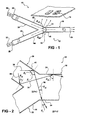
- FIG. 1 depicts a first embodiment of an illuminating interior article system of the present invention
- FIG. 2 is an enlarged, fragmentary view of the branching waveguide shown in FIG. 1;
- FIG. 3 is an enlarged, fragmentary view of a first alternative branch segment of the waveguide of FIG. 1 using notches to produce lateral illumination from the waveguide;
- FIG. 4 is an enlarged, fragmentary view of a second alternative branch segment of the waveguide of FIG. 1 using a stepped portion to promote light leakage from the branch segment;
- FIG. 5 depicts the use of a reflector and optical lens in conjunction with the waveguide of FIG. 1 to control the direction and dispersion of light from the junction of the waveguide;
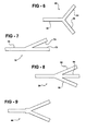
- FIGS. 6 - 14 depict various alternative embodiments of the waveguide of FIG. 1 that use different optical features to control the radiation of light out of the waveguide at the junction;
- FIG. 15 shows a first embodiment of a cupholder illuminating waveguide utilizing a Y-branch construction in accordance with the present invention
- FIG. 16 shows a second embodiment of a cupholder illuminating waveguide of the present invention
- FIG. 17 is an enlarged, fragmentary view of the cupholder waveguide of FIG. 16.
- FIG. 18 depicts an optical waveguide network which utilizes the branching waveguide of FIG. 1.
- an illuminated interior article system 10 that in general includes an optical waveguide 12 and a vehicle interior article 14 , which can be any of a number of different automotive interior components for which illumination is desired.
- Optical waveguide 12 is in the form of what is generally referred to as a Y-branch and is constructed in accordance with the present invention in a manner that provides illuminating light out of the waveguide 12 at its junction 16 . This enables the junction to be used not only to route light to different locations within the vehicle, but also to provide localized illumination of a nearby object or area.
- waveguide 12 would typically be located in a concealed location and used to provide direct, indirect, or backlighting of the interior article 14 .
- a backlit membrane switch 14 is shown, it will be appreciated that the interior article can be any of a wide variety of components, including cupholders, storage bins and trays, door handles, assist grips, seat buckles, and instrument panel displays and gauges.
- the light from junction 16 can be used for area illumination, whether it be as a dome light or as more localized illumination, such as a map light or foot well illumination.
- a stem 18 , a first branch 20 , and a second branch 22 each of which comprise a separate, elongated section of waveguide 12 that is formed from an optically transmissive material, such as acrylic, which is capable of transmitting light along its length by internal reflection of the light.
- an optically transmissive material such as acrylic, which is capable of transmitting light along its length by internal reflection of the light.
- One or more of these sections are optically coupled to a light source, with the waveguide 12 being used to route light received from the light source to a plurality of locations within the vehicle where the light is used to illuminate various objects or areas.
- any or all of the sections 18 , 20 , 22 can include other features or components, such as mounting tabs, coatings, color filters, electronically-controlled optical baffles, lenses, and other optical components.
- stem 18 extends from a terminal end 24 to junction 16 .
- branches 20 , 22 each extend from a respective terminal end 26 , 28 to junction 16 .
- Each of the sections 18 , 20 , 22 are optically joined together by junction 16 whether as a unitary molded structure or by way of a secondary operation using, for example, extruded pieces of optically-transmissive material.
- waveguide 12 is preferably one solid, homogeneous piece of light conducting material which does not have separable elements. These elements are only addressed individually for purposes of explaining the construction and optical properties of the waveguide.
- junction 16 extends from junction 16 at an obtuse angle relative to the direction of the stem section 18 at the point at which it connects to the branches at junction 16 .
- junction 16 is constructed such that a portion of the light entering the junction is transferred from one of the branches into the stem, or vice-a-versa, while simultaneously radiating another portion of that received light out of waveguide 12 and into the surrounding area to provide illumination of some vehicle interior article or area.
- junction 16 includes one or more optical features that are positioned at the junction such that a portion of the light traveling through one or more of the waveguide sections 18 , 20 , 22 impinges upon the optical feature(s) and is redirected out of the waveguide at the junction.
- optical features can be any of a wide variety of physical features which promote light leakage out of the waveguide 12 at junction 16 , including notches, stipplings, optical coatings, or outer surface configurations of the waveguide that are oriented at an angle relative to the direction of the impinging light such that the light is directed out of the waveguide rather than being internally reflected on.
- the optical features at junction 16 that results in illumination from the junction can be achieved by suitable selection of the angles between the branches 20 , 22 and stem section 18 so that a portion of the light is leaked out. This and many of the various other optical features possible are discussed below in connection with FIGS. 1 - 14 .
- waveguide 12 conducts light along its branches and stem by internal reflection of the light.
- the light can be introduced into any of the sections of the waveguide, typically by directing the light into one of the ends 24 , 26 , and/or 28 .
- light is directed into each of the branches 20 , 22 by light sources (illuminators) 30 , 32 , respectively.
- the two light sources can be used, if desired, to provide redundant illumination to stem 18 or to provide different brightness levels of light into stem 18 and out of the waveguide at junction 16 .
- two illuminators are shown, it will of course be appreciated that a single source can be used.
- the light can be inputted into the stem 18 , with the junction 16 serving not only to provide localized illumination out of the waveguide, but also to split the remaining light between the two branches 20 , 22 .
- the light from illuminators 30 , 32 travels along each branch by internal reflection and is delivered by the branches to the junction 16 .
- a first portion of the total light impinges on outer junction surface 34 of waveguide 12 at an angle less than the critical angle of the material.
- this portion of light is refracted out of junction 16 , instead of being totally internally reflected back into the waveguide.
- the remaining portion of the light entering junction 16 impinges on surface 34 at an angle greater than the critical angle and therefore internally reflects and is transmitted along to stem section 18 .
- each of the branches 20 , 22 are disposed at an obtuse angle ( ⁇ b1 , ⁇ b2 ) relative to stem 18 such that the outer surface 34 is oriented to direct a portion of the light out of the waveguide 12 at junction 16 .
- the proper orientation of outer surface 34 is achieved by suitable selection of the branch angles relative to stem section 18 as well as the dimensions of the branches and stem in the area of junction 16 .
- FIG. 2 where the paths of individual light rays 36 , 38 originating from light source 30 is shown.
- light ray 36 travels along branch 20 , internally reflecting at an angle ⁇ with respect to its outer surface 40 .
- the angle of incidence ( ⁇ i ) is defined as the angle between the light ray 36 and the line normal to outer surface 40 at the point of impingement:
- the outside environment 42 has an index of refraction (n 2 ), which is less than the index of refraction (n 1 ) for branch 20 .
- n 2 index of refraction
- ⁇ i angle of incidence
- ⁇ c critical angle
- the relative amount of light that is passed to stem 18 versus the amount that is radiated out of the waveguide depends upon the angle of incidence of the light with the outer surface 34 at the stem section. This angle is dependent on both the relative angle ⁇ b1 between the branch and stem, as well as the angle at which the light ray enters the junction 16 .
- ray 36 impinges outer surface 40 at an angle ⁇ i and is totally internally reflected back into branch 20 , as previously described.
- ⁇ t sin 31 1 [(n 1 /n 2 ) sin ⁇ i2 ].
- junction 16 Other light entering junction 16 will be passed on by internal reflection to stem 18 .
- light ray 38 impinges outer surface 40 at an angle ⁇ i3 , which is greater than the critical angle ( ⁇ i3 > ⁇ c ), such that the ray is internally reflected by outer surface 40 as it travels along branch 20 . It then enters junction 16 and strikes outer surface 34 at an angle ⁇ i4, that is greater than the critical angle, thereby being internally reflected and passing along into stem section 18 .
- This transmitted light has therefore passed through junction 16 into stem 18 without radiating out of the waveguide 12 .
- one portion of the light entering junction 16 is radiated out of the waveguide 12 and can be used for illumination purposes, while the remaining portion of the light is passed on through waveguide 12 and can be used remotely for other illumination purposes.
- the amount of light exiting the waveguide at junction 16 of this embodiment depends upon the angle of outer surface 40 relative to surface 34 (i.e., the angle ⁇ b1 ) as well as the maximum internally-reflected angle of the light traveling through branch 20 relative to its longitudinal axis, with this latter factor depending upon the entry angles of the light from illuminator 30 .
- directional control of the light radiated out of waveguide 12 at its junction 16 can be achieved using, for example, a reflective coating 46 applied to a portion of the outer surface of junction 16 .
- a reflective coating 46 applied to a portion of the outer surface of junction 16 .
- the light ray 36 shown in FIG. 2 can be reflected back into the waveguide at the lower side of junction 16 so that it will instead exit out of the upper part of junction 16 toward the vehicle interior article 14 .
- other optical coatings which also affect light leakage out of waveguide 12 at junction 16 can be used.
- a light-transmissive optical coating can be used to alter the critical angle ⁇ c and consequently could be used to either promote or further restrict light from escaping through the outer surface 34 .
- the individual sections 18 , 20 , 22 of waveguide 12 can have any of a variety of different cross-sectional shapes and dimensions, as will be appreciated by those skilled in the art. Also, the sections can have differing lengths, one or more bends, and other geometric and optical features in accordance with the particular application for which waveguide 12 is used. For example, as shown in FIG. 3, notches 48 can be used to provide lateral illumination out of the waveguide 12 at one or more locations. See also U.S. Pat. No. 5,432,876 to Appeldom et al. which discloses notching arrangements for providing such lateral illumination. Conversely, paint 50 or some other optical coating can be used on the branches and/or stem sections to reduce light leakage out of those sections. As shown in FIG. 4, a step down 52 in the thickness of the waveguide can also be used in a manner similar to notching to remove light from any of the sections of the waveguide for purposes of illuminating either an adjacent interior article or an area within the vehicle.
- various optical components can be used in connection with junction 16 to affect the light emission pattern out of the waveguide.
- these optical components include lenses, reflectors, filters, and other types of devices which can be used to effect a light pattern.
- a lens 54 could be mounted adjacent to junction 16 , such that the light which radiates out of junction 16 strikes the lens 54 and consequently is focused, directed, dispersed, or otherwise optically treated. Implementation of this design could aid in illuminating particular interior articles, or in gathering the emitted light to make a more efficient use of it.
- a separate reflector 56 can be used.
- reflector 56 can be mounted directly above the junction such that it was able to gather the light which was radiated upwards and redirect it downwards towards an article or area within the vehicle interior.
- surface treatments of the waveguide 12 at junction 16 can be used to remove a portion of the light. Examples of suitable surface treatments are shown in FIGS. 12 and 13 and are discussed further below. It will of course be understood that the lens and reflector shown in FIG. 5 could alternatively be positioned beside the junction rather than above and below it, and that both a lens and reflector need not necessarily be used together, the particular configuration being dependent upon the needs of a particular lighting application.
- FIGS. 6 - 17 a number of other embodiments of a Y-branch illuminating waveguide of the present invention are shown.
- the wide-branching waveguide 60 of FIG. 6 is similar to that of FIG. 1, except that the obtuse angle between the stem 62 and the branches 64 , 66 is much smaller than that of FIG. 1.
- the tapped waveguide 70 of FIG. 7 can be used to achieve an unequal division or contribution of light between the two branches 72 , 74 , whether by illumination originating from the stem 76 or the branches themselves.
- a waveguide 80 can have more than two branches; here, three branches 82 , 84 , 86 are shown.
- Increased illumination from the junction can be achieved using either the stepped junction of waveguide 90 in FIG. 9, the expanded-area waveguide 100 of FIG. 10, or a combination of the two, as shown by waveguide 110 of FIG. 11.
- waveguide 110 of FIG. 11 instead of different surface configurations at the junction, surface features and/or treatments of the junction can be used.
- the waveguide 120 of FIG. 12 includes notches 122 to promote light leakage at the junction 124 of that waveguide.
- the waveguide 130 of FIG. 13. includes stippling 132 for the same purpose.
- another waveguide embodiment 140 which includes a stem section 142 and first and second branches 144 , 146 which curve outwardly away from the junction 148 .
- This embodiment alters the radiation pattern as well as the amount of radiation emitting from junction 148 .
- Light rays 150 entering branch 144 will reflect within the bent section of branch 144 and then impinge outer surface 152 at angles which are less than the critical angle;
- the remaining rays such as light ray 154 , will impinge outer surface 152 at an angle beyond the critical angle of that interface, thereafter traveling down the length of stem section 142 to some remote location. It will of course be appreciated that numerous designs could be used which bend the branches as they enter junction 148 at different angles in order to affect the light emission at the junction.
- a Y-branch illuminating waveguide of the present invention is a cupholder illuminating waveguide 160 such as is shown in FIG. 15.
- This “wishbone” shaped waveguides 160 is configured for cupholders (not shown) having a gap 162 to accommodate a mug handle.
- Light for the waveguide 160 enters the input 164 of stem 166 and is split essentially equally to the two branches 168 , 170 of the wishbone.
- an optical feature in the form of a web portion 174 is included at the junction 172 between the two branches 168 , 170 .
- the web portion is thinner than the rest of the waveguide 160 (although it need not be) and provides additional illumination to the portion of the interior of the cupholder directly beneath the junction 172 .
- a cupholder illuminating waveguide 180 can utilize an optical feature in the form of a tab 182 that is thinner than the rest of the waveguide 180 and that extends downward from the junction 184 to reflect and/or transmit light toward the bottom of the cupholder.
- the tab 182 has a generally rectangular cross-section and curves downward toward the bottom of the cupholder.
- the tab 182 may have a chamfered leading edge 186 .
- waveguide 12 of FIG. 1 can be a part of a larger network 190 of waveguides, with the network including one or more other Y-branch waveguides, if desired.
- the illustrated network utilizes the transmitted light from one Y-branch waveguide to supply the adjacent waveguide.
- the light can originate from the stem or one or more branches.
- the light sources 30 , 32 supply the first and second branches 20 , 22 of waveguide 12 with illumination.
- a portion of the total light within waveguide 12 is radiated out of the device at its junction 16 , while the remaining portion is transmitted to a first branch 192 of another branching waveguide 194 .
- a second set of light sources 196 supply the branches 198 , 200 of a third waveguide 202 with illumination, with this waveguide being configured to pass all or substantially all of the illumination through the junction to its stem 204 without any significant light leakage at the junction 206 .
- the junction 206 could be configured if desired to radiate a portion of the total light out of the waveguide junction.
- Waveguide 194 is therefore receiving incident light from the stem sections of the two outer waveguides 12 , 202 , instead of from independent light sources. A portion of the light received by waveguide 194 is radiated out of the device at its junction 208 , while the remaining portion is transmitted to its stem section 210 .
- numerous combinations of waveguides could be coupled together to form various network configurations, with the construction of the network being determined by the specific parameters and requirements of the particular application for which the network is used.
Landscapes
- Physics & Mathematics (AREA)
- Engineering & Computer Science (AREA)
- Mechanical Engineering (AREA)
- General Physics & Mathematics (AREA)
- Optics & Photonics (AREA)
- Arrangements Of Lighting Devices For Vehicle Interiors, Mounting And Supporting Thereof, Circuits Therefore (AREA)
Abstract
Description
- This patent application is a continuation-in-part of U.S. Ser. No. 09/828,741, filed Apr. 9, 2001, which is a divisional of U.S. Ser. No. 09/109,051, filed Jul. 2, 1998, now U.S. Pat. No. 6,238,074, which is a continuation-in-part of U.S. Ser. No. 09/009,836, filed Jan. 20, 1998, now U.S. Pat. No. 6,168,302, and which claims the priority of provisional application Serial No. 60/069,118, filed, Dec. 9, 1997.
- This invention relates generally to waveguides used in vehicle illumination and, in particular, to branching optical junctions used in vehicle interior illumination.
- Traditionally, interior vehicle lighting has been accomplished by utilizing individual incandescent bulbs or other such light sources which are each dedicated to a single lighting function. The bulbs are placed at various locations throughout the vehicle where the illumination is needed and are energized by electrical power delivered via individual wires. As a result of the growing number of lighting applications within the vehicle, as well as the concomitant weight, cost, and power required by traditional lighting topologies, distributed lighting systems are becoming increasingly viable for use within the vehicle. These distributed lighting systems are typically implemented as light conducting networks that use fiber optics or other waveguides to deliver light from a relatively small number of light sources to remote areas of the vehicle. Generally, these remote areas are illuminated by light which is emitted from the distal end of each waveguide in conjunction with some type of lensing device, which aids in focusing, dispersing, or otherwise affecting the emitted light pattern. Many light conducting networks have been proposed over the years that cover a wide spectrum of characteristics and features.
- For example, U.S. Pat. No. 5,452,186, issued Sep. 19, 1995 to Dassanayake, discloses a light distribution system which utilizes a single light source and a multitude of waveguides to illuminate various components throughout a vehicle, such as an instrument panel, interior dome light, vanity mirror and sun visor. The light source is optically coupled to a ring of waveguides, which are generally oriented perpendicular to the light source in order to receive the incident light. The incident light is then delivered through the waveguides to remote locations, where it radiates out of the waveguides for illumination of an adjacent article or region of the vehicle interior.
- Another apparatus for conducting light throughout a vehicle is disclosed in U.S. Pat. No. 5,465,194, issued Nov. 7, 1995 to Currie. The Currie patent discloses various embodiments for the delivery and illumination of light throughout a vehicle, and in one embodiment discloses a light conducting Y-branch. This Y-branch includes two input waveguides which are optically coupled to a single output waveguide at a junction. This junction is fitted with a plano-convex lens which focuses the incident light from both input waveguides and therefore transmits all of the entering light to the single waveguide without any radiation out of the junction. The Y-branch arrangement disclosed by Currie enables light of different wavelengths to be transmitted through the input waveguides and mixed at the junction to thereby control the color of light outputted by the single waveguide. This patent is typical of prior art Y-branch arrangements in that it is not designed to provide illuminating light from the junction; thus, any light exiting the junction is lost and wasted.
- In areas other than vehicle lighting, light distribution for purposes of illumination has also been proposed using a network of waveguides. See, for example, U.S. Pat. No. 4,721,350, issued Jan. 26, 1988 to Mori, which discloses a light distribution network that can gather light from a single source and deliver it throughout an entire office building. In one particular embodiment, Mori discloses a branching optical junction which can act as a photo-radiator to thereby illuminate the surrounding area. This embodiment includes a main light conducting channel with a transverse bore extending through it and a secondary light conducting channel that fits within the transverse bore. The distal end of the secondary channel is a mirrored, angled end which extends into the bore and thereby obstructs the light traveling within the main channel. As the light travels along the main channel, it impinges the angled end which acts as a reflection surface, diverting at least a portion of the light out of the main channel. Typically, the diverted light is distributed to the secondary channel, which then delivers the light to a remote area. However, the angled end can be used as a reflecting element for illuminating the immediately surrounding area. Instead of diverting light into a secondary channel, the mirrored surface of the angled end is used to reflect the light out the other end of the bore, which is open. In this sense, light traveling along the main channel impinges this angled surface, and thereby reflects the incident light out of the open end of the bore and illuminates the surrounding area. The angled end can be positioned at various depths within the transverse bore, and can assume different angles, both of which affect the amount of light which is diverted.
- The optical junction in the Mori patent utilizes two separate waveguides which are not permanently affixed to each other. While this allows the position of the secondary, or branching, waveguide to be adjusted to different depths within the transverse bore, such a construction is believed to be overly complex for an automotive interior lighting system and therefore unnecessarily expensive and difficult to implement.
- Thus, there exists a need for a branching waveguide for automotive lighting systems and other such light distribution systems that makes use of the light exiting the waveguide at the branching junction.
- In accordance with the present invention there is provided an illuminated interior article system for use as a part of a vehicle interior lighting system. It includes a branching optical waveguide and a vehicle interior article positioned relative to waveguide such that the illuminating light exiting the waveguide at its junction illuminates the vehicle interior article, whether by direct, indirect, or backlit illumination. The branching waveguide has a stem, first and second branches, and a junction that couples the stem to each of the branches. The stem and branches each comprise an elongated section of the waveguide formed from an opticallytransmissive material that is capable of conducting light along its length by internal reflection of the light. The first and second branches extend away from the junction at an obtuse angle relative to the stem and the junction includes one or more optical features positioned at the junction such that a portion of the light traveling through one or more of the waveguide sections impinges upon the optical feature(s), with the optical feature(s) redirecting the impinging light out of the waveguide at the junction to thereby provide illuminating light from the junction. Rather than attempting to minimize light leakage at the waveguide junction, as is done in other branching waveguide light distribution systems, the waveguide of the present invention allows light to be selectively leaked from the junction for purposes of illumination.
- The optical features used to radiate light out of the waveguide at the junction can be any of a wide variety of physical features which promote light leakage including notches, stipplings, optical coatings, or outer surface configurations of the waveguide that are oriented at an angle relative to the direction of the impinging light such that the light is directed out of the waveguide rather than being internally reflected.
- A preferred exemplary embodiment of the present invention will hereinafter be described in conjunction with the appended drawings, wherein like designations denote like elements, and:
- FIG. 1 depicts a first embodiment of an illuminating interior article system of the present invention;
- FIG. 2 is an enlarged, fragmentary view of the branching waveguide shown in FIG. 1;
- FIG. 3 is an enlarged, fragmentary view of a first alternative branch segment of the waveguide of FIG. 1 using notches to produce lateral illumination from the waveguide;
- FIG. 4 is an enlarged, fragmentary view of a second alternative branch segment of the waveguide of FIG. 1 using a stepped portion to promote light leakage from the branch segment;
- FIG. 5 depicts the use of a reflector and optical lens in conjunction with the waveguide of FIG. 1 to control the direction and dispersion of light from the junction of the waveguide;
- FIGS. 6-14 depict various alternative embodiments of the waveguide of FIG. 1 that use different optical features to control the radiation of light out of the waveguide at the junction;
- FIG. 15 shows a first embodiment of a cupholder illuminating waveguide utilizing a Y-branch construction in accordance with the present invention;
- FIG. 16 shows a second embodiment of a cupholder illuminating waveguide of the present invention;
- FIG. 17 is an enlarged, fragmentary view of the cupholder waveguide of FIG. 16; and
- FIG. 18 depicts an optical waveguide network which utilizes the branching waveguide of FIG. 1.
- With reference to the FIG. 1, there is shown an illuminated
interior article system 10 that in general includes anoptical waveguide 12 and a vehicleinterior article 14, which can be any of a number of different automotive interior components for which illumination is desired.Optical waveguide 12 is in the form of what is generally referred to as a Y-branch and is constructed in accordance with the present invention in a manner that provides illuminating light out of thewaveguide 12 at itsjunction 16. This enables the junction to be used not only to route light to different locations within the vehicle, but also to provide localized illumination of a nearby object or area. It will be appreciated that the views depicted in the various figures are primarily diagrammatic, it being understood that some or all ofwaveguide 12 would typically be located in a concealed location and used to provide direct, indirect, or backlighting of theinterior article 14. Also, although abacklit membrane switch 14 is shown, it will be appreciated that the interior article can be any of a wide variety of components, including cupholders, storage bins and trays, door handles, assist grips, seat buckles, and instrument panel displays and gauges. Furthermore, it will also be appreciated that the light fromjunction 16 can be used for area illumination, whether it be as a dome light or as more localized illumination, such as a map light or foot well illumination. - Extending from
junction 16 is astem 18, afirst branch 20, and asecond branch 22, each of which comprise a separate, elongated section ofwaveguide 12 that is formed from an optically transmissive material, such as acrylic, which is capable of transmitting light along its length by internal reflection of the light. One or more of these sections are optically coupled to a light source, with thewaveguide 12 being used to route light received from the light source to a plurality of locations within the vehicle where the light is used to illuminate various objects or areas. Apart from simply being a section of thewaveguide 12, any or all of thesections - As shown,
stem 18 extends from aterminal end 24 tojunction 16. Similarly,branches terminal end junction 16. Each of thesections junction 16 whether as a unitary molded structure or by way of a secondary operation using, for example, extruded pieces of optically-transmissive material. In this regard, it is worth noting that while the various sections and elements ofwaveguide 12 are described separately,waveguide 12 is preferably one solid, homogeneous piece of light conducting material which does not have separable elements. These elements are only addressed individually for purposes of explaining the construction and optical properties of the waveguide. - Each branch extends from
junction 16 at an obtuse angle relative to the direction of thestem section 18 at the point at which it connects to the branches atjunction 16. As will be described below in connection with the various illustrated embodiments,junction 16 is constructed such that a portion of the light entering the junction is transferred from one of the branches into the stem, or vice-a-versa, while simultaneously radiating another portion of that received light out ofwaveguide 12 and into the surrounding area to provide illumination of some vehicle interior article or area. For this purpose,junction 16 includes one or more optical features that are positioned at the junction such that a portion of the light traveling through one or more of thewaveguide sections waveguide 12 atjunction 16, including notches, stipplings, optical coatings, or outer surface configurations of the waveguide that are oriented at an angle relative to the direction of the impinging light such that the light is directed out of the waveguide rather than being internally reflected on. In this regard, the optical features atjunction 16 that results in illumination from the junction can be achieved by suitable selection of the angles between thebranches stem section 18 so that a portion of the light is leaked out. This and many of the various other optical features possible are discussed below in connection with FIGS. 1-14. - Before discussing the various different optical features that can be utilized to radiate light out of the
waveguide 12 atjunction 16, some of the common optical properties and considerations used in the different embodiments will first be described in connection with the embodiment shown in FIGS. 1 and 2. In general,waveguide 12 conducts light along its branches and stem by internal reflection of the light. The light can be introduced into any of the sections of the waveguide, typically by directing the light into one of theends branches stem 18 and out of the waveguide atjunction 16. Although two illuminators are shown, it will of course be appreciated that a single source can be used. Similarly, the light can be inputted into thestem 18, with thejunction 16 serving not only to provide localized illumination out of the waveguide, but also to split the remaining light between the twobranches - The light from
illuminators junction 16. Once the light entersjunction 16, a first portion of the total light impinges onouter junction surface 34 ofwaveguide 12 at an angle less than the critical angle of the material. As is commonly known in the art, this portion of light is refracted out ofjunction 16, instead of being totally internally reflected back into the waveguide. The remaining portion of thelight entering junction 16 impinges onsurface 34 at an angle greater than the critical angle and therefore internally reflects and is transmitted along to stemsection 18. Thus, in this embodiment, each of thebranches outer surface 34 is oriented to direct a portion of the light out of thewaveguide 12 atjunction 16. For this purpose, the proper orientation ofouter surface 34 is achieved by suitable selection of the branch angles relative to stemsection 18 as well as the dimensions of the branches and stem in the area ofjunction 16. - More specifically, reference is made to FIG. 2 where the paths of individual light rays 36, 38 originating from
light source 30 is shown. In FIG. 2,light ray 36 travels alongbranch 20, internally reflecting at an angle φ with respect to itsouter surface 40. The angle of incidence (θi) is defined as the angle between thelight ray 36 and the line normal toouter surface 40 at the point of impingement: - Angle of Incidence θi=90°−φ.
- The outside environment 42 has an index of refraction (n2), which is less than the index of refraction (n1) for
branch 20. At the point whereray 36 strikesouter surface 40, if the angle of incidence (θi) is greater than the critical angle (θc), the ray will be totally internally reflected back intobranch 20, as commonly known in the art. The critical angle can be determined according to the equation: - Critical angle θc=sin−1(n2/n1).
- Therefore, light rays which impinge
outer surface 40 at an angle greater than the critical angle (θi>θc) will be totally internally reflected back intobranch 20 and will continue to travel along the length of the branch towardsjunction 16. This analysis applies equally to the light generated fromlight source 32 that impinges upon theouter surface 44 ofsecond branch 22. - Once the light originating from
illuminators junction 16, the relative amount of light that is passed to stem 18 versus the amount that is radiated out of the waveguide depends upon the angle of incidence of the light with theouter surface 34 at the stem section. This angle is dependent on both the relative angle θb1 between the branch and stem, as well as the angle at which the light ray enters thejunction 16. For example,ray 36 impingesouter surface 40 at an angle θi and is totally internally reflected back intobranch 20, as previously described. Even thoughray 36 is reflected fromouter surface 40 at an angle θr which is equal to θi (θi=θr),ray 36 will impinge theouter surface 34 atjunction 16 with an angle of incidence θi2 which is different than θi (i.e., θi2≠θi). This difference in incident angles is due to the fact thatouter surfaces light ray 36, its angle of incidence θi2 is less than the critical angle θc, resulting in theray 36 radiating out of thewaveguide 12 atjunction 16. As is known, the angle θt at which thelight ray 36 leaves the waveguide is governed by Snell's law: - Snell's Law n1 sin θi2=n2 sin θt,
- which can be rewritten to determine the exit angle:
- θt=sin31 1[(n1/n2) sin θi2].
- Other
light entering junction 16 will be passed on by internal reflection to stem 18. For example,light ray 38 impingesouter surface 40 at an angle θi3, which is greater than the critical angle (θi3>θc), such that the ray is internally reflected byouter surface 40 as it travels alongbranch 20. It then entersjunction 16 and strikesouter surface 34 at an angle θi4, that is greater than the critical angle, thereby being internally reflected and passing along intostem section 18. This transmitted light has therefore passed throughjunction 16 intostem 18 without radiating out of thewaveguide 12. Thus, it will be appreciated that one portion of thelight entering junction 16 is radiated out of thewaveguide 12 and can be used for illumination purposes, while the remaining portion of the light is passed on throughwaveguide 12 and can be used remotely for other illumination purposes. As will also be appreciated, the amount of light exiting the waveguide atjunction 16 of this embodiment depends upon the angle ofouter surface 40 relative to surface 34 (i.e., the angle θb1) as well as the maximum internally-reflected angle of the light traveling throughbranch 20 relative to its longitudinal axis, with this latter factor depending upon the entry angles of the light fromilluminator 30. - Referring back momentarily to FIG. 1, directional control of the light radiated out of
waveguide 12 at itsjunction 16 can be achieved using, for example, areflective coating 46 applied to a portion of the outer surface ofjunction 16. In this way, thelight ray 36 shown in FIG. 2 can be reflected back into the waveguide at the lower side ofjunction 16 so that it will instead exit out of the upper part ofjunction 16 toward the vehicleinterior article 14. In addition to or in lieu ofreflective coating 46, other optical coatings which also affect light leakage out ofwaveguide 12 atjunction 16 can be used. For example, a light-transmissive optical coating can be used to alter the critical angle θc and consequently could be used to either promote or further restrict light from escaping through theouter surface 34. - The
individual sections waveguide 12 can have any of a variety of different cross-sectional shapes and dimensions, as will be appreciated by those skilled in the art. Also, the sections can have differing lengths, one or more bends, and other geometric and optical features in accordance with the particular application for which waveguide 12 is used. For example, as shown in FIG. 3,notches 48 can be used to provide lateral illumination out of thewaveguide 12 at one or more locations. See also U.S. Pat. No. 5,432,876 to Appeldom et al. which discloses notching arrangements for providing such lateral illumination. Conversely, paint 50 or some other optical coating can be used on the branches and/or stem sections to reduce light leakage out of those sections. As shown in FIG. 4, a step down 52 in the thickness of the waveguide can also be used in a manner similar to notching to remove light from any of the sections of the waveguide for purposes of illuminating either an adjacent interior article or an area within the vehicle. - As shown in FIG. 5, various optical components can be used in connection with
junction 16 to affect the light emission pattern out of the waveguide. Examples of these optical components include lenses, reflectors, filters, and other types of devices which can be used to effect a light pattern. For instance, alens 54 could be mounted adjacent tojunction 16, such that the light which radiates out ofjunction 16 strikes thelens 54 and consequently is focused, directed, dispersed, or otherwise optically treated. Implementation of this design could aid in illuminating particular interior articles, or in gathering the emitted light to make a more efficient use of it. Also, rather than using thereflective coating 46 of FIG. 1 to control the direction of lateral illumination from thejunction 16, aseparate reflector 56 can be used. Thus, for example, if thewaveguide 12 is mounted in the headliner area of a vehicle interior and light radiates out ofjunction 16 in a omni-directional manner,reflector 56 can be mounted directly above the junction such that it was able to gather the light which was radiated upwards and redirect it downwards towards an article or area within the vehicle interior. For the relative location of thelens 54 andreflector 56 shown in FIG. 5, surface treatments of thewaveguide 12 atjunction 16 can be used to remove a portion of the light. Examples of suitable surface treatments are shown in FIGS. 12 and 13 and are discussed further below. It will of course be understood that the lens and reflector shown in FIG. 5 could alternatively be positioned beside the junction rather than above and below it, and that both a lens and reflector need not necessarily be used together, the particular configuration being dependent upon the needs of a particular lighting application. - Referring now to FIGS. 6-17, a number of other embodiments of a Y-branch illuminating waveguide of the present invention are shown. The wide-branching
waveguide 60 of FIG. 6 is similar to that of FIG. 1, except that the obtuse angle between thestem 62 and thebranches waveguide 70 of FIG. 7 can be used to achieve an unequal division or contribution of light between the twobranches stem 76 or the branches themselves. As shown in FIG. 8, awaveguide 80 can have more than two branches; here, threebranches waveguide 90 in FIG. 9, the expanded-area waveguide 100 of FIG. 10, or a combination of the two, as shown bywaveguide 110 of FIG. 11. Instead of different surface configurations at the junction, surface features and/or treatments of the junction can be used. For example, thewaveguide 120 of FIG. 12 includesnotches 122 to promote light leakage at thejunction 124 of that waveguide. Similarly, thewaveguide 130 of FIG. 13. includes stippling 132 for the same purpose. These surface features of FIGS. 12 and 13 would not affect the indices of refraction like a light-transmissive optical coating, but would alter the various angles at which the light strikes the outer surfaces of the light conducting channels, thereby promoting localized radial illumination at the junction where the features are located. - Referring now to FIG. 14, another
waveguide embodiment 140 is disclosed which includes a stem section 142 and first andsecond branches junction 148. This embodiment alters the radiation pattern as well as the amount of radiation emitting fromjunction 148.Light rays 150 enteringbranch 144 will reflect within the bent section ofbranch 144 and then impingeouter surface 152 at angles which are less than the critical angle; - consequently, they are transmitted out of the
junction 148 into the surrounding area. - The remaining rays, such as
light ray 154, will impingeouter surface 152 at an angle beyond the critical angle of that interface, thereafter traveling down the length of stem section 142 to some remote location. It will of course be appreciated that numerous designs could be used which bend the branches as they enterjunction 148 at different angles in order to affect the light emission at the junction. - One practical implementation of a Y-branch illuminating waveguide of the present invention is a
cupholder illuminating waveguide 160 such as is shown in FIG. 15. This “wishbone” shapedwaveguides 160 is configured for cupholders (not shown) having agap 162 to accommodate a mug handle. Light for thewaveguide 160 enters theinput 164 ofstem 166 and is split essentially equally to the twobranches junction 172, an optical feature in the form of aweb portion 174 is included at thejunction 172 between the twobranches junction 172. - Alternatively, as shown in FIG. 16, a
cupholder illuminating waveguide 180 can utilize an optical feature in the form of atab 182 that is thinner than the rest of thewaveguide 180 and that extends downward from thejunction 184 to reflect and/or transmit light toward the bottom of the cupholder. Thetab 182 has a generally rectangular cross-section and curves downward toward the bottom of the cupholder. - As shown in FIG. 17, the
tab 182 may have a chamfered leadingedge 186. - Turning next to FIG. 18,
waveguide 12 of FIG. 1 can be a part of alarger network 190 of waveguides, with the network including one or more other Y-branch waveguides, if desired. The illustrated network utilizes the transmitted light from one Y-branch waveguide to supply the adjacent waveguide. The light can originate from the stem or one or more branches. As shown, thelight sources second branches waveguide 12 with illumination. A portion of the total light withinwaveguide 12 is radiated out of the device at itsjunction 16, while the remaining portion is transmitted to afirst branch 192 of another branchingwaveguide 194. A second set oflight sources 196 supply thebranches third waveguide 202 with illumination, with this waveguide being configured to pass all or substantially all of the illumination through the junction to itsstem 204 without any significant light leakage at thejunction 206. Of course, thejunction 206 could be configured if desired to radiate a portion of the total light out of the waveguide junction.Waveguide 194 is therefore receiving incident light from the stem sections of the twoouter waveguides waveguide 194 is radiated out of the device at itsjunction 208, while the remaining portion is transmitted to itsstem section 210. As will be appreciated, numerous combinations of waveguides could be coupled together to form various network configurations, with the construction of the network being determined by the specific parameters and requirements of the particular application for which the network is used. - It will thus be apparent that there has been provided in accordance with the present invention an illuminated interior article system and Y-branch waveguide therefor which achieves the aims and advantages specified herein. It will, of course, be understood that the foregoing description is of preferred exemplary embodiments of the invention and that the invention is not limited to the specific embodiments shown. Various changes and modifications will become apparent to those skilled in the art and all such changes and modifications are intended to be within the scope of the present invention.
Claims (22)
Priority Applications (1)
| Application Number | Priority Date | Filing Date | Title |
|---|---|---|---|
| US10/097,697 US6733166B2 (en) | 1997-12-09 | 2002-03-13 | Illuminated interior article system utilizing a Y-branch waveguide |
Applications Claiming Priority (5)
| Application Number | Priority Date | Filing Date | Title |
|---|---|---|---|
| US6911897P | 1997-12-09 | 1997-12-09 | |
| US09/009,836 US6168302B1 (en) | 1997-12-09 | 1998-01-20 | Hybrid distributed lighting system for a vehicle |
| US09/109,051 US6238074B1 (en) | 1997-12-09 | 1998-07-02 | Optical waveguide structures |
| US09/828,741 US6554462B2 (en) | 1997-12-09 | 2001-04-09 | Optical waveguide structures |
| US10/097,697 US6733166B2 (en) | 1997-12-09 | 2002-03-13 | Illuminated interior article system utilizing a Y-branch waveguide |
Related Parent Applications (1)
| Application Number | Title | Priority Date | Filing Date |
|---|---|---|---|
| US09/828,741 Continuation-In-Part US6554462B2 (en) | 1997-12-09 | 2001-04-09 | Optical waveguide structures |
Publications (2)
| Publication Number | Publication Date |
|---|---|
| US20020102058A1 true US20020102058A1 (en) | 2002-08-01 |
| US6733166B2 US6733166B2 (en) | 2004-05-11 |
Family
ID=27485906
Family Applications (1)
| Application Number | Title | Priority Date | Filing Date |
|---|---|---|---|
| US10/097,697 Expired - Lifetime US6733166B2 (en) | 1997-12-09 | 2002-03-13 | Illuminated interior article system utilizing a Y-branch waveguide |
Country Status (1)
| Country | Link |
|---|---|
| US (1) | US6733166B2 (en) |
Cited By (22)
| Publication number | Priority date | Publication date | Assignee | Title |
|---|---|---|---|---|
| US20050013141A1 (en) * | 2003-07-17 | 2005-01-20 | Espinoza-Ibarra Ricardo Ernesto | Method and system for independently displaying a plurality of visual signals |
| US20070121313A1 (en) * | 2005-11-24 | 2007-05-31 | Siemens Aktiengesellschaft | Cockpit module |
| US20110141725A1 (en) * | 2009-12-11 | 2011-06-16 | Zinovi Brusilovsky | Variable-color lighting system |
| KR101053980B1 (en) * | 2008-11-13 | 2011-08-04 | 콘티넨탈 오토모티브 일렉트로닉스 유한회사 | Lighting equipment |
| WO2011094728A1 (en) * | 2010-02-01 | 2011-08-04 | Federal-Mogul Ignition Company | Illuminated vehicle cup holder assembly |
| US8162520B2 (en) | 2009-08-17 | 2012-04-24 | Toyota Motor Engineering & Manufacturing | Vehicle console assemblies with cup holder and storage bin lighting assembly |
| EP2620790A1 (en) * | 2012-01-25 | 2013-07-31 | Zizala Lichtsysteme GmbH | Lighting arrangement for vehicles |
| WO2014025777A1 (en) * | 2012-08-07 | 2014-02-13 | University Of South Alabama | Spectral illumination device and method |
| CN104023499A (en) * | 2013-03-01 | 2014-09-03 | 特拉博斯股份有限公司 | Electrical device |
| US20150062968A1 (en) * | 2013-09-03 | 2015-03-05 | Toshiba Lighting & Technology Corporation | Luminaire and Container Holder |
| US20150277027A1 (en) * | 2014-03-27 | 2015-10-01 | Koito Manufacturing Co., Ltd. | Vehicular lamp |
| US9187033B2 (en) * | 2010-08-25 | 2015-11-17 | Recaro Aircraft Seating Gmbh & Co. Kg | Passenger seat |
| EP3205926A1 (en) * | 2016-02-04 | 2017-08-16 | ZKW Group GmbH | Additive lens for the beam splitter of light guides |
| FR3051886A1 (en) * | 2016-05-31 | 2017-12-01 | Valeo Iluminacion Sa | LUMINOUS DEVICE, IN PARTICULAR FOR A MOTOR VEHICLE, AND LIGHTING AND / OR SIGNALING UNIT COMPRISING SUCH A LUMINOUS DEVICE. |
| DE102005029363B4 (en) * | 2005-06-24 | 2018-04-12 | Automotive Lighting Reutlingen Gmbh | Optical fiber structure |
| WO2018203910A1 (en) * | 2017-05-05 | 2018-11-08 | Ford Global Technologies, Llc | Vehicle lost object prevention |
| WO2019157477A1 (en) * | 2018-02-09 | 2019-08-15 | Neiser Paul | Filtration apparatus and method |
| WO2020086675A1 (en) * | 2018-10-23 | 2020-04-30 | Sigma International | Lighted device useful in a vehicle interior |
| US11099316B1 (en) * | 2020-03-20 | 2021-08-24 | Varroc Lighting Systems, s.r.o. | Light assembly with a multi-branched light guide device |
| US11260330B2 (en) | 2018-02-09 | 2022-03-01 | Paul NEISER | Filtration apparatus and method |
| US20220289104A1 (en) * | 2019-08-30 | 2022-09-15 | Motherson Innovations Company Ltd. | Light assembly, vehicle design element, rear view device and door finisher |
| US11666924B2 (en) | 2018-02-15 | 2023-06-06 | Paul NEISER | Apparatus and methods for selectively transmitting objects |
Families Citing this family (15)
| Publication number | Priority date | Publication date | Assignee | Title |
|---|---|---|---|---|
| US20050094940A1 (en) * | 2003-09-25 | 2005-05-05 | Ju Gao | Integrated light source and optical waveguide and method |
| DE102005019093B4 (en) * | 2005-03-29 | 2007-02-08 | Fer Fahrzeugelektrik Gmbh | Vehicle lamp with a multi-membered light guide |
| DE102005035282A1 (en) * | 2005-07-28 | 2007-02-01 | Fischer Automotive Systems Gmbh | Arrangement for lighting of functional unit e.g. storage tray, in motor vehicles has light guide which guides light from light source whereby functional unit consists of light guide or part of light guide and light entry surface |
| US7703965B2 (en) * | 2005-09-23 | 2010-04-27 | Koninklijke Philips Electronics N.V. | Diffusing light system with light collector |
| US7654680B2 (en) * | 2006-02-28 | 2010-02-02 | Chrysler Group Llc | Console assembly |
| US7810969B2 (en) * | 2006-11-02 | 2010-10-12 | Ford Global Technologies, Llc | Ambient lighting for vehicle interior floor console |
| WO2008058194A2 (en) * | 2006-11-07 | 2008-05-15 | Collins & Aikman Products Co. | Luminous interior trim material |
| US20100238661A1 (en) * | 2009-03-20 | 2010-09-23 | Sylvan R. Shemitz Designs Incorporated | Asymmetrical light producing baffle and luminaire inclusive thereof |
| US20100246200A1 (en) * | 2009-03-30 | 2010-09-30 | Osram Sylvania Inc. | Automotive taillight light guide |
| FR3009064B1 (en) * | 2013-07-25 | 2015-07-24 | Valeo Systemes Thermiques | LIGHT DEVICE |
| KR20170039027A (en) * | 2015-09-30 | 2017-04-10 | 삼성디스플레이 주식회사 | Backlight unit and display apparatus including the same |
| JP6714379B2 (en) * | 2016-02-17 | 2020-06-24 | 株式会社小糸製作所 | Vehicle lighting |
| EP4210989B1 (en) | 2020-09-11 | 2026-02-25 | Shanghai Yanfeng Jinqiao Automotive Trim Systems Co. Ltd | Vehicle interior component |
| US11835217B2 (en) | 2021-05-06 | 2023-12-05 | Black & Decker Inc. | Light emitting assembly for a power tool |
| USD1017361S1 (en) | 2021-05-06 | 2024-03-12 | Black & Decker Inc. | Drill |
Family Cites Families (14)
| Publication number | Priority date | Publication date | Assignee | Title |
|---|---|---|---|---|
| US2259910A (en) | 1938-09-13 | 1941-10-21 | Bendix Aviat Corp | Sealing and illuminating means for indicating instruments |
| US4556279A (en) | 1981-11-09 | 1985-12-03 | Board Of Trustees Of The Leland Stanford Junior University | Passive fiber optic multiplexer |
| US4721350A (en) | 1983-12-06 | 1988-01-26 | Kei Mori | Light distribution arrangement |
| JPH0685035B2 (en) | 1986-01-29 | 1994-10-26 | 株式会社日立製作所 | Light switch |
| GB2191631B (en) | 1986-06-09 | 1990-01-31 | Stc Plc | Laser array |
| US5432876C1 (en) | 1992-10-19 | 2002-05-21 | Minnesota Mining & Mfg | Illumination devices and optical fibres for use therein |
| US5369554A (en) * | 1993-01-07 | 1994-11-29 | Ford Motor Company | Illuminator utilizing multiple light guides |
| US5400225A (en) | 1993-10-06 | 1995-03-21 | Currie; Joseph E. | Optical fiber illumination device |
| US5452186A (en) | 1994-03-30 | 1995-09-19 | Ford Motor Company | Light distribution system |
| US5515244A (en) | 1995-04-03 | 1996-05-07 | Apple Computer, Inc. | Light-transmitting pipe |
| JP3175559B2 (en) | 1995-07-03 | 2001-06-11 | 住友電装株式会社 | Manufacturing method of optical branching coupler |
| JP2746216B2 (en) | 1995-08-04 | 1998-05-06 | 日本電気株式会社 | Light switch |
| US5757995A (en) | 1995-12-27 | 1998-05-26 | Nhk Spring Co., Ltd. | Optical coupler |
| US5826963A (en) | 1996-02-27 | 1998-10-27 | General Electric Company | Low angle, dual port light coupling arrangement |
-
2002
- 2002-03-13 US US10/097,697 patent/US6733166B2/en not_active Expired - Lifetime
Cited By (35)
| Publication number | Priority date | Publication date | Assignee | Title |
|---|---|---|---|---|
| US20050013141A1 (en) * | 2003-07-17 | 2005-01-20 | Espinoza-Ibarra Ricardo Ernesto | Method and system for independently displaying a plurality of visual signals |
| DE102005029363B4 (en) * | 2005-06-24 | 2018-04-12 | Automotive Lighting Reutlingen Gmbh | Optical fiber structure |
| US20070121313A1 (en) * | 2005-11-24 | 2007-05-31 | Siemens Aktiengesellschaft | Cockpit module |
| US7354181B2 (en) | 2005-11-24 | 2008-04-08 | Siemens Aktiengesellschaft | Cockpit module |
| KR101053980B1 (en) * | 2008-11-13 | 2011-08-04 | 콘티넨탈 오토모티브 일렉트로닉스 유한회사 | Lighting equipment |
| US8162520B2 (en) | 2009-08-17 | 2012-04-24 | Toyota Motor Engineering & Manufacturing | Vehicle console assemblies with cup holder and storage bin lighting assembly |
| US20110141725A1 (en) * | 2009-12-11 | 2011-06-16 | Zinovi Brusilovsky | Variable-color lighting system |
| US8439526B2 (en) * | 2009-12-11 | 2013-05-14 | Zinovi Brusilovsky | Variable-color lighting system |
| WO2011094728A1 (en) * | 2010-02-01 | 2011-08-04 | Federal-Mogul Ignition Company | Illuminated vehicle cup holder assembly |
| US8485680B2 (en) | 2010-02-01 | 2013-07-16 | Federal-Mogul Ignition Company | Illuminated vehicle cup holder assembly |
| US9187033B2 (en) * | 2010-08-25 | 2015-11-17 | Recaro Aircraft Seating Gmbh & Co. Kg | Passenger seat |
| EP2620790A1 (en) * | 2012-01-25 | 2013-07-31 | Zizala Lichtsysteme GmbH | Lighting arrangement for vehicles |
| AU2013299770B2 (en) * | 2012-08-07 | 2017-07-20 | University Of South Alabama | Spectral illumination device and method |
| US10393964B2 (en) | 2012-08-07 | 2019-08-27 | The University Of South Alabama | Spectral illumination device and method |
| WO2014025777A1 (en) * | 2012-08-07 | 2014-02-13 | University Of South Alabama | Spectral illumination device and method |
| US20140247618A1 (en) * | 2013-03-01 | 2014-09-04 | Tellabs Oy | Electrical device |
| CN104023499A (en) * | 2013-03-01 | 2014-09-03 | 特拉博斯股份有限公司 | Electrical device |
| US9946002B2 (en) * | 2013-03-01 | 2018-04-17 | Coriant Oy | Electrical device |
| US20150062968A1 (en) * | 2013-09-03 | 2015-03-05 | Toshiba Lighting & Technology Corporation | Luminaire and Container Holder |
| US20150277027A1 (en) * | 2014-03-27 | 2015-10-01 | Koito Manufacturing Co., Ltd. | Vehicular lamp |
| US10072813B2 (en) * | 2014-03-27 | 2018-09-11 | Koito Manufacturing Co., Ltd. | Vehicular lamp having light guides extending in different directions |
| EP3205926A1 (en) * | 2016-02-04 | 2017-08-16 | ZKW Group GmbH | Additive lens for the beam splitter of light guides |
| FR3051886A1 (en) * | 2016-05-31 | 2017-12-01 | Valeo Iluminacion Sa | LUMINOUS DEVICE, IN PARTICULAR FOR A MOTOR VEHICLE, AND LIGHTING AND / OR SIGNALING UNIT COMPRISING SUCH A LUMINOUS DEVICE. |
| WO2018203910A1 (en) * | 2017-05-05 | 2018-11-08 | Ford Global Technologies, Llc | Vehicle lost object prevention |
| WO2019157477A1 (en) * | 2018-02-09 | 2019-08-15 | Neiser Paul | Filtration apparatus and method |
| US20190247885A1 (en) * | 2018-02-09 | 2019-08-15 | Paul NEISER | Filtration apparatus and method |
| JP2021514492A (en) * | 2018-02-09 | 2021-06-10 | ニーサー,ポール | Filtration equipment and methods |
| US11167313B2 (en) * | 2018-02-09 | 2021-11-09 | Paul NEISER | Filtration apparatus and method |
| US11260330B2 (en) | 2018-02-09 | 2022-03-01 | Paul NEISER | Filtration apparatus and method |
| US11666924B2 (en) | 2018-02-15 | 2023-06-06 | Paul NEISER | Apparatus and methods for selectively transmitting objects |
| WO2020086675A1 (en) * | 2018-10-23 | 2020-04-30 | Sigma International | Lighted device useful in a vehicle interior |
| US20220289104A1 (en) * | 2019-08-30 | 2022-09-15 | Motherson Innovations Company Ltd. | Light assembly, vehicle design element, rear view device and door finisher |
| US11840171B2 (en) * | 2019-08-30 | 2023-12-12 | Motherson Innovations Company Limited | Light assembly, vehicle design element, rear view device and door finisher |
| US12286052B2 (en) | 2019-08-30 | 2025-04-29 | Motherson Innovations Company Limited | Light assembly, vehicle design element, rear view device and door finisher |
| US11099316B1 (en) * | 2020-03-20 | 2021-08-24 | Varroc Lighting Systems, s.r.o. | Light assembly with a multi-branched light guide device |
Also Published As
| Publication number | Publication date |
|---|---|
| US6733166B2 (en) | 2004-05-11 |
Similar Documents
| Publication | Publication Date | Title |
|---|---|---|
| US6733166B2 (en) | Illuminated interior article system utilizing a Y-branch waveguide | |
| US5751870A (en) | Optical fiber lensed illumination coupler | |
| US6594417B1 (en) | Waveguide assembly for laterally-directed illumination in a vehicle lighting system | |
| US6880945B2 (en) | Lamp for vehicles | |
| US20220283356A1 (en) | Illumination Device for Direct-Indirect Illumination | |
| US6164805A (en) | Illuminated door handle for a vehicle | |
| US7438447B2 (en) | Apparatus and method for improved illumination area fill | |
| US10132988B2 (en) | Luminaire module with multiple light guide elements | |
| EP1114278B1 (en) | Illumination system using an edge-illuminated hollow waveguide and lenticular optical structures | |
| JP3410502B2 (en) | Lighting equipment for vehicles | |
| US4459642A (en) | Optical lighting device | |
| EP0977962A1 (en) | An illuminator | |
| JPH10513001A (en) | Light directing optical structure | |
| WO1999020937A1 (en) | Directed lighting system utilizing a conical light deflector | |
| US20090237943A1 (en) | Flush mount reading light | |
| CA2299532A1 (en) | Thin light managing system for directing and distributing light from one or more light sources and method for making optics structures for use in the system | |
| KR20020038603A (en) | Collecting and condensing optical system using cascaded parabolic reflectors | |
| US20220034463A1 (en) | Multi-beam vehicle light | |
| JPH06260006A (en) | Lighting equipment | |
| WO2008024733A2 (en) | Fiberoptic luminaire with scattering and specular side-light extractor patterns | |
| AU692397B2 (en) | Multiport illuminator for macro-fibers | |
| US6430339B1 (en) | Low profile waveguide system | |
| JPH09213114A (en) | Lighting system | |
| US20260052609A1 (en) | Luminaires for spatial dimming | |
| KR100463934B1 (en) | Back-coupled lighting system to regenerate light |
Legal Events
| Date | Code | Title | Description |
|---|---|---|---|
| AS | Assignment |
Owner name: FEDERAL-MOGUL WORLD WIDE, INC., MICHIGAN Free format text: ASSIGNMENT OF ASSIGNORS INTEREST;ASSIGNOR:HULSE, GEORGE ROBERT;REEL/FRAME:012871/0006 Effective date: 20020208 |
|
| STCF | Information on status: patent grant |
Free format text: PATENTED CASE |
|
| FPAY | Fee payment |
Year of fee payment: 4 |
|
| AS | Assignment |
Owner name: CITIBANK, N.A. AS COLLATERAL TRUSTEE, NEW YORK Free format text: SECURITY AGREEMENT;ASSIGNOR:FEDERAL-MOGUL WORLD WIDE, INC.;REEL/FRAME:020362/0139 Effective date: 20071227 Owner name: CITIBANK, N.A. AS COLLATERAL TRUSTEE,NEW YORK Free format text: SECURITY AGREEMENT;ASSIGNOR:FEDERAL-MOGUL WORLD WIDE, INC.;REEL/FRAME:020362/0139 Effective date: 20071227 |
|
| CC | Certificate of correction | ||
| FPAY | Fee payment |
Year of fee payment: 8 |
|
| AS | Assignment |
Owner name: CITIBANK, N.A., AS COLLATERAL TRUSTEE, DELAWARE Free format text: SECURITY INTEREST;ASSIGNORS:FEDERAL-MOGUL CORPORATION, A DELAWARE CORPORATION;FEDERAL-MOGUL WORLD WIDE, INC., A MICHIGAN CORPORATION;FEDERAL-MOGUL IGNITION COMPANY, A DELAWARE CORPORATION;AND OTHERS;REEL/FRAME:033204/0707 Effective date: 20140616 |
|
| FPAY | Fee payment |
Year of fee payment: 12 |
|
| AS | Assignment |
Owner name: CITIBANK, N.A., AS COLLATERAL TRUSTEE, NEW YORK Free format text: GRANT OF SECURITY INTEREST IN UNITED STATES PATENTS;ASSIGNORS:FEDERAL-MOGUL LLC;FEDERAL-MOGUL PRODUCTS, INC.;FEDERAL-MOGUL MOTORPARTS CORPORATION;AND OTHERS;REEL/FRAME:042963/0662 Effective date: 20170330 |
|
| AS | Assignment |
Owner name: CITIBANK, N.A., AS COLLATERAL TRUSTEE, NEW YORK Free format text: GRANT OF SECURITY INTEREST IN UNITED STATES PATENTS;ASSIGNORS:FEDERAL-MOGUL LLC;FEDERAL-MOGUL PRODUCTS, INC.;FEDERAL-MOGUL MOTORPARTS LLC;AND OTHERS;REEL/FRAME:044013/0419 Effective date: 20170629 |
|
| AS | Assignment |
Owner name: FEDERAL-MOGUL WORLD WIDE LLC, MICHIGAN Free format text: CHANGE OF NAME;ASSIGNOR:FEDERAL-MOGUL WORLD WIDE, INC.;REEL/FRAME:044033/0437 Effective date: 20170410 |
|
| AS | Assignment |
Owner name: FEDERAL-MOGUL MOTORPARTS LLC (F/K/A/ FEDERAL-MOGUL MOTORPARTS CORPORATION), MICHIGAN Free format text: RELEASE BY SECURED PARTY;ASSIGNOR:CITIBANK, N.A., AS COLLATERAL TRUSTEE AND AGENT;REEL/FRAME:044721/0032 Effective date: 20171204 Owner name: FEDERAL-MOGUL WORLD WIDE LLC (F/K/A/ FEDERAL-MOGUL WORLD WIDE, INC.), MICHIGAN Free format text: RELEASE BY SECURED PARTY;ASSIGNOR:CITIBANK, N.A., AS COLLATERAL TRUSTEE AND AGENT;REEL/FRAME:044721/0032 Effective date: 20171204 Owner name: FEDERAL-MOGUL PRODUCTS, INC., MICHIGAN Free format text: RELEASE BY SECURED PARTY;ASSIGNOR:CITIBANK, N.A., AS COLLATERAL TRUSTEE AND AGENT;REEL/FRAME:044721/0032 Effective date: 20171204 Owner name: FEDERAL-MOGUL MOTORPARTS LLC (F/K/A/ FEDERAL-MOGUL Free format text: RELEASE BY SECURED PARTY;ASSIGNOR:CITIBANK, N.A., AS COLLATERAL TRUSTEE AND AGENT;REEL/FRAME:044721/0032 Effective date: 20171204 Owner name: FEDERAL-MOGUL POWERTRAIN LLC, MICHIGAN Free format text: RELEASE BY SECURED PARTY;ASSIGNOR:CITIBANK, N.A., AS COLLATERAL TRUSTEE AND AGENT;REEL/FRAME:044721/0032 Effective date: 20171204 Owner name: FEDERAL-MOGUL CORPORATION, MICHIGAN Free format text: RELEASE BY SECURED PARTY;ASSIGNOR:CITIBANK, N.A., AS COLLATERAL TRUSTEE AND AGENT;REEL/FRAME:044721/0032 Effective date: 20171204 Owner name: FEDERAL-MOGUL IGNITION COMPANY, MICHIGAN Free format text: RELEASE BY SECURED PARTY;ASSIGNOR:CITIBANK, N.A., AS COLLATERAL TRUSTEE AND AGENT;REEL/FRAME:044721/0032 Effective date: 20171204 Owner name: FEDERAL-MOGUL, LLC, MICHIGAN Free format text: RELEASE BY SECURED PARTY;ASSIGNOR:CITIBANK, N.A., AS COLLATERAL TRUSTEE AND AGENT;REEL/FRAME:044721/0032 Effective date: 20171204 Owner name: FEDERAL-MOGUL POWERTRAIN, INC., MICHIGAN Free format text: RELEASE BY SECURED PARTY;ASSIGNOR:CITIBANK, N.A., AS COLLATERAL TRUSTEE AND AGENT;REEL/FRAME:044721/0032 Effective date: 20171204 Owner name: FEDERAL-MOGUL WORLD WIDE LLC (F/K/A/ FEDERAL-MOGUL Free format text: RELEASE BY SECURED PARTY;ASSIGNOR:CITIBANK, N.A., AS COLLATERAL TRUSTEE AND AGENT;REEL/FRAME:044721/0032 Effective date: 20171204 Owner name: FEDERAL-MOGUL CHASSIS LLC, MICHIGAN Free format text: RELEASE BY SECURED PARTY;ASSIGNOR:CITIBANK, N.A., AS COLLATERAL TRUSTEE AND AGENT;REEL/FRAME:044721/0032 Effective date: 20171204 |
|
| AS | Assignment |
Owner name: REBO LIGHTING & ELECTRONICS, LLC, MICHIGAN Free format text: ASSIGNMENT OF ASSIGNORS INTEREST;ASSIGNOR:FEDERAL-MOGUL WORLDWIDE LLC;REEL/FRAME:045551/0445 Effective date: 20171204 |
|
| AS | Assignment |
Owner name: DRIV AUTOMOTIVE INC., ILLINOIS Free format text: RELEASE BY SECURED PARTY;ASSIGNOR:WILMINGTON TRUST, NATIONAL ASSOCIATION;REEL/FRAME:058392/0274 Effective date: 20210317 Owner name: FEDERAL-MOGUL POWERTRAIN LLC, MICHIGAN Free format text: RELEASE BY SECURED PARTY;ASSIGNOR:WILMINGTON TRUST, NATIONAL ASSOCIATION;REEL/FRAME:058392/0274 Effective date: 20210317 Owner name: FEDERAL-MOGUL CHASSIS LLC, MICHIGAN Free format text: RELEASE BY SECURED PARTY;ASSIGNOR:WILMINGTON TRUST, NATIONAL ASSOCIATION;REEL/FRAME:058392/0274 Effective date: 20210317 Owner name: TENNECO INC., AS SUCCESSOR TO FEDERAL-MOGUL LLC, ILLINOIS Free format text: RELEASE BY SECURED PARTY;ASSIGNOR:WILMINGTON TRUST, NATIONAL ASSOCIATION;REEL/FRAME:058392/0274 Effective date: 20210317 Owner name: FEDERAL-MOGUL IGNITION, LLC, AS SUCCESSOR TO FEDERAL-MOGUL IGNITION COMPANY, MICHIGAN Free format text: RELEASE BY SECURED PARTY;ASSIGNOR:WILMINGTON TRUST, NATIONAL ASSOCIATION;REEL/FRAME:058392/0274 Effective date: 20210317 Owner name: FEDERAL-MOGUL MOTORPARTS LLC, AS SUCCESSOR TO FEDERAL-MOGUL MOTORPARTS CORPORATION, MICHIGAN Free format text: RELEASE BY SECURED PARTY;ASSIGNOR:WILMINGTON TRUST, NATIONAL ASSOCIATION;REEL/FRAME:058392/0274 Effective date: 20210317 Owner name: FEDERAL-MOGUL WORLD WIDE, INC., AS SUCCESSOR TO FEDERAL-MOGUL WORLD WIDE LLC, MICHIGAN Free format text: RELEASE BY SECURED PARTY;ASSIGNOR:WILMINGTON TRUST, NATIONAL ASSOCIATION;REEL/FRAME:058392/0274 Effective date: 20210317 Owner name: FEDERAL-MOGUL PRODUCTS US, LLC, AS SUCCESSOR TO FEDERAL-MOGUL PRODUCTS, INC., MICHIGAN Free format text: RELEASE BY SECURED PARTY;ASSIGNOR:WILMINGTON TRUST, NATIONAL ASSOCIATION;REEL/FRAME:058392/0274 Effective date: 20210317 Owner name: FEDERAL-MOGUL PRODUCTS US, LLC, AS SUCCESSOR TO FEDERAL-MOGUL PRODUCTS, INC., MICHIGAN Free format text: RELEASE BY SECURED PARTY;ASSIGNOR:WILMINGTON TRUST, NATIONAL ASSOCIATION;REEL/FRAME:056886/0455 Effective date: 20210317 Owner name: FEDERAL-MOGUL WORLD WIDE, INC., AS SUCCESSOR TO FEDERAL-MOGUL WORLD WIDE LLC, MICHIGAN Free format text: RELEASE BY SECURED PARTY;ASSIGNOR:WILMINGTON TRUST, NATIONAL ASSOCIATION;REEL/FRAME:056886/0455 Effective date: 20210317 Owner name: FEDERAL-MOGUL MOTORPARTS LLC, AS SUCCESSOR TO FEDERAL-MOGUL MOTORPARTS CORPORATION, MICHIGAN Free format text: RELEASE BY SECURED PARTY;ASSIGNOR:WILMINGTON TRUST, NATIONAL ASSOCIATION;REEL/FRAME:056886/0455 Effective date: 20210317 Owner name: FEDERAL-MOGUL IGNITION, LLC, AS SUCCESSOR TO FEDERAL-MOGUL IGNITION COMPANY, MICHIGAN Free format text: RELEASE BY SECURED PARTY;ASSIGNOR:WILMINGTON TRUST, NATIONAL ASSOCIATION;REEL/FRAME:056886/0455 Effective date: 20210317 Owner name: TENNECO INC., AS SUCCESSOR TO FEDERAL-MOGUL LLC, ILLINOIS Free format text: RELEASE BY SECURED PARTY;ASSIGNOR:WILMINGTON TRUST, NATIONAL ASSOCIATION;REEL/FRAME:056886/0455 Effective date: 20210317 Owner name: FEDERAL-MOGUL CHASSIS LLC, MICHIGAN Free format text: RELEASE BY SECURED PARTY;ASSIGNOR:WILMINGTON TRUST, NATIONAL ASSOCIATION;REEL/FRAME:056886/0455 Effective date: 20210317 Owner name: FEDERAL-MOGUL POWERTRAIN LLC, MICHIGAN Free format text: RELEASE BY SECURED PARTY;ASSIGNOR:WILMINGTON TRUST, NATIONAL ASSOCIATION;REEL/FRAME:056886/0455 Effective date: 20210317 Owner name: DRIV AUTOMOTIVE INC., ILLINOIS Free format text: RELEASE BY SECURED PARTY;ASSIGNOR:WILMINGTON TRUST, NATIONAL ASSOCIATION;REEL/FRAME:056886/0455 Effective date: 20210317 Owner name: FEDERAL-MOGUL PRODUCTS US, LLC, AS SUCCESSOR TO FEDERAL-MOGUL PRODUCTS, INC., MICHIGAN Free format text: RELEASE OF SECURITY INTEREST;ASSIGNOR:WILMINGTON TRUST, NATIONAL ASSOCIATION;REEL/FRAME:058392/0274 Effective date: 20210317 Owner name: FEDERAL-MOGUL WORLD WIDE, INC., AS SUCCESSOR TO FEDERAL-MOGUL WORLD WIDE LLC, MICHIGAN Free format text: RELEASE OF SECURITY INTEREST;ASSIGNOR:WILMINGTON TRUST, NATIONAL ASSOCIATION;REEL/FRAME:058392/0274 Effective date: 20210317 Owner name: FEDERAL-MOGUL MOTORPARTS LLC, AS SUCCESSOR TO FEDERAL-MOGUL MOTORPARTS CORPORATION, MICHIGAN Free format text: RELEASE OF SECURITY INTEREST;ASSIGNOR:WILMINGTON TRUST, NATIONAL ASSOCIATION;REEL/FRAME:058392/0274 Effective date: 20210317 Owner name: FEDERAL-MOGUL IGNITION, LLC, AS SUCCESSOR TO FEDERAL-MOGUL IGNITION COMPANY, MICHIGAN Free format text: RELEASE OF SECURITY INTEREST;ASSIGNOR:WILMINGTON TRUST, NATIONAL ASSOCIATION;REEL/FRAME:058392/0274 Effective date: 20210317 Owner name: TENNECO INC., AS SUCCESSOR TO FEDERAL-MOGUL LLC, ILLINOIS Free format text: RELEASE OF SECURITY INTEREST;ASSIGNOR:WILMINGTON TRUST, NATIONAL ASSOCIATION;REEL/FRAME:058392/0274 Effective date: 20210317 Owner name: FEDERAL-MOGUL CHASSIS LLC, MICHIGAN Free format text: RELEASE OF SECURITY INTEREST;ASSIGNOR:WILMINGTON TRUST, NATIONAL ASSOCIATION;REEL/FRAME:058392/0274 Effective date: 20210317 Owner name: FEDERAL-MOGUL POWERTRAIN LLC, MICHIGAN Free format text: RELEASE OF SECURITY INTEREST;ASSIGNOR:WILMINGTON TRUST, NATIONAL ASSOCIATION;REEL/FRAME:058392/0274 Effective date: 20210317 Owner name: DRIV AUTOMOTIVE INC., ILLINOIS Free format text: RELEASE OF SECURITY INTEREST;ASSIGNOR:WILMINGTON TRUST, NATIONAL ASSOCIATION;REEL/FRAME:058392/0274 Effective date: 20210317 Owner name: FEDERAL-MOGUL PRODUCTS US, LLC, AS SUCCESSOR TO FEDERAL-MOGUL PRODUCTS, INC., MICHIGAN Free format text: RELEASE OF SECURITY INTEREST;ASSIGNOR:WILMINGTON TRUST, NATIONAL ASSOCIATION;REEL/FRAME:056886/0455 Effective date: 20210317 Owner name: FEDERAL-MOGUL WORLD WIDE, INC., AS SUCCESSOR TO FEDERAL-MOGUL WORLD WIDE LLC, MICHIGAN Free format text: RELEASE OF SECURITY INTEREST;ASSIGNOR:WILMINGTON TRUST, NATIONAL ASSOCIATION;REEL/FRAME:056886/0455 Effective date: 20210317 Owner name: FEDERAL-MOGUL MOTORPARTS LLC, AS SUCCESSOR TO FEDERAL-MOGUL MOTORPARTS CORPORATION, MICHIGAN Free format text: RELEASE OF SECURITY INTEREST;ASSIGNOR:WILMINGTON TRUST, NATIONAL ASSOCIATION;REEL/FRAME:056886/0455 Effective date: 20210317 Owner name: FEDERAL-MOGUL IGNITION, LLC, AS SUCCESSOR TO FEDERAL-MOGUL IGNITION COMPANY, MICHIGAN Free format text: RELEASE OF SECURITY INTEREST;ASSIGNOR:WILMINGTON TRUST, NATIONAL ASSOCIATION;REEL/FRAME:056886/0455 Effective date: 20210317 Owner name: TENNECO INC., AS SUCCESSOR TO FEDERAL-MOGUL LLC, ILLINOIS Free format text: RELEASE OF SECURITY INTEREST;ASSIGNOR:WILMINGTON TRUST, NATIONAL ASSOCIATION;REEL/FRAME:056886/0455 Effective date: 20210317 Owner name: FEDERAL-MOGUL CHASSIS LLC, MICHIGAN Free format text: RELEASE OF SECURITY INTEREST;ASSIGNOR:WILMINGTON TRUST, NATIONAL ASSOCIATION;REEL/FRAME:056886/0455 Effective date: 20210317 Owner name: FEDERAL-MOGUL POWERTRAIN LLC, MICHIGAN Free format text: RELEASE OF SECURITY INTEREST;ASSIGNOR:WILMINGTON TRUST, NATIONAL ASSOCIATION;REEL/FRAME:056886/0455 Effective date: 20210317 Owner name: DRIV AUTOMOTIVE INC., ILLINOIS Free format text: RELEASE OF SECURITY INTEREST;ASSIGNOR:WILMINGTON TRUST, NATIONAL ASSOCIATION;REEL/FRAME:056886/0455 Effective date: 20210317 |
|
| AS | Assignment |
Owner name: FEDERAL-MOGUL WORLD WIDE LLC (FORMERLY FEDERAL-MOGUL WORLD WIDE, INC.), MICHIGAN Free format text: RELEASE BY SECURED PARTY;ASSIGNOR:CITIBANK, N.A.;REEL/FRAME:062389/0149 Effective date: 20230112 |