US20020048368A1 - Method and apparatus for medium access control in powerline communication network systems - Google Patents
Method and apparatus for medium access control in powerline communication network systems Download PDFInfo
- Publication number
- US20020048368A1 US20020048368A1 US09/876,454 US87645401A US2002048368A1 US 20020048368 A1 US20020048368 A1 US 20020048368A1 US 87645401 A US87645401 A US 87645401A US 2002048368 A1 US2002048368 A1 US 2002048368A1
- Authority
- US
- United States
- Prior art keywords
- reservation
- devices
- message
- encryption key
- payload
- Prior art date
- Legal status (The legal status is an assumption and is not a legal conclusion. Google has not performed a legal analysis and makes no representation as to the accuracy of the status listed.)
- Granted
Links
- 238000000034 method Methods 0.000 title claims abstract description 181
- 238000004891 communication Methods 0.000 title claims description 100
- 230000006855 networking Effects 0.000 claims abstract description 94
- 108700026140 MAC combination Proteins 0.000 claims abstract description 55
- 230000005540 biological transmission Effects 0.000 claims description 66
- 230000002441 reversible effect Effects 0.000 claims description 8
- 238000012937 correction Methods 0.000 claims description 4
- 238000013478 data encryption standard Methods 0.000 claims description 4
- 125000004122 cyclic group Chemical group 0.000 claims description 3
- 238000009434 installation Methods 0.000 claims description 3
- 238000012544 monitoring process Methods 0.000 claims description 2
- 238000013519 translation Methods 0.000 claims 1
- 230000007246 mechanism Effects 0.000 abstract description 8
- 238000007726 management method Methods 0.000 description 28
- 238000013459 approach Methods 0.000 description 22
- 230000008569 process Effects 0.000 description 15
- 230000006870 function Effects 0.000 description 11
- 230000001934 delay Effects 0.000 description 10
- 230000000737 periodic effect Effects 0.000 description 8
- 238000010586 diagram Methods 0.000 description 7
- 238000012546 transfer Methods 0.000 description 7
- 238000005516 engineering process Methods 0.000 description 6
- 238000012986 modification Methods 0.000 description 6
- 230000004048 modification Effects 0.000 description 6
- 230000008901 benefit Effects 0.000 description 4
- 238000013461 design Methods 0.000 description 3
- 230000004044 response Effects 0.000 description 3
- 238000007792 addition Methods 0.000 description 2
- 230000002238 attenuated effect Effects 0.000 description 2
- 230000015556 catabolic process Effects 0.000 description 2
- 230000008859 change Effects 0.000 description 2
- 238000006731 degradation reaction Methods 0.000 description 2
- 238000011900 installation process Methods 0.000 description 2
- 230000002452 interceptive effect Effects 0.000 description 2
- 238000004806 packaging method and process Methods 0.000 description 2
- 230000001902 propagating effect Effects 0.000 description 2
- 230000011664 signaling Effects 0.000 description 2
- 238000001228 spectrum Methods 0.000 description 2
- 206010009944 Colon cancer Diseases 0.000 description 1
- 108091081062 Repeated sequence (DNA) Proteins 0.000 description 1
- 230000003044 adaptive effect Effects 0.000 description 1
- 230000003466 anti-cipated effect Effects 0.000 description 1
- 230000003542 behavioural effect Effects 0.000 description 1
- 238000004364 calculation method Methods 0.000 description 1
- 230000006735 deficit Effects 0.000 description 1
- 238000011161 development Methods 0.000 description 1
- 230000000694 effects Effects 0.000 description 1
- 230000006872 improvement Effects 0.000 description 1
- 238000003973 irrigation Methods 0.000 description 1
- 230000002262 irrigation Effects 0.000 description 1
- 238000013507 mapping Methods 0.000 description 1
- 230000000704 physical effect Effects 0.000 description 1
- 230000000644 propagated effect Effects 0.000 description 1
- 238000011160 research Methods 0.000 description 1
- 238000012552 review Methods 0.000 description 1
- 238000012360 testing method Methods 0.000 description 1
- 238000005406 washing Methods 0.000 description 1
Images


Classifications
-
- H—ELECTRICITY
- H04—ELECTRIC COMMUNICATION TECHNIQUE
- H04L—TRANSMISSION OF DIGITAL INFORMATION, e.g. TELEGRAPHIC COMMUNICATION
- H04L63/00—Network architectures or network communication protocols for network security
- H04L63/04—Network architectures or network communication protocols for network security for providing a confidential data exchange among entities communicating through data packet networks
- H04L63/0428—Network architectures or network communication protocols for network security for providing a confidential data exchange among entities communicating through data packet networks wherein the data content is protected, e.g. by encrypting or encapsulating the payload
-
- H—ELECTRICITY
- H04—ELECTRIC COMMUNICATION TECHNIQUE
- H04B—TRANSMISSION
- H04B3/00—Line transmission systems
- H04B3/54—Systems for transmission via power distribution lines
- H04B3/542—Systems for transmission via power distribution lines the information being in digital form
-
- H—ELECTRICITY
- H04—ELECTRIC COMMUNICATION TECHNIQUE
- H04L—TRANSMISSION OF DIGITAL INFORMATION, e.g. TELEGRAPHIC COMMUNICATION
- H04L63/00—Network architectures or network communication protocols for network security
- H04L63/06—Network architectures or network communication protocols for network security for supporting key management in a packet data network
- H04L63/062—Network architectures or network communication protocols for network security for supporting key management in a packet data network for key distribution, e.g. centrally by trusted party
-
- H—ELECTRICITY
- H04—ELECTRIC COMMUNICATION TECHNIQUE
- H04L—TRANSMISSION OF DIGITAL INFORMATION, e.g. TELEGRAPHIC COMMUNICATION
- H04L63/00—Network architectures or network communication protocols for network security
- H04L63/08—Network architectures or network communication protocols for network security for authentication of entities
- H04L63/083—Network architectures or network communication protocols for network security for authentication of entities using passwords
-
- H—ELECTRICITY
- H04—ELECTRIC COMMUNICATION TECHNIQUE
- H04L—TRANSMISSION OF DIGITAL INFORMATION, e.g. TELEGRAPHIC COMMUNICATION
- H04L9/00—Cryptographic mechanisms or cryptographic arrangements for secret or secure communications; Network security protocols
- H04L9/08—Key distribution or management, e.g. generation, sharing or updating, of cryptographic keys or passwords
- H04L9/0891—Revocation or update of secret information, e.g. encryption key update or rekeying
-
- H—ELECTRICITY
- H04—ELECTRIC COMMUNICATION TECHNIQUE
- H04B—TRANSMISSION
- H04B2203/00—Indexing scheme relating to line transmission systems
- H04B2203/54—Aspects of powerline communications not already covered by H04B3/54 and its subgroups
- H04B2203/5404—Methods of transmitting or receiving signals via power distribution lines
- H04B2203/5408—Methods of transmitting or receiving signals via power distribution lines using protocols
-
- H—ELECTRICITY
- H04—ELECTRIC COMMUNICATION TECHNIQUE
- H04B—TRANSMISSION
- H04B2203/00—Indexing scheme relating to line transmission systems
- H04B2203/54—Aspects of powerline communications not already covered by H04B3/54 and its subgroups
- H04B2203/5429—Applications for powerline communications
- H04B2203/5445—Local network
Definitions
- This invention relates to powerline communication networks, and more particularly to a method and apparatus for medium access control in powerline communication network systems.
- Exemplary smart appliances include microwaves, refrigerators, dishwashers, washing machines, dryers, ovens, etc. Similar advances have been made in home entertainment systems and equipment such as televisions (including set-top boxes), telephones, videocassette recorders (VCRs), stereos, etc. Most of these systems and devices include sophisticated control circuitry (typically implemented using microprocessors) for programming and controlling their functions. Finally, many other home use systems such as alarm systems, irrigation systems, etc., have been developed with sophisticated control sub-components.
- Powerline Networking refers to the concept of using existing residential AC power lines as a means for networking all of the appliance and products used in the home. Although the existing AC power lines were originally intended for supplying AC power only, the Powerline Networking approach anticipates also using the power lines for communication networking purposes.
- One such proposed powerline networking approach is shown in the block diagram of FIG. 1.
- the powerline 100 comprises a plurality of power line outlets 102 electrically coupled to one another via a plurality of power lines 104 .
- networkAs shown in FIG. 1 a number of devices and appliances are coupled to the powerline network via interconnection with the plurality of outlets 102 .
- a personal computer 106 , laptop computer, 108 , telephone 110 , facsimile machine 112 , and printer 114 are networked together via electrical connection with the power lines 104 through their respective and associated power outlets 102 .
- “smart” appliances such as a refrigerator 115 , washer dryer 116 , microwave 118 , and oven 120 are also networked together using the proposed powerline network 100 .
- a smart television 122 is networked via electrical connection with its respective power outlet 102 .
- the powerline network can access an Internet Access Network 124 via connection through a modem 126 or other Internet access device.
- the plurality of power lines 104 potentially comprise the most pervasive in-home communication network in the world.
- the powerline network system is available anywhere power lines exist (and therefore, for all intents and purposes, it has worldwide availability).
- networking of home appliances and products is potentially very simple using powerline networking systems. Due to the potential ease of connectivity and installation, the powerline networking approach will likely be very attractive to the average consumer.
- powerline networking systems presents a number of difficult technical challenges. In order for powerline networking systems to gain acceptance these challenges will need to be overcome.
- home power lines were not originally designed for communicating data signals.
- the physical topology of the home power line wiring, the physical properties of the electrical cabling used to implement the power lines, the types of appliances typically connected to the power lines, and the behavioral characteristics of the current that travels on the power lines all combine to create technical obstacles to using power lines as a home communication network.
- the power line wiring used within a house is typically electrically analogous to a network of transmission lines connected together in a large tree-like configuration.
- the power line wiring has differing terminating impedances at the end of each stub of the network.
- the transfer function of the power line transmission channel has substantial variations in gain and phase across the frequency band. Further, the transfer function between a first pair of power outlets is very likely to differ from that between a second pair of power outlets.
- the transmission channel tends to be fairly constant over time. Changes in the channel typically occur only when electrical devices are plugged into or removed from the power line (or occasionally when the devices are powered on/off).
- the frequencies used for communication typically are well above the 60-cycle AC power line frequency. Therefore, the desired communication signal spectrum is easily separated from the real power-bearing signal in a receiver connected to the powerline network.
- noise and interference Another important consideration in the power line environment is noise and interference. Many electrical devices create large amounts of noise on the power line.
- the powerline networking system must be capable of tolerating the noise and interference present on home power lines.
- Some of the home power line interference is frequency selective. Frequency selective interference causes interference only at specific frequencies (i.e., only signals operating at specific frequencies are interfered with, all other signals experience no interference).
- some home power line interference is impulsive by nature. Although impulsive interference spans a broad range of frequencies, it occurs only in short time bursts. Some home power line interference is a hybrid of these two (frequency selective and impulsive). In addition to the different types of interference present on the home power lines, noise is neither uniform nor symmetrical across the power lines.
- noise proximate a first device may cause the first device to be unable to receive data from a second, more distant device; however, the second device may be able to receive data from the first.
- the second device may be able to receive information from the first because the noise at the receiver of the second device is attenuated as much as is the desired signal in this case.
- the noise at the receiver of the first device is not as attenuated as is the desired signal (because the noise source is much closer to the first device than the second), the first device will be unable to receive information from the second.
- powerline communication network systems are presently being developed and proposed.
- the HomePlugTM Powerline Alliance has proposed one such powerline communication network.
- the HomePlugTM Powerline Alliance is a non-profit industry association of high technology companies. The association was created to foster an open specification for home powerline networking products and services. Once an open specification is adopted, the association contemplates encouraging global acceptance of solutions and products that employ it.
- a very important aspect of any home powerline networking system specification is the definition of a Medium Access Control (“MAC”) communication protocol.
- the MAC protocol should be designed to allow devices to share the powerline network in a fair manner that provides performance in terms of delivered throughput, latency, and acceptable errors.
- the MAC should facilitate powerline networking system performance suitable for a number of applications including file transfer, voice, networked gaming, and streaming audio/video.
- the MAC protocol should be designed specifically to address the technical challenges posed by powerline networking systems.
- the MAC communication protocol for powerline networking systems should ease compatibility of upgraded devices and protocols. That is, the MAC should ease the efforts associated with installing and operating upgraded (i.e., newer version) powerline networking system protocols and devices.
- the prior art attempts do not provide a mechanism for establishing “circuit-like” connections wherein devices are connected together via a “virtual circuit.”
- Most prior art network systems use a “contention-based” access approach. In this mode of access, when a device has data to send, it first determines whether a channel is being used by another device, and if it is not, the device begins data transmission. Other devices refrain from transmitting on the channel until the first device terminates its transmission. When more than one device requires transmission, a “collision” occurs and the devices re-transmit their data because procedures defined in the prior art MAC protocol require data re-transmission. As traffic on the channel increases, so too do the number of collisions, resulting in data transmission delays.
- the exact period of the delay is not fixed, but varies depending upon traffic characteristics. These delays may be acceptable for some applications (such as file transfers), but not others (such as streaming audio/video).
- the prior art solutions include use of priority schemes whereby “real-time” applications are assigned higher priorities than non-real-time applications. Disadvantageously, this approach is not ideal when there are multiple high priority users as they must still contend with one another and thus still encounter probabilistic delays. This prior art approach also disadvantageously allows a low priority device to monopolize use of a channel (once it gains use of the channel) even when there are higher priority devices waiting to use the channel.
- any MAC designed for use in powerline networking systems should provide for the management and distribution of encryption keys, even in network environments having no central controller.
- the powerline networking systems currently being proposed and developed do not contemplate use of central network controllers.
- One important aspect of MAC protocols designed for use in powerline networking systems is the control and distribution of encryption keys, especially in a controller-less network environment.
- I/O input/output
- encryption keys or passwords that can be converted into encryption keys using a “hashing algorithm” or similar means
- Hashing algorithm or similar means
- any MAC designed for use in powerline networking systems should provide for the unique assignment of logical network identifiers (“LNI”).
- LNI logical network identifiers
- all of the devices in a powerline networking system share the same physical medium (i.e., the home power lines such as the power lines 104 of FIG. 1), it is desirable to be able to separate the devices into logical networks (“LN”) wherein only those devices belonging to the same logical network are allowed to share data.
- LN logical networks
- data can be shared between devices that are members of a given LN, but is protected from devices that are not members of the given LN. It is very convenient and efficient to permit a device in an LN to determine which LN it belongs to. The device can use this information to determine whether it should attempt to receive a given data packet.
- this can be accomplished by including the LNI in each data packet transmission.
- this can be accomplished by including a management message in which the transmitting device indicates its LNI.
- each LN sharing the same physical medium should have a unique identifier.
- the present invention provides such a method and apparatus for Medium Access Control in powerline communication network systems.
- the present invention is a novel method and apparatus for Medium Access Control (MAC) of a physical medium in a powerline networking system.
- MAC Medium Access Control
- Several novel aspects of the present MAC method and apparatus are described including: use of a blanking interval to ease backward compatibility; use of beacons to propagate interval timing information throughout the network; controller-less reservation-based access used to establish and maintain “virtual circuit” connections between two selected devices; methods for generating and assigning Logical Network Identifiers (LNIs) in a powerline networking system; and a method for generating, managing and distributing encryption keys, especially for devices having no user input/output capability.
- LNIs Logical Network Identifiers
- the inventive MAC method and apparatus eases backward compatibility of the powerline ing system by providing a blanking interval method.
- blanking intervals define when previous version devices are prevented from transmitting data in the powerline network.
- the method described herein enables newer version devices to specify to older version devices the time periods that are reserved for use only by the newer version devices.
- newer version devices first determine which newer version device controls the blanking interval timing. The selected controlling device then transmits a “medium blanking payload” message containing information that specifies when the blanking interval occurs.
- the blanking interval is periodic. However, its period and duration can be varied by the controlling device. Thus, the blanking interval can adapt to network traffic conditions and requirements.
- a beacon method is described that is closely tied to the inventive blanking interval method and apparatus.
- a method of using beacons is provided that is used to propagate blanking interval timing information throughout the powerline networking system.
- devices are able to determine whether and when blanking interval timing information becomes obsolete.
- the beacons are also used by the devices to specify certain capabilities associated with the devices.
- the beacons are used to broadcast specific network capabilities associated with each device transmitting the beacon.
- the present MAC protocol method and apparatus also provides a method for establishing “virtual circuit” connections between devices, wherein the virtual circuit connections have very tightly controlled throughput, delay, and latency characteristics.
- the inventive MAC protocol for powerline networking systems supports controller-less reservation based access modes that permit the creation of virtual circuit connections that provide periodic, low latency, constant bit-rate service between an originating device and a destination device.
- the virtual circuits are created by establishing a periodic time slot that is reserved for use only by a specific transmitter. All other devices in the network must be aware of the reservation and must avoid transmitting during the reserved time periods.
- the inventive method can be used in networks that have no centralized control mechanism.
- devices can be logically separated into logical networks, wherein only devices belonging to a logical network are allowed to freely exchange information.
- the present invention includes a method for generating and assigning logical network identifiers (LNIs) that uniquely identify the logical networks in the system.
- the devices use the LNI information when determining whether to access information transmitted in a given data packet.
- LNIs logical network identifiers
- a novel method of assigning LNIs to a logical network based upon user-selected password information is described.
- a character-based network name of variable length is used.
- the network name may be related to the user's street address.
- the name is compressed to a unique LNI using some form of a hash function.
- the method is particularly applicable to powerline networking systems having no central control mechanism.
- the device that has I/O capability utilizes the default key to encrypt the current logical network key.
- the inventive MAC protocol then transmits the encrypted key to the new device (i.e., device without I/O capability).
- the logical network key is thus securely passed to the new device and all other members of the logical network thereafter exchange encrypted data with the device. If the device loses the logical network key, or if the key changes, another device re-transmits the key using the same MAC management message originally used to provide the key.
- FIG. 1 shows an exemplary home powerline network system including a plurality of power line outlets electrically coupled to one another via a plurality of power lines.
- FIG. 2 is a timing diagram showing the timing of the reservation establishment procedure in accordance with present invention.
- FIG. 3 a is a message flow diagram showing the three-way handshake used to renew or terminate reservations in accordance with the reservation renewal process of the present invention.
- FIG. 3 b is a timing diagram showing the timing used by the reservation renewal packets in accordance with the present invention.
- FIG. 4 shows the Cyclic Redundancy Check (CRC) generator used to generate Logical Network Identifiers (LNI) in accordance with one embodiment of the present invention.
- CRC Cyclic Redundancy Check
- the present invention is a method and apparatus for Medium Access Control (MAC) in powerline communication network systems.
- MAC Medium Access Control
- a single physical medium (the home power lines) is shared by a number of different devices (also referred to herein as “clients”). It may be desirable to allow some clients or devices to freely exchange data between them (for example, clients in a common household). In contrast, it may be desirable to prohibit certain clients from exchanging data with other clients (for example, it may be desirable to prevent a PC in a first house from exchanging data with a PC in a second house).
- the MAC functions to ensure that the physical medium (the home power lines) is shared in a fair, consistent, and efficient manner (ie., at a high performance level).
- the performance of the powerline networking system must be sufficient to accommodate a wide variety of clients and applications, including, but not limited to, file transfer, voice, networked games, and streaming audio/video applications.
- the efficiency at which communication systems use the shared communication medium is a very important performance criterion in any communication system, especially in communication systems that have a physical communication medium shared by a plurality of differing devices or clients.
- powerline networking systems are, by definition, shared-medium communication networks, access and transmission by clients in the network must be controlled.
- the MAC protocol is used for this purpose to control client access to the physical communication medium.
- the MAC determines when clients are allowed to transmit on the physical medium and when they are not allowed to transmit. In addition, if contentions are permitted, the MAC controls the contention process and resolves any collisions that may occur.
- the powerline ing system MAC should adhere to a communication protocol that minimizes contention between the devices and that allows service applications to be tailored to the delay and bandwidth requirements of each application and service.
- the MAC is part of a “layered” data transport protocol wherein the lowest data transport layer is the physical signaling layer.
- the physical transport layer is used to interface the higher communication protocol layers with the shared physical medium.
- the MAC method and apparatus of the present invention is intended for use with a powerline networking physical data transport layer.
- OFDM Orthogonal Frequency Division Multiplexing
- This modulation achieves high bit-rates by dividing the frequency spectrum into a large number of very narrow frequency bands. Low bit-rate transmissions are transmitted using a separate carrier frequency in each of the narrow frequency bands.
- the appeal of this approach is that when a channel has frequency selective impairments, the protocol can be designed to determine if there are frequencies that are severely impacted on a link between two clients. If so, the clients can agree not to use those frequencies.
- Standard modulation schemes using adaptive equalization can also be used with the present inventive MAC without departing from the scope or the spirit of the present invention.
- the present inventive MAC protocol is intended to operate with a physical layer that uses OFDM as the underlying modulation scheme, many key aspects of the protocol are contemplated for use with other types of physical layers.
- One exemplary embodiment of the present MAC method and apparatus uses a Carrier Sense Multiple Access (CSMA) protocol with modifications to support special requirements for applications having low latency requirements.
- CSMA Carrier Sense Multiple Access
- the protocol supports both contention-based and reservation-based access schemes.
- Reservation-based access schemes operate in either a controller-less mode or in a mode wherein a network controller is used.
- the attached Appendix A (entitled “Procedures for Medium Access Control in the PL Network System” and hereinafter referred to as the “MAC specification”).
- the attached MAC specification describes procedures for medium access control (MAC) including procedures for: contention-based access, beacons and medium blanking intervals, controller-less reservation based access, payload formats including definitions of pre-defined payload formats, encryption, requesting and transmitting test messages, and controller-based reservation access.
- exemplary pre-defined packet formats are also described in the attached Appendix A. For example, contention-based access packets, reservation-based access packets, acknowledgment packets, preambles, FEC coding, tone masks and tone maps are described in detail.
- the powerline networks differ from closed medium communication networks (such as the well-known Ethernet data communication network typically used in an office environment) and from existing telephone networks.
- closed medium communication networks such as the well-known Ethernet data communication network typically used in an office environment
- existing telephone networks Existing telephone networks.
- Backward compatibility of devices is a desirable, but not a critical feature of these existing communication systems. If sufficient performance improvement can be achieved simply by upgrading all of the devices in the network, customers usually will be persuaded to replace all of the network interface devices in the network.
- an analogous upgrade option is unavailable in the proposed powerline networking systems. Because the physical medium (home power lines) is typically shared between neighboring homes, an inhabitant of a first home typically cannot simply replace or upgrade the hardware in a second neighboring home in order to upgrade the powerline networking system.
- the inventive MAC method and apparatus addresses this backward compatibility issue to facilitate fully interoperable upgrades with previous version devices and systems.
- the present invention provides a blanking interval during which devices compatible with newer version protocols (e.g., devices using version 1.1 of the MAC protocol) can clear out (or nullify) devices compatible with older version protocols (e.g., devices using version 1.0).
- the use of blanking intervals (coupled closely with the use of “beacons” described in more detail below) greatly eases backward compatibility of an upgraded protocol when new protocols are designed.
- the blanking interval operates to allow later version devices to specify to earlier version devices selected time periods (blanking intervals) during which only the later version devices are allowed to communicate.
- the blanking intervals are reserved for communication among the later version devices only.
- the blanking structure comprises repeated sequences of times during which earlier version devices are restricted from contention-based access (“the blanking period”) and times when they are allowed contention-based access (the “v1.0 period”). Reservation based access by earlier version devices is allowed during the blanking period, but the reservation establishment must be initiated during the v1.0 period. Any protocol for channel access can be used during the blanking intervals as long as the protocol used confines its transmissions to the blanking interval.
- the inventive blanking interval technique advantageously allows protocols that are presently completely undefined to be backward compatible with existing protocols.
- One embodiment of the present blanking interval method is described in detail in the MAC specification of Appendix A in sections 2.2 (pages 8-10) and 3.1.2.1.1.7 (pages 29-30).
- newer version devices (referred to in the MAC specification as “non-v1.0 devices”) first determine between themselves which newer version device will control the blanking interval.
- This newer version device specifies the blanking structure by transmitting a message referred to as a “medium blanking payload.”
- the medium blanking payload message contains information that specifies when the blanking interval occurs.
- the format and fields used by one embodiment of the medium blanking payload is described at section 3.1.2.1.1.7 (pages 29-30) of the attached MAC specification.
- the blanking interval is periodic, its period and duration are parameters that can be controlled and adjusted by the controlling device. Thus the blanking interval can be adapted to meet traffic demands.
- the device controlling the blanking interval can monitor traffic during both the blanking and unblanked intervals.
- the controlling device can adjust the duration of the blanking interval (for example, by modifying the duration of a blanking time field of the medium blanking payload) to provide more or less bandwidth to previous version or later version devices, as dictated by the monitored traffic characteristics.
- the blanking interval period may be set at 100 milliseconds, and the blanking interval duration may be set at 50 milliseconds.
- the controlling non-v1.0 network device must re-transmit the medium blanking payload message at least once every five seconds.
- the device transmits a “ROBO” mode broadcast packet that contains the medium blanking payload message providing a network timing reference and the timing of the blanking period as described above.
- a special contention resolution slot is provided for use by non-v1.0 devices at the conclusion of each blanking period.
- the contention resolution slot is advantageously used to ensure that non-v1.0 devices transmit the blanking information without collisions.
- the timing associated with the transmission of the medium blanking messages is tied to the timing of the blanking intervals to ensure that the transmit time for the blanking messages is reserved. This advantageously prevents the transmission of another device from colliding with the medium blanking message, and thus greatly increases the probability that the medium blanking message is received.
- the blanking interval method and apparatus of the present MAC protocol provides yet another advantage when used in a controller-less powerline networking system, and when used with devices requiring relatively low delays.
- the controller-less reservations are allowed to continue through the duration of the blanking intervals.
- the non-v1.0 devices i.e., the devices operable with later versions of the protocol
- this approach ensures that v1.0 devices requiring very low delays (e.g., v1.0 devices providing streaming audio/video information) will experience low delays even when blanking intervals are occurring.
- the present invention advantageously reduces the likelihood of collisions of v1.0 device transmissions (i.e., transmissions from devices designed to operate with earlier versions of the MAC protocol) occurring at the end of the blanking intervals.
- v1.0 device transmissions i.e., transmissions from devices designed to operate with earlier versions of the MAC protocol
- data packets are typically presented to the device network transmitters by processes operating at higher layers of the protocol.
- the processes that cause the various devices to transmit typically have no relationship to the physical and MAC layer protocols of the powerline networks. Therefore, the times at which data packets are presented to the device network transmitters by the higher layer processes are independent of the timing of the blanking intervals.
- the protocol does not simply allow all of the network transmitters with queued packets to transmit at the end of the blanking interval. Instead, the MAC protocol uses a “random back-off method” for the transmission of queued packets.
- each transmitter having a queued packet selects a random number “M” for use in transmitting queued packets.
- M is defined to be an integer between 1 and some maximum value “max_slots.”
- max_slots the transmitter waits for a period of time equal to M time slots.
- the time slots are approximately 30 microseconds in duration. Alternative duration time slots can be used without departing from the scope or spirit of the present invention.
- the transmitter If the channel is available after waiting for M time slots, the transmitter begins transmitting its queued packets. If the channel is unavailable, the MAC protocol enters the “BACKOFF state” to transmit the queued packets.
- the BACKOFF state is defined in detail in the attached MAC specification at section 2.1.5 (pages 7 and 8), and therefore is not defined in more detail herein.
- the value max_slots is contained in the medium blanking message.
- the value of max_slots is determined by the controlling non-v1.0 device and is based upon the duration of the blanking interval and the amount of v1.0 traffic anticipated in the powerline networking system.
- the inventive MAC protocol includes the capability of propagating the blanking information using “beacon” messages.
- Some nodes in a powerline networking system may be unable to receive medium blanking messages because channel conditions between these nodes and the controlling device are severely degraded. Therefore, the present invention provides beacons that allow devices on the network to propagate blanking information to nodes that are unable to receive medium blanking messages directly from the controlling device.
- the blanking messages are propagated through the powerline network using a “relay” technique wherein the blanking information is transmitted by other nodes in the network.
- the inventive technique of using beacon payload messages to propagate the blanking information throughout the powerline network is now described.
- beacon messages are management messages that are periodically transmitted by each v1.0 node on the network.
- the beacon messages are used by the powerline networking system to propagate information to all nodes on the network, including nodes that are unable to receive (due to channel degradation, interference, etc.) transmissions from every other node on the network.
- each device transmits a respective and associated beacon payload message on a nominally periodic basis.
- the beacon payload message preferably contains a number of fields that serve various MAC protocol purposes.
- One exemplary embodiment of such a beacon payload message (and associated fields) is described in the attached MAC specification in section 3.1.2.1.1.1, at pages 23-24.
- Those skilled in the art shall recognize that alternative beacon messages (and alternative beacon message fields) can be used without departing from the spirit or the scope of the present invention.
- beacon payload messages are preferably transmitted in broadcast data packets.
- Each client (or device) in the powerline network transmits beacon packets at a nominal five-second rate to indicate its presence in the network, and to propagate system timing information throughout the network. If a device node is able to receive medium blanking messages from a non-v1.0 device, it simply uses the blanking information obtained from that device to assemble its beacon messages. However, if a device node is unable to receive medium blanking messages from the controlling non-v1.0 device, it must assemble its beacon message based upon information obtained from another source. In these situations, and in accordance with the present invention, the device node assembles its beacon messages based upon information received from the device beacon message containing the smallest “lifetime field” value.
- the medium blanking messages include lifetime fields (also referred to as “logical distance” fields in the attached MAC specification).
- the device nodes use the lifetime field values to determine which beacon message to use when assembling their beacon messages.
- a device node receives a medium blanking payload from a non-v1.0 device, it sets the lifetime field of its beacon payload message to zero. It also sets beacon fields for the duration of the interval blanking time, duration of the v1.0 time, and max_slots value equal to the values contained in the medium blanking payload message received from the non-v1.0 device. It also computes other system timing values as described in more detail in the MAC specification.
- the device node if it cannot receive the medium blanking messages from the controlling non-v1.0 device (due to channel degradation, interference or other factors), it sets the lifetime field to a non-zero value.
- the device node prepares the contents of its beacon payload message using information received from another device beacon only if it has not received a medium blanking payload message in the last five seconds. It shall be appreciated by those skilled in the art that alternative time periods can be used (i.e., the device could wait for a longer or shorter time period) without departing from the spirit or scope of the present invention.
- the device node prepares the contents of its beacon payload message using the beacon received in the last recent five seconds having the lowest logical distance field (or lowest “lifetime field” value). If there are multiple received beacons having the same lowest lifetime field values, then the most recently received beacon is selected by the device node.
- the device node sets the lifetime field of its own beacon payload message to a value that is equal to one more than the lifetime field of the selected beacon (the beacon payload message from which the device node last obtained its blanking information).
- the source used for the blanking information must be a message that was received within the past five seconds.
- the lifetime field is also used by the present invention as a means for indicating when blanking interval information on the network has become obsolete.
- the devices that were transmitting beacons with lifetime fields set to zero will no longer receive a medium blanking message. They will have to obtain their blanking interval information from another beacon and will thus set their lifetime fields to a value that is greater than or equal to one.
- no device node will receive a beacon having a lifetime field value less than one, so the minimum lifetime value will increase to two. Every five seconds, the lifetime field value will increment until it reaches some pre-defined maximum value. In one embodiment of the present invention, the pre-defined maximum value for the lifetime field is seven.
- the beacons not only specify the period and duration of the blanking interval, but the exact timing as to when the blanking interval begins.
- the beacons contain fields that provide an absolute time at which the beacon messages are transmitted.
- the beacons also contain a field that provides the time at which the next blanking interval will begin. This mechanism allows for the propagation of absolute system timing.
- the beacons also allow each device to specify certain capabilities (or limitations) associated with the device. For example, a powerline networking system may require that all device nodes accessing the system use BPSK and QPSK modulation. Further, the system may require that all of its devices allow 8-PSK and 16-QAM as options.
- the beacons described herein can be used to inform the system of the capabilities and limitations of associated devices. Using the information contained in the beacons, more capable nodes can be allowed to negotiate more efficient transmission modes when communicating on a point-to-point basis. In addition, the beacon method and apparatus can be used to negotiate alternative encryption algorithms.
- the present MAC protocol method and apparatus includes a means for providing “virtual circuits” between devices connected to the powerline networking system.
- Most data communication networks (such as the well known Ethernet ) use “contention based access” techniques to control access to the network.
- this mode of access when a first client has data to transmit, it first checks the channel to see if it is presently being used, and if it is not being used, the first client initiates its transmissions. Other clients refrain from transmitting until this first client has finished transmitting its data. Occasionally, two or more clients may decide to transmit at the same time. In this case a “collision” will occur and typically neither client is successful in transmitting its data.
- the present inventive MAC protocol method and apparatus solves these problems by providing “virtual circuits” between devices having real-time application requirements.
- a connection can be established between two devices wherein the connection guarantees a certain throughput between two points in the network.
- the virtual circuit connection also is guaranteed to have a constant average bit-rate and constant delay value. Therefore, the effect of the virtual circuit connection is that it is analogous to a hard-wired circuit connection, wherein the circuit connection has a throughput that is a fraction of that of the entire powerline network.
- a virtual circuit can be created by establishing a periodic time slot that is reserved for use only by a specific selected transmitter. All of the other devices in the powerline network system must be aware of the reservation and must avoid making transmissions during this reserved time period.
- the selected transmitter can buffer its data during the time period leading up to the reserved time slot. For example, if the selected transmitter is providing a streaming video service, video information can be temporarily buffered during the time period leading up to the reserved time. The buffered data can then be transmitted in each reserved time period. Consequently, using the reservation-based access scheme of the present inventive MAC protocol method and apparatus, transmissions from the real-time oriented applications encounter a minimum possible delay. Moreover, the delays that are encountered using this approach advantageously remain constant over time.
- the powerline networking system supports controller-less reservation based access modes to allow for the creation of virtual circuit connections that provide periodic, low latency, constant bit-rate service between an originating client and a destination client.
- the maximum reservation duration that can be established comprises either 256 periods, or 5 seconds, whichever is smaller. At the end of this time period, the reservation must either be renewed or terminated.
- the renewal process provides the MAC with the ability to change the payload format in response to changing physical medium conditions.
- the management packets used to establish, renew, or terminate a reservation are transmitted as broadcast packets in ROBO mode. Because certain nodes may be able to receive from only one of the two clients involved in the reservation, the reservation information is transmitted by both clients that are party to the reservation.
- a reservation is established in the exemplary embodiment using a handshake process according to which the originating client establishes the reservation and the intended recipient acknowledges the establishment.
- the originating client initiates the process of establishing a reservation by broadcasting a ROBO mode packet that contains a reservation establishment (RE) payload.
- This RE payload informs all of the other clients (or devices) in the network of the time at which the reservation is to begin, the duration of the packets to be transmitted in the reservation, the period of transmission, and the lifetime of the reservation (that is, the number of packets that will be transmitted during the course of the reservation).
- the RE also provides a capability for establishing a reservation for a two-way circuit connection by allowing specification of a duration for a return transmission.
- a two-way reservation comprises a forward transmission and a reverse transmission.
- a one-way reservation comprises a forward transmission only.
- the forward transmission always occurs first in the embodiment described, and is transmitted by the originating client. If a reverse transmission exists, it occurs immediately after the forward transmission completes, and is transmitted by the destination client.
- the reverse transmission must have the same period as the forward transmission, but it is not required to have the same duration as the forward transmission.
- the maximum payload length that may be reserved for either the forward or the reverse transmission is 175 OFDM information symbols.
- the reservation includes two time slots that are used to practice the present method and apparatus.
- a first time slot is provided in which a destination client can acknowledge the reservation.
- a second later time slot is provided in which clients can exchange broadcast messages that can either terminate or renew the reservation.
- the time slot reserved for the initial reservation acknowledgment always begins 5 milliseconds after the start of the first OFDM symbol of the preamble of the packet containing the RE payload.
- the destination client broadcasts its reservation acknowledgment (RA) payload in a ROBO mode packet, repeating the fields describing the timing of the reservation for the benefit of clients that may have failed to receive the original reservation request.
- RA reservation acknowledgment
- the originating client fails to receive the RA payload (which may happen due to a collision with its RE transmission or due to a collision with the RA), it assumes that the reservation has not been established and begins a new establishment procedure.
- the timing of the reservation establishment procedure is shown in the timing diagram of FIG. 2.
- reservation access packets are exchanged according to pre-determined payload formats.
- the receiving client does not acknowledge receipt of the reservation access packets.
- the inventive MAC protocol layer must ensure that the physical medium remains available for the duration of the packet to be transmitted. If this is not the case, the MAC layer must enter a DEFER state and proceed as described in section 2.1.3 of the MAC specification.
- Timing of the reserved slots is differential in nature. That is, each client predicts (or computes) the start of the next reserved time based upon the end of the previously reserved time.
- the client that established the first reservation serves as a reference for all subsequent reservation timing.
- the next reserved time for each active reservation is computed relative to the most recent transmission of the first reservation.
- the client that established the next reservation becomes the reference for further calculations.
- Clients that require different reservation periods from that being used by existing reservations must select a period such that no multiples of that period overlap reserved slots.
- the present MAC protocol method and apparatus allocates a time segment immediately following the last reservation access period during which reservations may be renewed or terminated. During this time segment, the two parties involved in a reservation use a three-way handshake to renew or terminate the reservation. This process (for bi-directional reservations) is shown in the message flow diagram of FIG. 3 a.
- FIG. 3 b shows a timing diagram used by the reservation renewal packets in accordance with the present invention. As shown in FIG. 3 b, if any reverse reservation access packets exist, a last reservation access packet 200 is transmitted at the time indicated. In the embodiment shown in FIG.
- a 63-micro-second interval 202 immediately following the last reservation access packet 200 of the reservation is reserved for the client that originated the reservation.
- the client that originated the reservation can use this interval 202 to begin transmission of a ROBO mode broadcast packet containing a reservation renewal (RR) payload message. No other client may attempt to transmit during this 63 microsecond period 202 .
- RR reservation renewal
- the RR payload terminates the reservation by setting the reservation lifetime field in the RR to zero. Otherwise it renews the reservation by providing new timing parameters for the reservation. If the reservation is bi-directional and the originating client determines that a different payload format should be used for reverse transmissions, it forms the packet with the RR payload to include a “PLLC” payload having new parameters to be used by the destination client. The timing information for the reservation must reflect any change in the length of the reservation access packet that will result from the new payload format.
- the destination client When the destination client receives the RR payload, it responds with another broadcast RR payload. The time for this transmission is reserved so that no other client may transmit during this time and begins 500 microseconds after the conclusion of the last reservation access packet in the reservation. The destination client sets the reservation lifetime field of its RR payload to agree with that in the RR payload received from the originating client. If the reservation is being terminated (in one embodiment, indicated by the reservation lifetime being set to zero) then the handshake is completed once the destination client transmits its RR payload and there is no response from the originating client.
- the destination client determines that a different payload format should be used for forward transmissions, then it includes a “PLLC” payload with the new parameters to be used by the originating client in the packet with the RR payload.
- the destination client updates the reservation timing information to reflect the time required to support reservation access packets that are formatted with the new payload format.
- the originating client transmits a broadcast RR payload when the originating client receives the RR from the destination client.
- the broadcast RR payload contains timing information that the originating client received from the destination client.
- the time that this transmission occurs is also reserved. That is, no other client may transmit during this time.
- the transmission begins 1000 microseconds after the conclusion of the last reservation access packet in the reservation. This completes the handshake, and the reservation access proceeds as before.
- a reservation is active in a network and a client (other than the originating and destination clients) fails to receive an RR that terminates or renews the reservation, that client must wait for three more cycles of the reservation before determining that the reservation is inactive.
- Either client may reject the information contained in either an RE or an RR payload by setting the status field of the response payload to the appropriate value.
- defined values for this field are:
- the inventive MAC protocol method and apparatus provides a reservation based access technique in a powerline networking system having no central control mechanism.
- an individual client may establish a reservation.
- One important aspect of this inventive technique is that all potentially interfering clients are prevented from interfering during the reservation establishment process. In powerline network systems, this task is complicated by the fact that not all clients can receive information from each other due to interference in the power lines.
- each client maintains a list of active reservations. Timing for the reservations is differential and the master timing is derived from the transmissions of a client pair that first establish the reservation. As a consequence, each new transmission of a client re-establishes the timing reference.
- all reservations are periodic.
- the period with which the reservation occurs and the amount of time reserved for each period are specified as part of the reservation establishment process.
- a first client wishing to establish a reservation with a second client must select a period, duration, and starting time for the reservation that are consistent with any existing reservations.
- the first client transmits a reservation establishment (RE) message to initiate the reservation.
- the RE contains the period, duration, and start time of the reservation.
- the RE is transmitted in a broadcast mode with the intent that all clients should be able to receive it. These clients will then be aware of the timing of the reservation and will avoid transmitting during those times.
- a third client Due to the nature of the power line medium, there may be one or more other clients (a third client) that cannot receive transmissions from the first client but are in a position to interfere with the reception of the first client's messages by a second client.
- the second client To inform these clients of the reservation timing, the second client thus transmits the reservation acknowledgment (RA) message.
- RA reservation acknowledgment
- This message also contains the reservation timing information.
- the third client should be able to receive this transmission and thereby will be informed of the reservation timing.
- reservations have a maximum allowed lifetime, and after this time they must either be terminated or renewed. This is an important aspect of the present inventive technique. Without maximum allowed lifetimes it would be possible for clients to interpret reservations has having indefinite (perhaps infinite) lifetimes if the clients miss a control message ending the reservation. As described above, the reservation is renewed using RR messages.
- the RR message operates as a three-way handshake that allows it to be used to renegotiate physical layer parameters based on changing channel conditions. These physical layer parameters might include the modulation type, the error correction coding, and for OFDM systems, the set of frequencies that are used for transmission.
- a client that is not part of the reservation fails to receive the RR messages that either terminate or extend the reservation, it must assume that the reservation has been extended to ensure that there is no collision. Of course, if the reservation was in fact terminated, this client also will not receive an RR after the next lifetime. Per the rules of the protocol, if a client misses three consecutive RR opportunities, it assumes that the reservation has terminated and that the terminating RR was missed. The client then can use the channel during that reserved time.
- Another important aspect of the inventive reservation technique is the ability to establish bi-directional reservations. This is a very useful feature for telephony access.
- Another important aspect of the reservation scheme is that only the initial RE is transmitted in a contention access mode. In other words, when the RE is transmitted, no reservation has been established and the RE consequently may collide with some other client transmissions and therefore may not be received. However, once the RE has been transmitted without collision, a time slot is implicitly provided for the RA and also for the subsequent RR transmissions so that these messages do not have to contend. This makes the messages far more reliable and also makes their use of the channel more efficient because there is no need to re-transmit these messages due to collisions.
- a last important aspect of the present inventive reservation scheme is that the other clients can segment their contention-based access messages to conform to the reservations.
- the inventive protocol allows the client to divide the message into smaller segments. This allows the third client to transmit part of the message in the 500 microseconds before the reservation and to transmit the rest of the message after the reservation ends. The receiver can then reassemble the original message.
- This aspect of the reservation scheme improves the overall efficiency of the reservation based access scheme of the present invention.
- the present MAC protocol method and apparatus includes means for uniquely identifying logical networks in the powerline ing system.
- devices also referred to herein as clients
- clients may only be members of a single logical network. That is, although clients may be electrically (and physically) coupled to the same physical medium as are other clients, they can be treated differently by the present MAC protocol invention using the concept of logical networks.
- a client is said to belong to one, and only one, logical network. As a consequence, a client may only exchange data with other member clients belonging to its logical network.
- the present inventive MAC protocol uses logical network identifiers (LNI) to uniquely identify the logical networks in the system.
- LNI logical network identifiers
- the clients can use the LNI information to determine if they should attempt to receive a given packet.
- One approach to transmitting the LNI information is to include the LNI in each packet that is transmitted.
- the LNI can communicated using a management message in which the transmitting client can declare which LNI it belongs to.
- Other clients can then build a table that maps client addresses to LNIs. If the format of typical messages includes the address of the source client (as is the case here), then the source address can be used to determine which LNI the client belongs to.
- each logical network sharing a physical medium would have a unique identifier.
- the number of bits required to represent this identifier is a function of the number of logical networks that can share a physical medium. In one proposed powerline networking system, this number is 128. This would mean that at least 7 bits would be required to represent the LNI.
- the problem then is to determine which method to use to assign the random values.
- the present invention solves this problem by using a “password-like” value that is entered by the logical network owner.
- the inventive method then uses a hash function to map this value to the LNI.
- the street address of a network owner is used for the password value.
- the network owner would enter this street address information into the powerline networking system during installment of the system.
- the characters in this address are then converted into a bit sequence using a well known ASCII mapping technique.
- This bit sequence is then used to create a 32-bit Cyclic Redundancy Check (CRC) (alternative lengths can be selected) which then serves as the LNI.
- CRC Cyclic Redundancy Check
- the logical network is identified using a 32-bit LNI field in the beacon payload.
- a network name of any length may be used by the management entity.
- the network name is compressed to a 32-bit LNI using a 32-bit CRC generator 300 as shown in FIG. 4.
- the LNI is formed as follows. Registers in the CRC are first initialized to zero. The two switches are set to an “UP” position, and the ASCII translated bits of the network name are input (one at a time) into the CRC generator 300 of FIG. 4. When all of the bits of the network name have been input to the CRC generator 300 , the two switches are moved to the “DOWN” position and the CRC generator is clocked 32 times, producing an output bit at each clock. The first output bit is the least significant bit (LSB) of the LNI. The last output bit is the most significant bit (MSB) of the LNI.
- LSB least significant bit
- MSB most significant bit
- an “all-zero” LNI is reserved for use by clients that must receive the LNI from another client in this manner.
- Encryption systems typically comprise two major components: an algorithm used to operate on data and a key system used to initialize the algorithm.
- the key system initializes the algorithm so that both the transmitter and the receiver use the algorithm in a manner that allows received data to be deciphered.
- Most encryption systems rely on the encryption keys for security. Most systems assume that the encryption algorithm is known (or can be derived) by a potential attacker.
- Prior art cryptography techniques are described in a text by Bruce Schneier, entitled “Applied Cryptography”, published by Wiley and Sons in 1996, and hereby incorporated by reference herein for its teachings on cryptography.
- the physical medium i.e., the power lines
- the power lines are typically shared between multiple households. Indeed, in a typical configuration, power lines are shared between 5-8 homes in single family dwelling areas, and between more homes in apartment dwellings. Consequently, the multiple homes are able to receive each other's physical layer transmissions.
- each household's data is vulnerable to access by potential attackers in a neighboring house or apartment.
- homes often have exterior outlets as described above data is also vulnerable to attack by potential intruders via access using the exterior outlets.
- an encryption system is needed in powerline networking systems in which data can be safely shared among members of a given logical network and is protected from parties that are not members of the logical network.
- One straightforward means for managing encryption keys in powerline networking systems is to have the keys manually entered into each client of the logical network. If each client has the same encryption key, the key can simply be derived from a logical network password, which can then be converted into a fixed length encryption key using one of several well-known techniques. For example, a hash function can be used for this purpose wherein the hash function accepts variable length inputs and convert the inputs into fixed length outputs via some difficult-to-reverse algorithm.
- the powerline networking system security protocol essentially serves three system goals. First, the security protocols used help to ensure the confidentiality of the network. Data transmitted on the physical medium is accessible only to authorized entities. All members of a common logical network are regarded as authorized entities. Second, the security protocol provides for secure key management. The security of encryption keys is maintained. Finally, the security protocol provides an ability to upgrade the encryption algorithms used.
- the security protocol is intended to ensure that data is known only by the source and destination clients.
- the security protocol does not provide a “non-repudiation” function. That is, receipt of a message from a client does not irrevocably prove that it came from the apparent sender.
- the security protocol also does not provide for protection against the monitoring of the volume of data that is exchanged in the network. Nor does the protocol protect against attacks that disrupt the network through the use of spurious control messages.
- the baseline encryption algorithm for the powerline networking system of the exemplary embodiment is a Data Encryption Standard (DES) operating as a stream cipher in output feedback mode.
- DES Data Encryption Standard
- One skilled in the encryption art shall recognize that the other algorithms and modes can be utilized with the key management algorithm of the present invention without departing from the scope or spirit of the present invention.
- the keystream is applied only to the payload bits as indicated in section 3 of the attached MAC specification.
- each client indicates in its beacon payload message which encryption algorithms it supports.
- a receiving client can indicate which algorithm it desires the source client to use using a “PLLC” payload message as defined in the attached MAC specification. However, the receiving client must select an algorithm that is supported by the source client.
- a client device lacking user I/O capability must have a key (e.g. default key and “hard-programmed” key) upon entering the network.
- This key is independent of the network that is associated with the client device.
- a system user installing the client device can know either the key or the password utilized to create the key.
- the key typically differs from the key used by other members of the network, and is used only to enable the device to receive the key being used by the other members of the network. In the exemplary embodiment the client always retains this key.
- the client device that requires the network key obtains the key by receiving an encryption key update payload message from any other device (the “originating client”) in the network.
- the encryption key update payload message is described in section 3.1.2.1.1.8, at pages 30-31, of the attached MAC specification.
- this payload contains the encryption key currently being used by the network, as encrypted using the hard-programmed key of the receiving client and using an initialization vector contained in the key update payload.
- FEC Forward Error Correction
- a 32-bit CRC is included in the key update payload.
- the CRC generator 300 of FIG. 4 the CRC is formed over the entire payload prior to encryption. The encryption is applied to the key field and to the CRC field.
- the receiving client acknowledges receipt of the encryption key by transmitting a key update acknowledgment payload message.
- the receiving client selects a new initialization vector, fills the encryption key field with its hard-programmed key value, and computes a new CRC over the entire payload. It then encrypts the key field and the CRC using information contained in an initialization vector (IV) that is returned in the key update acknowledgment and the key that it previously obtained from the key update message. Henceforth all encrypted fields are encrypted using the key that was received in the key update message.
- IV initialization vector
- the originating client does not receive the key update acknowledgment, it must re-transmit the key update after each beacon it receives from the receiving client. If the receiving client has a network key, but receives another key update message, it must replace the network key currently in use with the network key contained in the key update message. It then must acknowledge the key update message as described above.
- the key update payload also contains the LNI currently being used by the logical network.
- the receiving client accepts the LNI only if the CRC passes.
- the procedures used by the present invention for encryption synchronization are described in detail in section 2.7.3, at pages 17 and 18 of the attached MAC specification.
- a device that lacks user I/O capability can be provided with a hard-wired encryption key or default key, which can be set to any possible value.
- This hard-wired key might be printed on a label that is applied to the packaging of an installation CDR (or other readable medium) that is shipped with the device.
- the user can load the CDR into a networked PC or other device that does have user I/O capability (e.g., a DVD player having a TV and remote control).
- An installation program on the CDR can be programmed to ask the user for the hard-wired key (wherein the key or the password that gets hashed to create the key is printed on a sticker accompanying the packaging of the device being installed).
- the installation program can also ask the user for the logical network password.
- the inventive MAC protocol layer of the powerline network protocol then uses the sticker key to encrypt the current logical network key as described above.
- the inventive MAC protocol can then transmit this encrypted key to the new device.
- the logical network key is thus securely passed to the new device, and all other members of the logical network can now exchange encrypted data with the device. If the device loses the logical network key, or if the key changes, another device can re-transmit the key using the same MAC management message originally used to provide the key.
- the inventive encryption key management process comprises four main steps.
- the main steps can be summarized as follows:
- a first device that does not have user I/O capability has a hard-programmed key assigned to it.
- the hard-programmed key is used only for an initial key exchange.
- the first device comprises non-volatile storage or similar memory means for purposes of holding the logical network key.
- the hard-programmed key is entered into another device member of the logical network (a second device) that does have user I/O capability.
- the second device then transmits a MAC management message for key update to the first client.
- This MAC management message contains the currently used logical network key as encrypted using the hard-programmed key of the first device.
- the first device Upon receipt of the MAC management message, the first device loads the logical network key into a non-volatile storage means. The first device then uses this encryption key for all subsequent encryption operations in the logical network, with the exception that if it receives another key update MAC management message, it will then use its hard-programmed key to decipher.
- an inventive Medium Access Control protocol for powerline networking systems has been described.
- the inventive MAC protocol controls access to and use of a physical medium (power lines) in a powerline networking system.
- the MAC protocol layer of the powerline networking system uses a Carrier Sense Multiple Access (CSMA) protocol with modifications to support special requirements for applications requiring low latency.
- CSMA Carrier Sense Multiple Access
- the protocol supports both contention-based access and reservation-based access. Reservation-based access can operate in either a controller-less mode or in a mode wherein a network controller is present.
- a complete MAC protocol is described that specifically addresses concerns unique to home powerline networking systems.
- the protocol is intended to operate with a physical layer that uses an OFDM modulation scheme.
- the inventive MAC protocol method and apparatus is contemplated for use with physical layers using other types of modulation schemes.
- the inventive MAC protocol method and apparatus includes a method of providing “blanking intervals” in which devices using newer versions of the protocol can “clear out” earlier version devices.
- the use of blanking intervals greatly eases backward compatibility when the protocol is upgraded to newer versions.
- the method of using blanking intervals is closely coupled to another inventive technique of using “beacons” that propagate the blanking timing information throughout the network.
- inventive beacon method and apparatus uses the inventive beacon method and apparatus to inform devices as to whether the blanking information has expired.
- inventive MAC method and apparatus also includes a method of establishing and maintaining “virtual circuit” connections between selected clients. Virtual circuits can be established in the powerline networking system even when the networking system does not have a central controller.
- the inventive MAC protocol method and apparatus also provides a facility for assigning unique Logical Network Identifiers (LNIs) to logical networks in the powerline networking system.
- LNIs Logical Network Identifiers
- the LNIs uniquely identify each of the logical networks in the network.
- the LNIs are generated even in systems where no central control mechanism is used.
- the inventive MAC protocol method and apparatus includes a means for creating, managing, and distributing network encryption keys.
- the encryption keys are used by the devices in the powerline networking system to prevent data from being shared with unauthorized users. A method for distributing encryption keys to devices not having user input/output capability is described.
Abstract
Description
- CROSS-REFERENCE TO RELATED PROVISIONAL APPLICATION
- This application claims the benefit of U.S. Provisional Application No. 60/210,148, filed Jun. 07, 2000, entitled “Method and Apparatus for Medium Access Control in Powerline Communication Network Systems”, hereby incorporated by reference herein.
- 1. Field of the Invention
- This invention relates to powerline communication networks, and more particularly to a method and apparatus for medium access control in powerline communication network systems.
- 2. Description of Related Art
- The past few years have brought about tremendous changes in the modem home, and especially, in appliances and other equipment designed for home use. For example, advances in personal computing technologies have produced faster, more complex, more powerful, more user-friendly, and less expensive personal computers (PCs) than previous models. Consequently, PCs have proliferated and now find use in a record number of homes. Indeed, the number of multiple-PC homes (households with one or more PCs) is also growing rapidly. Over the next few years, the number of multiple-PC homes is expected to grow at a double-digit rate while the growth from single-PC homes is expected to remain flat. At the same time, the popularity and pervasiveness of the well-known Internet has produced a need for faster and less expensive home-based access.
- As is well known, usage of the Internet has exploded during the past few years. More and more often the Internet is the preferred medium for information exchange, correspondence, research, entertainment, and a variety of other communication needs. Not surprisingly, home-based based Internet usage has increased rapidly in recent years. A larger number of homes require access to the Internet than ever before. The increase in home Internet usage has produced demands for higher access speeds and increased Internet availability. To meet these needs, advances have been made in cable modem, digital subscriber loop (DSL), broadband wireless, powerline local loop, and satellite technologies. All of these technologies (and others) are presently being used to facilitate home-based Internet access. Due to these technological advances and to the ever-increasing popularity of the Internet, predictions are that home-based Internet access will continue to explode during the next decade. For example, market projections for cable modem and DSL subscriptions alone show an imbedded base of approximately 35 million connected users by the year 2003.
- In additions to recent technological advances in the personal computing and Internet access industries, advances have also been made with respect to appliances and other equipment intended for home use. For example, because an increasing number of people work from home, home office equipment (including telecommunication equipment) has become increasingly complex and sophisticated. Products have been developed to meet the needs of the so-called SOHO (“small office, home office”) consumer. While these SOHO products tend to be less expensive than their corporate office product counterparts, they do not lack in terms of sophistication or computing/communication power. In addition to the increasing complexity of SOHO products, home appliances have also become increasingly complex and sophisticated. These so-called “smart” appliances often use imbedded microprocessors to control their functions. Exemplary smart appliances include microwaves, refrigerators, dishwashers, washing machines, dryers, ovens, etc. Similar advances have been made in home entertainment systems and equipment such as televisions (including set-top boxes), telephones, videocassette recorders (VCRs), stereos, etc. Most of these systems and devices include sophisticated control circuitry (typically implemented using microprocessors) for programming and controlling their functions. Finally, many other home use systems such as alarm systems, irrigation systems, etc., have been developed with sophisticated control sub-components.
- The advances described above in home appliance and equipment technologies have produced a need for similar advancements in home communication networking technology. As home appliances and entertainment products become increasingly more complex and sophisticated, the need has arisen for facilitating the interconnection and networking of the home appliances and other products used in the home. Also, a need for distribution of entertainment media such as PC applications, audio streaming and voice telephony exists. One proposed home networking solution is commonly referred to as “Powerline Networking”. Powerline networking refers to the concept of using existing residential AC power lines as a means for networking all of the appliance and products used in the home. Although the existing AC power lines were originally intended for supplying AC power only, the Powerline Networking approach anticipates also using the power lines for communication networking purposes. One such proposed powerline networking approach is shown in the block diagram of FIG. 1.
- As shown in FIG. 1, the
powerline 100 comprises a plurality ofpower line outlets 102 electrically coupled to one another via a plurality ofpower lines 104. networkAs shown in FIG. 1, a number of devices and appliances are coupled to the powerline network via interconnection with the plurality ofoutlets 102. For example, as shown in FIG. 1, apersonal computer 106, laptop computer, 108,telephone 110,facsimile machine 112, andprinter 114 are networked together via electrical connection with thepower lines 104 through their respective and associatedpower outlets 102. In addition, “smart” appliances such as arefrigerator 115,washer dryer 116,microwave 118, andoven 120 are also networked together using the proposedpowerline network 100. Asmart television 122 is networked via electrical connection with itsrespective power outlet 102. Finally, as shown in FIG. 1, the powerline network can access an Internet Access Network 124 via connection through amodem 126 or other Internet access device. - With
multiple power outlets 102 in almost every room of the modern home, the plurality ofpower lines 104 potentially comprise the most pervasive in-home communication network in the world. The powerline network system is available anywhere power lines exist (and therefore, for all intents and purposes, it has worldwide availability). In addition, networking of home appliances and products is potentially very simple using powerline networking systems. Due to the potential ease of connectivity and installation, the powerline networking approach will likely be very attractive to the average consumer. However, powerline networking systems presents a number of difficult technical challenges. In order for powerline networking systems to gain acceptance these challenges will need to be overcome. - To appreciate the technical challenges presented by powerline networking systems, it is helpful to first review some of the electrical characteristics unique to home powerline networks. As is well known, home power lines were not originally designed for communicating data signals. The physical topology of the home power line wiring, the physical properties of the electrical cabling used to implement the power lines, the types of appliances typically connected to the power lines, and the behavioral characteristics of the current that travels on the power lines all combine to create technical obstacles to using power lines as a home communication network.
- The power line wiring used within a house is typically electrically analogous to a network of transmission lines connected together in a large tree-like configuration. The power line wiring has differing terminating impedances at the end of each stub of the network. As a consequence, the transfer function of the power line transmission channel has substantial variations in gain and phase across the frequency band. Further, the transfer function between a first pair of power outlets is very likely to differ from that between a second pair of power outlets. The transmission channel tends to be fairly constant over time. Changes in the channel typically occur only when electrical devices are plugged into or removed from the power line (or occasionally when the devices are powered on/off). When used for networking devices in a powerline communications network, the frequencies used for communication typically are well above the 60-cycle AC power line frequency. Therefore, the desired communication signal spectrum is easily separated from the real power-bearing signal in a receiver connected to the powerline network.
- Another important consideration in the power line environment is noise and interference. Many electrical devices create large amounts of noise on the power line. The powerline networking system must be capable of tolerating the noise and interference present on home power lines. Some of the home power line interference is frequency selective. Frequency selective interference causes interference only at specific frequencies (i.e., only signals operating at specific frequencies are interfered with, all other signals experience no interference). However, in addition, some home power line interference is impulsive by nature. Although impulsive interference spans a broad range of frequencies, it occurs only in short time bursts. Some home power line interference is a hybrid of these two (frequency selective and impulsive). In addition to the different types of interference present on the home power lines, noise is neither uniform nor symmetrical across the power lines. For example, noise proximate a first device may cause the first device to be unable to receive data from a second, more distant device; however, the second device may be able to receive data from the first. The second device may be able to receive information from the first because the noise at the receiver of the second device is attenuated as much as is the desired signal in this case. However, because the noise at the receiver of the first device is not as attenuated as is the desired signal (because the noise source is much closer to the first device than the second), the first device will be unable to receive information from the second.
- Another consideration unique to powerline networking systems is that home power line wiring typically does not stop at the exterior wall of a house. Circuit breaker panels and electric meters (typically located outside the home) pass frequencies used for home networking. In typical residential areas, a local power transformer is used to regulate voltage for a fairly small number of homes (typically between 5 and 10 homes). These homes all experience relatively small amounts of attenuation between each other. The signal frequencies of interest to powerline networking systems do not tend to pass through the transformer. Due to these electrical characteristics, signals generated in a first home network can often be received in a second home network, and vice versa. In addition, unlike internal dedicated Ethernet or other data networks, power lines are accessible from power outlets outside of the home. This raises obvious security concerns because users typically do not want to share information with unauthorized users including their neighbors.
- Signals that travel outside of the house tend to encounter greater attenuation than those that originate in the same house, and thus the percentage of outlets having house-to-house connectivity is much lower than the percentage for same house connectivity. The fact that transmissions at some outlets may not be receivable at other outlets is a significant difference between powerline networking systems and a wired LAN-type communication network such as the well-known Ethernet.
- Despite these and other technical concerns, powerline communication network systems are presently being developed and proposed. For example, the HomePlug™ Powerline Alliance has proposed one such powerline communication network. The HomePlug™ Powerline Alliance is a non-profit industry association of high technology companies. The association was created to foster an open specification for home powerline networking products and services. Once an open specification is adopted, the association contemplates encouraging global acceptance of solutions and products that employ it.
- A very important aspect of any home powerline networking system specification is the definition of a Medium Access Control (“MAC”) communication protocol. The MAC protocol should be designed to allow devices to share the powerline network in a fair manner that provides performance in terms of delivered throughput, latency, and acceptable errors. The MAC should facilitate powerline networking system performance suitable for a number of applications including file transfer, voice, networked gaming, and streaming audio/video. The MAC protocol should be designed specifically to address the technical challenges posed by powerline networking systems. For example, the MAC communication protocol for powerline networking systems should ease compatibility of upgraded devices and protocols. That is, the MAC should ease the efforts associated with installing and operating upgraded (i.e., newer version) powerline networking system protocols and devices. Heretofore, it has been very difficult (if not impossible) to operate newer version devices on powerline ing systems operating older version devices. Therefore, there is a need for a MAC protocol that eases the task of upgrading powerline networking system protocols and devices.
- In addition, the prior art attempts do not provide a mechanism for establishing “circuit-like” connections wherein devices are connected together via a “virtual circuit.” Most prior art network systems use a “contention-based” access approach. In this mode of access, when a device has data to send, it first determines whether a channel is being used by another device, and if it is not, the device begins data transmission. Other devices refrain from transmitting on the channel until the first device terminates its transmission. When more than one device requires transmission, a “collision” occurs and the devices re-transmit their data because procedures defined in the prior art MAC protocol require data re-transmission. As traffic on the channel increases, so too do the number of collisions, resulting in data transmission delays. The exact period of the delay is not fixed, but varies depending upon traffic characteristics. These delays may be acceptable for some applications (such as file transfers), but not others (such as streaming audio/video). The prior art solutions include use of priority schemes whereby “real-time” applications are assigned higher priorities than non-real-time applications. Disadvantageously, this approach is not ideal when there are multiple high priority users as they must still contend with one another and thus still encounter probabilistic delays. This prior art approach also disadvantageously allows a low priority device to monopolize use of a channel (once it gains use of the channel) even when there are higher priority devices waiting to use the channel.
- Therefore, there is a need for a MAC protocol that overcomes the disadvantages associated with the prior art solutions. A need exists for a MAC communication protocol that permits the reservation of transmission time between devices requiring “circuit-like” connections, and especially in environments wherein no central controller is used (such as those contemplated for use in powerline networking systems). A need exists for a MAC that facilitates the establishment of “virtual circuits” between devices in a powerline networking system. The MAC should tightly control transmission delays in a powerline networking system.
- Further, any MAC designed for use in powerline networking systems should provide for the management and distribution of encryption keys, even in network environments having no central controller. For example, the powerline networking systems currently being proposed and developed (such as the
powerline network 100 of FIG. 1) do not contemplate use of central network controllers. One important aspect of MAC protocols designed for use in powerline networking systems is the control and distribution of encryption keys, especially in a controller-less network environment. In devices having user input/output (I/O) capabilities, encryption keys (or passwords that can be converted into encryption keys using a “hashing algorithm” or similar means) can be manually entered from the device. However, many devices may not have user I/O capability therefore making manual key entry impossible. Therefore, a need exists for a MAC communication protocol for powerline networking systems that facilitates the control and distribution of encryption keys, including the management of encryption keys for devices not having user I/O capability. - Finally, any MAC designed for use in powerline networking systems should provide for the unique assignment of logical network identifiers (“LNI”). Although all of the devices in a powerline networking system share the same physical medium (i.e., the home power lines such as the
power lines 104 of FIG. 1), it is desirable to be able to separate the devices into logical networks (“LN”) wherein only those devices belonging to the same logical network are allowed to share data. Using encryption schemes, data can be shared between devices that are members of a given LN, but is protected from devices that are not members of the given LN. It is very convenient and efficient to permit a device in an LN to determine which LN it belongs to. The device can use this information to determine whether it should attempt to receive a given data packet. For example, this can be accomplished by including the LNI in each data packet transmission. Alternatively, this can be accomplished by including a management message in which the transmitting device indicates its LNI. Under ideal conditions, each LN sharing the same physical medium should have a unique identifier. In powerline networking systems wherein no central controller exists, there is no convenient means for ensuring that LNIs are not accidentally re-used. For example, it is not likely that home owners would feel comfortable asking their neighbors which LNI they have selected for their LN. Therefore, a need exists for a MAC protocol for a powerline networking system that facilitates the assignment of unique Logical Network Identifiers that are not accidentally re-used by the system. - The present invention provides such a method and apparatus for Medium Access Control in powerline communication network systems.
- The present invention is a novel method and apparatus for Medium Access Control (MAC) of a physical medium in a powerline networking system. Several novel aspects of the present MAC method and apparatus are described including: use of a blanking interval to ease backward compatibility; use of beacons to propagate interval timing information throughout the network; controller-less reservation-based access used to establish and maintain “virtual circuit” connections between two selected devices; methods for generating and assigning Logical Network Identifiers (LNIs) in a powerline networking system; and a method for generating, managing and distributing encryption keys, especially for devices having no user input/output capability.
- The inventive MAC method and apparatus eases backward compatibility of the powerline ing system by providing a blanking interval method. In accordance with this inventive approach, blanking intervals define when previous version devices are prevented from transmitting data in the powerline network. The method described herein enables newer version devices to specify to older version devices the time periods that are reserved for use only by the newer version devices. In accordance with this approach, newer version devices first determine which newer version device controls the blanking interval timing. The selected controlling device then transmits a “medium blanking payload” message containing information that specifies when the blanking interval occurs. The blanking interval is periodic. However, its period and duration can be varied by the controlling device. Thus, the blanking interval can adapt to network traffic conditions and requirements.
- A beacon method is described that is closely tied to the inventive blanking interval method and apparatus. In accordance with the present invention, a method of using beacons is provided that is used to propagate blanking interval timing information throughout the powerline networking system. Using a “lifetime” mechanism, devices are able to determine whether and when blanking interval timing information becomes obsolete. The beacons are also used by the devices to specify certain capabilities associated with the devices. The beacons are used to broadcast specific network capabilities associated with each device transmitting the beacon.
- The present MAC protocol method and apparatus also provides a method for establishing “virtual circuit” connections between devices, wherein the virtual circuit connections have very tightly controlled throughput, delay, and latency characteristics. The inventive MAC protocol for powerline networking systems supports controller-less reservation based access modes that permit the creation of virtual circuit connections that provide periodic, low latency, constant bit-rate service between an originating device and a destination device. The virtual circuits are created by establishing a periodic time slot that is reserved for use only by a specific transmitter. All other devices in the network must be aware of the reservation and must avoid transmitting during the reserved time periods. The inventive method can be used in networks that have no centralized control mechanism.
- In accordance with the present invention, devices can be logically separated into logical networks, wherein only devices belonging to a logical network are allowed to freely exchange information. The present invention includes a method for generating and assigning logical network identifiers (LNIs) that uniquely identify the logical networks in the system. The devices use the LNI information when determining whether to access information transmitted in a given data packet. A novel method of assigning LNIs to a logical network based upon user-selected password information is described. In one exemplary embodiment described herein, a character-based network name of variable length is used. The network name may be related to the user's street address. The name is compressed to a unique LNI using some form of a hash function. The method is particularly applicable to powerline networking systems having no central control mechanism.
- Finally, a method of encryption key management and distribution is described, especially for devices having no user input/output (I/O) capability. For devices lacking user I/O capability manufacturers provide a hard-wired encryption key or default key that is not meant to be changed by users. However, the default key can be changed to be any possible value through utilization of a powerline-networked device that has user I/O capability. During an installation process, a system user inputs the default key (or a password from which the default key has been derived) that is associated with the new device (i.e., device that lacks user I/O capability) into a powerline-networked device that has user I/O capability. An application program that is suited for this task aids the device during the installation process. The device that has I/O capability utilizes the default key to encrypt the current logical network key. The inventive MAC protocol then transmits the encrypted key to the new device (i.e., device without I/O capability). The logical network key is thus securely passed to the new device and all other members of the logical network thereafter exchange encrypted data with the device. If the device loses the logical network key, or if the key changes, another device re-transmits the key using the same MAC management message originally used to provide the key.
- FIG. 1 shows an exemplary home powerline network system including a plurality of power line outlets electrically coupled to one another via a plurality of power lines.
- FIG. 2 is a timing diagram showing the timing of the reservation establishment procedure in accordance with present invention.
- FIG. 3 a is a message flow diagram showing the three-way handshake used to renew or terminate reservations in accordance with the reservation renewal process of the present invention.
- FIG. 3 b is a timing diagram showing the timing used by the reservation renewal packets in accordance with the present invention.
- FIG. 4 shows the Cyclic Redundancy Check (CRC) generator used to generate Logical Network Identifiers (LNI) in accordance with one embodiment of the present invention.
- Like reference numbers and designations in the various drawings indicate like elements.
- Throughout this description, the preferred embodiment and examples shown should be considered as exemplars, rather than as limitations on the present invention.
- The present invention is a method and apparatus for Medium Access Control (MAC) in powerline communication network systems. As described above, in home powerline ing systems, a single physical medium (the home power lines) is shared by a number of different devices (also referred to herein as “clients”). It may be desirable to allow some clients or devices to freely exchange data between them (for example, clients in a common household). In contrast, it may be desirable to prohibit certain clients from exchanging data with other clients (for example, it may be desirable to prevent a PC in a first house from exchanging data with a PC in a second house). The MAC functions to ensure that the physical medium (the home power lines) is shared in a fair, consistent, and efficient manner (ie., at a high performance level). The performance of the powerline networking system must be sufficient to accommodate a wide variety of clients and applications, including, but not limited to, file transfer, voice, networked games, and streaming audio/video applications.
- The efficiency at which communication systems use the shared communication medium is a very important performance criterion in any communication system, especially in communication systems that have a physical communication medium shared by a plurality of differing devices or clients. Because powerline networking systems are, by definition, shared-medium communication networks, access and transmission by clients in the network must be controlled. The MAC protocol is used for this purpose to control client access to the physical communication medium. The MAC determines when clients are allowed to transmit on the physical medium and when they are not allowed to transmit. In addition, if contentions are permitted, the MAC controls the contention process and resolves any collisions that may occur.
- With the various types of service applications from different devices, the powerline ing system MAC should adhere to a communication protocol that minimizes contention between the devices and that allows service applications to be tailored to the delay and bandwidth requirements of each application and service. The MAC is part of a “layered” data transport protocol wherein the lowest data transport layer is the physical signaling layer. The physical transport layer is used to interface the higher communication protocol layers with the shared physical medium. The MAC method and apparatus of the present invention is intended for use with a powerline networking physical data transport layer.
- Many different types of physical layer signaling can be used with the present inventive MAC protocol layer. One exemplary approach uses a modulation referred to as Orthogonal Frequency Division Multiplexing or OFDM. This modulation achieves high bit-rates by dividing the frequency spectrum into a large number of very narrow frequency bands. Low bit-rate transmissions are transmitted using a separate carrier frequency in each of the narrow frequency bands. The appeal of this approach is that when a channel has frequency selective impairments, the protocol can be designed to determine if there are frequencies that are severely impacted on a link between two clients. If so, the clients can agree not to use those frequencies. Standard modulation schemes using adaptive equalization can also be used with the present inventive MAC without departing from the scope or the spirit of the present invention. Although the present inventive MAC protocol is intended to operate with a physical layer that uses OFDM as the underlying modulation scheme, many key aspects of the protocol are contemplated for use with other types of physical layers.
- One exemplary embodiment of the present MAC method and apparatus uses a Carrier Sense Multiple Access (CSMA) protocol with modifications to support special requirements for applications having low latency requirements. The protocol supports both contention-based and reservation-based access schemes. Reservation-based access schemes operate in either a controller-less mode or in a mode wherein a network controller is used.
- One exemplary embodiment of the present inventive MAC method and apparatus is described in detail in the attached Appendix A (entitled “Procedures for Medium Access Control in the PL Network System” and hereinafter referred to as the “MAC specification”). The attached MAC specification describes procedures for medium access control (MAC) including procedures for: contention-based access, beacons and medium blanking intervals, controller-less reservation based access, payload formats including definitions of pre-defined payload formats, encryption, requesting and transmitting test messages, and controller-based reservation access. Exemplary pre-defined packet formats are also described in the attached Appendix A. For example, contention-based access packets, reservation-based access packets, acknowledgment packets, preambles, FEC coding, tone masks and tone maps are described in detail.
- Several aspects of the inventive MAC method and apparatus as described in the attached MAC specification of Appendix A provide advantages over the prior art solutions. Each of these aspects is described in detail below. Although an exemplary embodiment of the present MAC method and apparatus is described, those skilled in the art shall recognize that modifications can be made to the described embodiments (and in the attached MAC specification) without departing from the scope or the spirit of the present invention. Therefore, the present invention is not limited by the examples given below, but only by the scope of the claims. The concept of providing a blanking interval and a means for providing beacons is now described.
- Blanking Interval-Backward Compatibility of the Powerline Networking System
- As described above in the background of the invention, the powerline networks differ from closed medium communication networks (such as the well-known Ethernet data communication network typically used in an office environment) and from existing telephone networks. Backward compatibility of devices is a desirable, but not a critical feature of these existing communication systems. If sufficient performance improvement can be achieved simply by upgrading all of the devices in the network, customers usually will be persuaded to replace all of the network interface devices in the network. Unfortunately, an analogous upgrade option is unavailable in the proposed powerline networking systems. Because the physical medium (home power lines) is typically shared between neighboring homes, an inhabitant of a first home typically cannot simply replace or upgrade the hardware in a second neighboring home in order to upgrade the powerline networking system. Consequently, heretofore, network and device upgrades have had to be fully interoperable with prior generation hardware (i.e., devices designed for use with previous versions of the powerline ing system). This typically has been a very restrictive and limiting system requirement. Thus, backward compatibility is an important consideration in the development of any MAC for use in powerline networking systems.
- The inventive MAC method and apparatus addresses this backward compatibility issue to facilitate fully interoperable upgrades with previous version devices and systems. As described in more detail below, the present invention provides a blanking interval during which devices compatible with newer version protocols (e.g., devices using version 1.1 of the MAC protocol) can clear out (or nullify) devices compatible with older version protocols (e.g., devices using version 1.0). The use of blanking intervals (coupled closely with the use of “beacons” described in more detail below) greatly eases backward compatibility of an upgraded protocol when new protocols are designed.
- The blanking interval operates to allow later version devices to specify to earlier version devices selected time periods (blanking intervals) during which only the later version devices are allowed to communicate. The blanking intervals are reserved for communication among the later version devices only. In the embodiment described in the attached MAC specification, the blanking structure comprises repeated sequences of times during which earlier version devices are restricted from contention-based access (“the blanking period”) and times when they are allowed contention-based access (the “v1.0 period”). Reservation based access by earlier version devices is allowed during the blanking period, but the reservation establishment must be initiated during the v1.0 period. Any protocol for channel access can be used during the blanking intervals as long as the protocol used confines its transmissions to the blanking interval. The inventive blanking interval technique advantageously allows protocols that are presently completely undefined to be backward compatible with existing protocols. One embodiment of the present blanking interval method is described in detail in the MAC specification of Appendix A in sections 2.2 (pages 8-10) and 3.1.2.1.1.7 (pages 29-30).
- In the embodiment of the blanking interval method described in the attached MAC specification, newer version devices (referred to in the MAC specification as “non-v1.0 devices”) first determine between themselves which newer version device will control the blanking interval. This newer version device specifies the blanking structure by transmitting a message referred to as a “medium blanking payload.” The medium blanking payload message contains information that specifies when the blanking interval occurs. The format and fields used by one embodiment of the medium blanking payload is described at section 3.1.2.1.1.7 (pages 29-30) of the attached MAC specification. As described therein, although the blanking interval is periodic, its period and duration are parameters that can be controlled and adjusted by the controlling device. Thus the blanking interval can be adapted to meet traffic demands.
- For example, the device controlling the blanking interval can monitor traffic during both the blanking and unblanked intervals. The controlling device can adjust the duration of the blanking interval (for example, by modifying the duration of a blanking time field of the medium blanking payload) to provide more or less bandwidth to previous version or later version devices, as dictated by the monitored traffic characteristics. Under typical operating environments, the blanking interval period may be set at 100 milliseconds, and the blanking interval duration may be set at 50 milliseconds. Although these exemplary values for the blanking interval will vary substantially, values of this scale result in negligible increased delay for most PC-based applications.
- In the embodiment described in the attached MAC specification, the controlling non-v1.0 network device must re-transmit the medium blanking payload message at least once every five seconds. The device transmits a “ROBO” mode broadcast packet that contains the medium blanking payload message providing a network timing reference and the timing of the blanking period as described above. In the exemplary embodiment, a special contention resolution slot is provided for use by non-v1.0 devices at the conclusion of each blanking period. The contention resolution slot is advantageously used to ensure that non-v1.0 devices transmit the blanking information without collisions. As described in the attached MAC specification, in the exemplary embodiment, the timing associated with the transmission of the medium blanking messages is tied to the timing of the blanking intervals to ensure that the transmit time for the blanking messages is reserved. This advantageously prevents the transmission of another device from colliding with the medium blanking message, and thus greatly increases the probability that the medium blanking message is received.
- The blanking interval method and apparatus of the present MAC protocol provides yet another advantage when used in a controller-less powerline networking system, and when used with devices requiring relatively low delays. In situations where v1.0 devices establish controller-less reservations, the controller-less reservations are allowed to continue through the duration of the blanking intervals. In accordance with this approach, the non-v1.0 devices (i.e., the devices operable with later versions of the protocol) must respect the reservations established by these v1.0 devices. Advantageously, this approach ensures that v1.0 devices requiring very low delays (e.g., v1.0 devices providing streaming audio/video information) will experience low delays even when blanking intervals are occurring.
- Random Back-off Method for Preventing Collisions at the End of the Blanking Interval
- The present invention advantageously reduces the likelihood of collisions of v1.0 device transmissions (i.e., transmissions from devices designed to operate with earlier versions of the MAC protocol) occurring at the end of the blanking intervals. In powerline networking systems, data packets are typically presented to the device network transmitters by processes operating at higher layers of the protocol. The processes that cause the various devices to transmit (such as file transfer processes, web browsing commands, e-mail processes, etc.) typically have no relationship to the physical and MAC layer protocols of the powerline networks. Therefore, the times at which data packets are presented to the device network transmitters by the higher layer processes are independent of the timing of the blanking intervals. If a packet arrives at a v1.0 network transmitter from the higher protocol layers during the blanking interval, the packet is queued for transmission until the blanking interval ends. The longer the duration of the blanking interval, the greater the likelihood that one or more transmitters will have packets queued when the blanking interval ends. To reduce packet collisions from occurring when the blanking interval ends, the protocol does not simply allow all of the network transmitters with queued packets to transmit at the end of the blanking interval. Instead, the MAC protocol uses a “random back-off method” for the transmission of queued packets.
- In accordance with the random back-off technique, each transmitter having a queued packet selects a random number “M” for use in transmitting queued packets. In one embodiment, M is defined to be an integer between 1 and some maximum value “max_slots.” When the blanking interval ends, the transmitter waits for a period of time equal to M time slots. In one embodiment, the time slots are approximately 30 microseconds in duration. Alternative duration time slots can be used without departing from the scope or spirit of the present invention. If the channel is available after waiting for M time slots, the transmitter begins transmitting its queued packets. If the channel is unavailable, the MAC protocol enters the “BACKOFF state” to transmit the queued packets. The BACKOFF state is defined in detail in the attached MAC specification at section 2.1.5 (pages 7 and 8), and therefore is not defined in more detail herein.
- In one embodiment of the present MAC protocol method and apparatus, the value max_slots is contained in the medium blanking message. In this embodiment, the value of max_slots is determined by the controlling non-v1.0 device and is based upon the duration of the blanking interval and the amount of v1.0 traffic anticipated in the powerline networking system. By allowing the max_slots value to be programmable and variable, and by tying the value of max_slots to the duration of the blanking interval and to the traffic volume, the present invention advantageously facilitates adjustment of the contention period based upon the traffic characteristics of the network. In an alternative embodiment where this flexibility is not required, max_slots comprises a pre-determined fixed value.
- Because some clients or devices in the powerline networking system may be unable to successfully receive packets that contain the medium blanking payload messages, the inventive MAC protocol includes the capability of propagating the blanking information using “beacon” messages. Some nodes in a powerline networking system may be unable to receive medium blanking messages because channel conditions between these nodes and the controlling device are severely degraded. Therefore, the present invention provides beacons that allow devices on the network to propagate blanking information to nodes that are unable to receive medium blanking messages directly from the controlling device. As described in more detail below (and in section 2.2, at pages 9-10 of the attached MAC specification), the blanking messages are propagated through the powerline network using a “relay” technique wherein the blanking information is transmitted by other nodes in the network. The inventive technique of using beacon payload messages to propagate the blanking information throughout the powerline network is now described.
- Beacon Messages-Method and Apparatus for Propagating Blanking Information throughout the Powerline Network
- Although the concept of using beacon messages to propagate blanking interval information is closely related to the blanking interval method and apparatus described above, the beacon messages also serve additional purposes in the present MAC protocol. The beacons are management messages that are periodically transmitted by each v1.0 node on the network. The beacon messages are used by the powerline networking system to propagate information to all nodes on the network, including nodes that are unable to receive (due to channel degradation, interference, etc.) transmissions from every other node on the network.
- As defined in more detail in the attached MAC specification, in one embodiment of the present invention, each device transmits a respective and associated beacon payload message on a nominally periodic basis. The beacon payload message preferably contains a number of fields that serve various MAC protocol purposes. One exemplary embodiment of such a beacon payload message (and associated fields) is described in the attached MAC specification in section 3.1.2.1.1.1, at pages 23-24. Those skilled in the art shall recognize that alternative beacon messages (and alternative beacon message fields) can be used without departing from the spirit or the scope of the present invention.
- As described in section 2.2 of the MAC specification, beacon payload messages are preferably transmitted in broadcast data packets. Each client (or device) in the powerline network transmits beacon packets at a nominal five-second rate to indicate its presence in the network, and to propagate system timing information throughout the network. If a device node is able to receive medium blanking messages from a non-v1.0 device, it simply uses the blanking information obtained from that device to assemble its beacon messages. However, if a device node is unable to receive medium blanking messages from the controlling non-v1.0 device, it must assemble its beacon message based upon information obtained from another source. In these situations, and in accordance with the present invention, the device node assembles its beacon messages based upon information received from the device beacon message containing the smallest “lifetime field” value.
- In accordance with the present invention, the medium blanking messages include lifetime fields (also referred to as “logical distance” fields in the attached MAC specification). As described in detail in the MAC specification, the device nodes use the lifetime field values to determine which beacon message to use when assembling their beacon messages. When a device node receives a medium blanking payload from a non-v1.0 device, it sets the lifetime field of its beacon payload message to zero. It also sets beacon fields for the duration of the interval blanking time, duration of the v1.0 time, and max_slots value equal to the values contained in the medium blanking payload message received from the non-v1.0 device. It also computes other system timing values as described in more detail in the MAC specification.
- However, if the device node cannot receive the medium blanking messages from the controlling non-v1.0 device (due to channel degradation, interference or other factors), it sets the lifetime field to a non-zero value. In the exemplary embodiment described in the attached MAC specification, the device node prepares the contents of its beacon payload message using information received from another device beacon only if it has not received a medium blanking payload message in the last five seconds. It shall be appreciated by those skilled in the art that alternative time periods can be used (i.e., the device could wait for a longer or shorter time period) without departing from the spirit or scope of the present invention. The device node prepares the contents of its beacon payload message using the beacon received in the last recent five seconds having the lowest logical distance field (or lowest “lifetime field” value). If there are multiple received beacons having the same lowest lifetime field values, then the most recently received beacon is selected by the device node.
- In accordance with the present beacon method and apparatus, the device node sets the lifetime field of its own beacon payload message to a value that is equal to one more than the lifetime field of the selected beacon (the beacon payload message from which the device node last obtained its blanking information). As described above, in the exemplary embodiment, the source used for the blanking information must be a message that was received within the past five seconds. The lifetime field is also used by the present invention as a means for indicating when blanking interval information on the network has become obsolete.
- For example, if the blanking interval ceases because the non-vl.O device was removed from the network (or due to some other cause), the devices that were transmitting beacons with lifetime fields set to zero will no longer receive a medium blanking message. They will have to obtain their blanking interval information from another beacon and will thus set their lifetime fields to a value that is greater than or equal to one. In the next five-second interval, no device node will receive a beacon having a lifetime field value less than one, so the minimum lifetime value will increase to two. Every five seconds, the lifetime field value will increment until it reaches some pre-defined maximum value. In one embodiment of the present invention, the pre-defined maximum value for the lifetime field is seven. Alternative maximum values can be used without departing from the scope or spirit of the present invention. When the lifetime field value reaches its pre-defined maximum, the device nodes assume that no blanking intervals exist and that the vl.O devices can access the channel at any time (i.e., blanking intervals are not presently in use).
- The beacons not only specify the period and duration of the blanking interval, but the exact timing as to when the blanking interval begins. Thus, the beacons contain fields that provide an absolute time at which the beacon messages are transmitted. The beacons also contain a field that provides the time at which the next blanking interval will begin. This mechanism allows for the propagation of absolute system timing. As described in more detail in the attached MAC specification, the beacons also allow each device to specify certain capabilities (or limitations) associated with the device. For example, a powerline networking system may require that all device nodes accessing the system use BPSK and QPSK modulation. Further, the system may require that all of its devices allow 8-PSK and 16-QAM as options. The beacons described herein can be used to inform the system of the capabilities and limitations of associated devices. Using the information contained in the beacons, more capable nodes can be allowed to negotiate more efficient transmission modes when communicating on a point-to-point basis. In addition, the beacon method and apparatus can be used to negotiate alternative encryption algorithms.
- Controller-less Reservation Based Access Method and Apparatus
- As noted above in the background of the invention, the present MAC protocol method and apparatus includes a means for providing “virtual circuits” between devices connected to the powerline networking system. Most data communication networks (such as the well known Ethernet ) use “contention based access” techniques to control access to the network. In this mode of access, when a first client has data to transmit, it first checks the channel to see if it is presently being used, and if it is not being used, the first client initiates its transmissions. Other clients refrain from transmitting until this first client has finished transmitting its data. Occasionally, two or more clients may decide to transmit at the same time. In this case a “collision” will occur and typically neither client is successful in transmitting its data. Various schemes exist to resolve this situation. In most cases, the clients must eventually re-transmit their associated data until the data is successfully transmitted over the network. In order to reduce the likelihood of collisions occurring during the re-transmissions, many prior art systems use techniques to randomize the start time of the re-transmissions.
- Disadvantageously, in the prior art network systems that use this type of access scheme, transmissions often do not occur immediately at the time when data is available for transmission. Indeed, when data traffic is heavy, it may take quite a while for a client to gain access to the channel. When access is finally obtained, collisions may further extend the time required to get the data through to its intended recipient. The exact delay encountered is not a fixed value, but instead follows a probability distribution. As described above, although some delays may be acceptable for some applications (such as file transfers), unpredictable delays may pose a serious problem for real-time applications (such as streaming audio, video or voice communication applications). Consequently, these type applications can only run if the prior art systems have such a light traffic load that access to the channels is almost always immediate. It is desirable to design powerline networking systems such that real-time applications are supported even during high traffic volumes.
- The present inventive MAC protocol method and apparatus solves these problems by providing “virtual circuits” between devices having real-time application requirements. In accordance with the present invention, a connection can be established between two devices wherein the connection guarantees a certain throughput between two points in the network. The virtual circuit connection also is guaranteed to have a constant average bit-rate and constant delay value. Therefore, the effect of the virtual circuit connection is that it is analogous to a hard-wired circuit connection, wherein the circuit connection has a throughput that is a fraction of that of the entire powerline network.
- In accordance with the present MAC protocol method and apparatus, a virtual circuit can be created by establishing a periodic time slot that is reserved for use only by a specific selected transmitter. All of the other devices in the powerline network system must be aware of the reservation and must avoid making transmissions during this reserved time period. The selected transmitter can buffer its data during the time period leading up to the reserved time slot. For example, if the selected transmitter is providing a streaming video service, video information can be temporarily buffered during the time period leading up to the reserved time. The buffered data can then be transmitted in each reserved time period. Consequently, using the reservation-based access scheme of the present inventive MAC protocol method and apparatus, transmissions from the real-time oriented applications encounter a minimum possible delay. Moreover, the delays that are encountered using this approach advantageously remain constant over time.
- Controller-less Reservation Based Access Method and Apparatus-An Exemplary Embodiment
- An exemplary embodiment of the procedures that are used for controller-less reservation based access is described in detail in section 2.4 of the attached MAC specification, at pages 11-15. Those skilled in the art shall appreciate that alternatives to the embodiment described therein can be used without departing from the scope of the present invention. As described in the MAC specification, the powerline networking system supports controller-less reservation based access modes to allow for the creation of virtual circuit connections that provide periodic, low latency, constant bit-rate service between an originating client and a destination client.
- There are three MAC management related procedures related to controller-less reservation based access: (1) establishment of the reservation, (2) renewal of the reservation, and (3) termination of the reservation. In one embodiment of the present invention, the maximum reservation duration that can be established comprises either 256 periods, or 5 seconds, whichever is smaller. At the end of this time period, the reservation must either be renewed or terminated. The renewal process provides the MAC with the ability to change the payload format in response to changing physical medium conditions.
- The management packets used to establish, renew, or terminate a reservation are transmitted as broadcast packets in ROBO mode. Because certain nodes may be able to receive from only one of the two clients involved in the reservation, the reservation information is transmitted by both clients that are party to the reservation.
- Reservation Establishment
- A reservation is established in the exemplary embodiment using a handshake process according to which the originating client establishes the reservation and the intended recipient acknowledges the establishment. The originating client initiates the process of establishing a reservation by broadcasting a ROBO mode packet that contains a reservation establishment (RE) payload. This RE payload informs all of the other clients (or devices) in the network of the time at which the reservation is to begin, the duration of the packets to be transmitted in the reservation, the period of transmission, and the lifetime of the reservation (that is, the number of packets that will be transmitted during the course of the reservation). The RE also provides a capability for establishing a reservation for a two-way circuit connection by allowing specification of a duration for a return transmission.
- A two-way reservation comprises a forward transmission and a reverse transmission. In contrast, a one-way reservation comprises a forward transmission only. The forward transmission always occurs first in the embodiment described, and is transmitted by the originating client. If a reverse transmission exists, it occurs immediately after the forward transmission completes, and is transmitted by the destination client. The reverse transmission must have the same period as the forward transmission, but it is not required to have the same duration as the forward transmission. In the embodiment described in the attached MAC specification, the maximum payload length that may be reserved for either the forward or the reverse transmission is 175 OFDM information symbols.
- The reservation includes two time slots that are used to practice the present method and apparatus. A first time slot is provided in which a destination client can acknowledge the reservation. A second later time slot is provided in which clients can exchange broadcast messages that can either terminate or renew the reservation. In one embodiment, the time slot reserved for the initial reservation acknowledgment always begins 5 milliseconds after the start of the first OFDM symbol of the preamble of the packet containing the RE payload. The destination client broadcasts its reservation acknowledgment (RA) payload in a ROBO mode packet, repeating the fields describing the timing of the reservation for the benefit of clients that may have failed to receive the original reservation request.
- If the originating client fails to receive the RA payload (which may happen due to a collision with its RE transmission or due to a collision with the RA), it assumes that the reservation has not been established and begins a new establishment procedure. The timing of the reservation establishment procedure is shown in the timing diagram of FIG. 2.
- As shown in FIG. 2, once the RE and RA payloads have been exchanged, reservation access packets are exchanged according to pre-determined payload formats. In the embodiment described in the attached MAC specification, the receiving client does not acknowledge receipt of the reservation access packets.
- As described above, other clients must not transmit during the reservation time. When a MAC-data.req for contention transmission is received by the MAC protocol layer, and the physical medium is determined to be available, the inventive MAC protocol layer must ensure that the physical medium remains available for the duration of the packet to be transmitted. If this is not the case, the MAC layer must enter a DEFER state and proceed as described in section 2.1.3 of the MAC specification.
- Timing of the reserved slots is differential in nature. That is, each client predicts (or computes) the start of the next reserved time based upon the end of the previously reserved time. When multiple reservations are simultaneously active, the client that established the first reservation serves as a reference for all subsequent reservation timing. Thus, the next reserved time for each active reservation is computed relative to the most recent transmission of the first reservation. When the first reservation concludes, the client that established the next reservation becomes the reference for further calculations. Clients that require different reservation periods from that being used by existing reservations must select a period such that no multiples of that period overlap reserved slots.
- Reservation Renewal and Termination
- The present MAC protocol method and apparatus allocates a time segment immediately following the last reservation access period during which reservations may be renewed or terminated. During this time segment, the two parties involved in a reservation use a three-way handshake to renew or terminate the reservation. This process (for bi-directional reservations) is shown in the message flow diagram of FIG. 3 a. FIG. 3b shows a timing diagram used by the reservation renewal packets in accordance with the present invention. As shown in FIG. 3b, if any reverse reservation access packets exist, a last
reservation access packet 200 is transmitted at the time indicated. In the embodiment shown in FIG. 3b and described in the attached MAC specification, a 63-micro-second interval 202 immediately following the lastreservation access packet 200 of the reservation is reserved for the client that originated the reservation. The client that originated the reservation can use thisinterval 202 to begin transmission of a ROBO mode broadcast packet containing a reservation renewal (RR) payload message. No other client may attempt to transmit during this 63microsecond period 202. - If the reservation is no longer needed, the RR payload terminates the reservation by setting the reservation lifetime field in the RR to zero. Otherwise it renews the reservation by providing new timing parameters for the reservation. If the reservation is bi-directional and the originating client determines that a different payload format should be used for reverse transmissions, it forms the packet with the RR payload to include a “PLLC” payload having new parameters to be used by the destination client. The timing information for the reservation must reflect any change in the length of the reservation access packet that will result from the new payload format.
- When the destination client receives the RR payload, it responds with another broadcast RR payload. The time for this transmission is reserved so that no other client may transmit during this time and begins 500 microseconds after the conclusion of the last reservation access packet in the reservation. The destination client sets the reservation lifetime field of its RR payload to agree with that in the RR payload received from the originating client. If the reservation is being terminated (in one embodiment, indicated by the reservation lifetime being set to zero) then the handshake is completed once the destination client transmits its RR payload and there is no response from the originating client. If the reservation is being renewed and the destination client determines that a different payload format should be used for forward transmissions, then it includes a “PLLC” payload with the new parameters to be used by the originating client in the packet with the RR payload. The destination client updates the reservation timing information to reflect the time required to support reservation access packets that are formatted with the new payload format.
- If the reservation is being renewed, the originating client transmits a broadcast RR payload when the originating client receives the RR from the destination client. The broadcast RR payload contains timing information that the originating client received from the destination client. The time that this transmission occurs is also reserved. That is, no other client may transmit during this time. In one exemplary embodiment, the transmission begins 1000 microseconds after the conclusion of the last reservation access packet in the reservation. This completes the handshake, and the reservation access proceeds as before. Finally, if a reservation is active in a network and a client (other than the originating and destination clients) fails to receive an RR that terminates or renews the reservation, that client must wait for three more cycles of the reservation before determining that the reservation is inactive.
- Error Conditions
- In some cases, error conditions may make it impossible for a reservation to be established. Either client may reject the information contained in either an RE or an RR payload by setting the status field of the response payload to the appropriate value. In the embodiment described in the attached MAC specification, defined values for this field are:
- Status=0:no error condition
- Status=1:the reservation is rejected as specified because it interferes with other reservations known to the client sending the status
- Status=2:the reservation is rejected because the receiver is not ready to accept the data
- Status=3:a reservation length field exceeds 175 OFDM symbols
- Status=4:the reservation is rejected for unspecified reasons.
- Those skilled in the art shall recognize that alternative values for this field may be used without departing from the spirit or scope of the present invention.
- Accordingly, the inventive MAC protocol method and apparatus provides a reservation based access technique in a powerline networking system having no central control mechanism. As described above with reference to FIGS. 2, 3 a and 3 b, an individual client may establish a reservation. One important aspect of this inventive technique is that all potentially interfering clients are prevented from interfering during the reservation establishment process. In powerline network systems, this task is complicated by the fact that not all clients can receive information from each other due to interference in the power lines.
- In the scheme described above, each client maintains a list of active reservations. Timing for the reservations is differential and the master timing is derived from the transmissions of a client pair that first establish the reservation. As a consequence, each new transmission of a client re-establishes the timing reference.
- As described above, all reservations are periodic. The period with which the reservation occurs and the amount of time reserved for each period are specified as part of the reservation establishment process. A first client wishing to establish a reservation with a second client must select a period, duration, and starting time for the reservation that are consistent with any existing reservations. The first client transmits a reservation establishment (RE) message to initiate the reservation. The RE contains the period, duration, and start time of the reservation.
- The RE is transmitted in a broadcast mode with the intent that all clients should be able to receive it. These clients will then be aware of the timing of the reservation and will avoid transmitting during those times.
- Due to the nature of the power line medium, there may be one or more other clients (a third client) that cannot receive transmissions from the first client but are in a position to interfere with the reception of the first client's messages by a second client. To inform these clients of the reservation timing, the second client thus transmits the reservation acknowledgment (RA) message. This message also contains the reservation timing information. The third client should be able to receive this transmission and thereby will be informed of the reservation timing.
- As described above, reservations have a maximum allowed lifetime, and after this time they must either be terminated or renewed. This is an important aspect of the present inventive technique. Without maximum allowed lifetimes it would be possible for clients to interpret reservations has having indefinite (perhaps infinite) lifetimes if the clients miss a control message ending the reservation. As described above, the reservation is renewed using RR messages. The RR message operates as a three-way handshake that allows it to be used to renegotiate physical layer parameters based on changing channel conditions. These physical layer parameters might include the modulation type, the error correction coding, and for OFDM systems, the set of frequencies that are used for transmission.
- If a client that is not part of the reservation fails to receive the RR messages that either terminate or extend the reservation, it must assume that the reservation has been extended to ensure that there is no collision. Of course, if the reservation was in fact terminated, this client also will not receive an RR after the next lifetime. Per the rules of the protocol, if a client misses three consecutive RR opportunities, it assumes that the reservation has terminated and that the terminating RR was missed. The client then can use the channel during that reserved time.
- As described above, another important aspect of the inventive reservation technique is the ability to establish bi-directional reservations. This is a very useful feature for telephony access. Another important aspect of the reservation scheme is that only the initial RE is transmitted in a contention access mode. In other words, when the RE is transmitted, no reservation has been established and the RE consequently may collide with some other client transmissions and therefore may not be received. However, once the RE has been transmitted without collision, a time slot is implicitly provided for the RA and also for the subsequent RR transmissions so that these messages do not have to contend. This makes the messages far more reliable and also makes their use of the channel more efficient because there is no need to re-transmit these messages due to collisions.
- A last important aspect of the present inventive reservation scheme is that the other clients can segment their contention-based access messages to conform to the reservations. In other words, if a third client queues a I millisecond duration message, for transmission 500 microseconds before the start of a reserved time, the inventive protocol allows the client to divide the message into smaller segments. This allows the third client to transmit part of the message in the 500 microseconds before the reservation and to transmit the rest of the message after the reservation ends. The receiver can then reassemble the original message. This aspect of the reservation scheme improves the overall efficiency of the reservation based access scheme of the present invention.
- Logical Network Identifiers (LNI)
- As noted above in the background of the invention, the present MAC protocol method and apparatus includes means for uniquely identifying logical networks in the powerline ing system. In accordance with the present method and apparatus, devices (also referred to herein as clients) may only be members of a single logical network. That is, although clients may be electrically (and physically) coupled to the same physical medium as are other clients, they can be treated differently by the present MAC protocol invention using the concept of logical networks. A client is said to belong to one, and only one, logical network. As a consequence, a client may only exchange data with other member clients belonging to its logical network. The present inventive MAC protocol uses logical network identifiers (LNI) to uniquely identify the logical networks in the system.
- The clients can use the LNI information to determine if they should attempt to receive a given packet. One approach to transmitting the LNI information is to include the LNI in each packet that is transmitted. Alternatively, the LNI can communicated using a management message in which the transmitting client can declare which LNI it belongs to. Other clients can then build a table that maps client addresses to LNIs. If the format of typical messages includes the address of the source client (as is the case here), then the source address can be used to determine which LNI the client belongs to.
- In an ideal world, each logical network sharing a physical medium would have a unique identifier. The number of bits required to represent this identifier is a function of the number of logical networks that can share a physical medium. In one proposed powerline networking system, this number is 128. This would mean that at least 7 bits would be required to represent the LNI.
- In systems such as powerline networking systems, where no coordinating management exists, there is no convenient way to ensure that LNIs are not accidentally re-used. As described above, it is not practical (or desirable) for a first user of devices in a first house to ask a second user in a second neighboring house which LNI the second user might have selected, and vice versa. One means for addressing this problem is to ensure that there are far more possible LNIs than the maximum number of logical networks, and then to select the LNIs in a random manner. This approach is similar to the approach used for garage door openers or house keys: there is a finite number of possible keys, but the number is sufficiently large that it is very unlikely that two parties will select the same key settings.
- The problem then is to determine which method to use to assign the random values. The present invention solves this problem by using a “password-like” value that is entered by the logical network owner. The inventive method then uses a hash function to map this value to the LNI. In one exemplary embodiment described herein, the street address of a network owner is used for the password value. The network owner would enter this street address information into the powerline networking system during installment of the system. The characters in this address are then converted into a bit sequence using a well known ASCII mapping technique. This bit sequence is then used to create a 32-bit Cyclic Redundancy Check (CRC) (alternative lengths can be selected) which then serves as the LNI. One exemplary embodiment of the LNI of the present invention is described in more detail in section 2.3.1, at pages 10-11, of the attached MAC specification. This exemplary embodiment is now described.
- As described in the attached MAC specification, the logical network is identified using a 32-bit LNI field in the beacon payload. A network name of any length may be used by the management entity. The network name is compressed to a 32-bit LNI using a 32-
bit CRC generator 300 as shown in FIG. 4. The CRC polynomial represented by FIG. 4 is given by Equation 1 below:
- In the embodiment described in the attached MAC specification, the LNI is formed as follows. Registers in the CRC are first initialized to zero. The two switches are set to an “UP” position, and the ASCII translated bits of the network name are input (one at a time) into the
CRC generator 300 of FIG. 4. When all of the bits of the network name have been input to theCRC generator 300, the two switches are moved to the “DOWN” position and the CRC generator is clocked 32 times, producing an output bit at each clock. The first output bit is the least significant bit (LSB) of the LNI. The last output bit is the most significant bit (MSB) of the LNI. - With a 32-bit CRC, the probability that two addresses will map to the same 32-bit LNI value is ½ 32, or about one in four billion. If there are 128 logical networks sharing the same physical medium (as has been proposed in one powerline networking system), then the probability that they will not all choose different LNI values is given by the solution to the well known “birthday problem” given below in Equation 2:

- For a 32-bit CRC and m=128, this yields a value of about 2 in one million. This probability is sufficiently small to be satisfactory in most system configurations, especially given how infrequently the physical medium will actually be required to support the maximum number of logical networks allowed. Thus, an inventive method of assigning unique LNIs has been described. The inventive method facilitates generation of LNIs with very low probability of non-uniqueness. The method assigns the unique LNIs in a system that has no central controlling authority and that has multiple logical networks sharing a physical medium. Client devices that lack user input/output (I/O) capability must obtain the LNI from some other device that is connected to the network. This occurs in the process of encryption key distribution described below. In the embodiment described in the attached MAC specification, an “all-zero” LNI is reserved for use by clients that must receive the LNI from another client in this manner. The inventive method of distributing encryption keys, especially for devices that have no user I/O capability, is now described.
- Encryption Key Distribution
- Encryption systems typically comprise two major components: an algorithm used to operate on data and a key system used to initialize the algorithm. The key system initializes the algorithm so that both the transmitter and the receiver use the algorithm in a manner that allows received data to be deciphered. Most encryption systems rely on the encryption keys for security. Most systems assume that the encryption algorithm is known (or can be derived) by a potential attacker. Prior art cryptography techniques are described in a text by Bruce Schneier, entitled “Applied Cryptography”, published by Wiley and Sons in 1996, and hereby incorporated by reference herein for its teachings on cryptography.
- Application of cryptography techniques to data networks has primarily been a problem of designing appropriate methods for the secure management of encryption keys. There are relatively few well-tested encryption algorithms currently being used. Most cryptography designs select one of these well-known algorithms. The requirements of the selected key management algorithm depend heavily on the topology of the network. As described above, in the powerline networking system environment, there typically are multiple logical networks sharing a single physical medium. As described above, logical networks are defined as having a group of member clients who are intended to share data. Each member of a logical network therefore “trusts” the other members of the logical network. That is, the assumption is that no member of the logical network will improperly use data that is accessible from other members of the logical network. In practical terms, in powerline networking systems, a logical network might comprise all of the network devices connected together in a given home.
- As described above, one of the drawbacks associated with powerline networking systems is that the physical medium (i.e., the power lines) is typically shared between multiple households. Indeed, in a typical configuration, power lines are shared between 5-8 homes in single family dwelling areas, and between more homes in apartment dwellings. Consequently, the multiple homes are able to receive each other's physical layer transmissions. In the absence of some type of encryption technique, each household's data is vulnerable to access by potential attackers in a neighboring house or apartment. In addition, because homes often have exterior outlets as described above, data is also vulnerable to attack by potential intruders via access using the exterior outlets.
- Thus an encryption system is needed in powerline networking systems in which data can be safely shared among members of a given logical network and is protected from parties that are not members of the logical network. One straightforward means for managing encryption keys in powerline networking systems is to have the keys manually entered into each client of the logical network. If each client has the same encryption key, the key can simply be derived from a logical network password, which can then be converted into a fixed length encryption key using one of several well-known techniques. For example, a hash function can be used for this purpose wherein the hash function accepts variable length inputs and convert the inputs into fixed length outputs via some difficult-to-reverse algorithm. This approach works quite well, however its applicability to powerline networking systems is limited in situations where some or all of the devices lack a means by which the encryption key can be manually entered. Exemplary devices lacking user I/O capability are network printers and gateway devices (such as cable modems) that allow multiple PCs to share a broadband access device. The present inventive encryption key management method and apparatus provides an encryption key management solution in powerline networking systems, wherein some or all of the devices have limited, or no, user I/O capability.
- One exemplary embodiment of the present inventive encryption key management method and apparatus is described in detail in the attached MAC specification in section 2.7, at pages 16-18. The details of the format of the MAC management message used for key update (referred to in the attached MAC specification as the “Encryption key update payload”) are given in section 3.1.2.1.1.8, at pages 30-31. This exemplary embodiment is now described. However, those skilled in the encryption key design art shall appreciate that alternative encryption key management embodiments can be used without departing from the spirit or scope of the present invention.
- Procedure forEncution -An Exemplary Embodiment
- The powerline networking system security protocol essentially serves three system goals. First, the security protocols used help to ensure the confidentiality of the network. Data transmitted on the physical medium is accessible only to authorized entities. All members of a common logical network are regarded as authorized entities. Second, the security protocol provides for secure key management. The security of encryption keys is maintained. Finally, the security protocol provides an ability to upgrade the encryption algorithms used.
- In the embodiment described in the attached MAC specification, the security protocol is intended to ensure that data is known only by the source and destination clients. However, the security protocol does not provide a “non-repudiation” function. That is, receipt of a message from a client does not irrevocably prove that it came from the apparent sender. The security protocol also does not provide for protection against the monitoring of the volume of data that is exchanged in the network. Nor does the protocol protect against attacks that disrupt the network through the use of spurious control messages.
- Encryption algorithm
- The baseline encryption algorithm for the powerline networking system of the exemplary embodiment is a Data Encryption Standard (DES) operating as a stream cipher in output feedback mode. One skilled in the encryption art shall recognize that the other algorithms and modes can be utilized with the key management algorithm of the present invention without departing from the scope or spirit of the present invention. The keystream is applied only to the payload bits as indicated in section 3 of the attached MAC specification.
- In accordance with the present invention, each client indicates in its beacon payload message which encryption algorithms it supports. A receiving client can indicate which algorithm it desires the source client to use using a “PLLC” payload message as defined in the attached MAC specification. However, the receiving client must select an algorithm that is supported by the source client.
- Procedures for Encryption Key Management
- As described in the attached specification, all clients that are members of the same logical network must use the same encryption key. It is generally assumed that key changes will be made infrequently in the proposed powerline networking systems. The key is typically provided by a client host to the MAC layer using a “MAC-KEY.req” primitive. As described above, in some cases, some or all of the client devices may lack a user I/O interface suitable for manually entering encryption keys. In these cases, the present invention provides a means for allowing these non-I/O capability clients to use a key received from another client via the physical medium.
- A client device lacking user I/O capability must have a key (e.g. default key and “hard-programmed” key) upon entering the network. This key is independent of the network that is associated with the client device. A system user installing the client device can know either the key or the password utilized to create the key. The key typically differs from the key used by other members of the network, and is used only to enable the device to receive the key being used by the other members of the network. In the exemplary embodiment the client always retains this key.
- The client device that requires the network key (the “receiving client”) obtains the key by receiving an encryption key update payload message from any other device (the “originating client”) in the network. One exemplary embodiment of the encryption key update payload message is described in section 3.1.2.1.1.8, at pages 30-31, of the attached MAC specification. As described therein, this payload contains the encryption key currently being used by the network, as encrypted using the hard-programmed key of the receiving client and using an initialization vector contained in the key update payload. In order to minimize the possibility that a Forward Error Correction (FEC) decoder error may erroneously produce a key update, a 32-bit CRC is included in the key update payload. Using the
CRC generator 300 of FIG. 4, the CRC is formed over the entire payload prior to encryption. The encryption is applied to the key field and to the CRC field. - The receiving client acknowledges receipt of the encryption key by transmitting a key update acknowledgment payload message. To create this payload message, the receiving client selects a new initialization vector, fills the encryption key field with its hard-programmed key value, and computes a new CRC over the entire payload. It then encrypts the key field and the CRC using information contained in an initialization vector (IV) that is returned in the key update acknowledgment and the key that it previously obtained from the key update message. Henceforth all encrypted fields are encrypted using the key that was received in the key update message.
- If the originating client does not receive the key update acknowledgment, it must re-transmit the key update after each beacon it receives from the receiving client. If the receiving client has a network key, but receives another key update message, it must replace the network key currently in use with the network key contained in the key update message. It then must acknowledge the key update message as described above.
- In the embodiment described in the attached MAC protocol specification, the key update payload also contains the LNI currently being used by the logical network. The receiving client accepts the LNI only if the CRC passes. The procedures used by the present invention for encryption synchronization are described in detail in section 2.7.3, at pages 17 and 18 of the attached MAC specification.
- Thus, an inventive technique for generating and managing encryption keys in powerline networking systems has been described. In practical terms, the above-described technique can be implemented as follows. A device that lacks user I/O capability can be provided with a hard-wired encryption key or default key, which can be set to any possible value. This hard-wired key might be printed on a label that is applied to the packaging of an installation CDR (or other readable medium) that is shipped with the device. When a user installs the device, the user can load the CDR into a networked PC or other device that does have user I/O capability (e.g., a DVD player having a TV and remote control). An installation program on the CDR can be programmed to ask the user for the hard-wired key (wherein the key or the password that gets hashed to create the key is printed on a sticker accompanying the packaging of the device being installed). The installation program can also ask the user for the logical network password. The inventive MAC protocol layer of the powerline network protocol then uses the sticker key to encrypt the current logical network key as described above. The inventive MAC protocol can then transmit this encrypted key to the new device. The logical network key is thus securely passed to the new device, and all other members of the logical network can now exchange encrypted data with the device. If the device loses the logical network key, or if the key changes, another device can re-transmit the key using the same MAC management message originally used to provide the key.
- In some ways, it might appear that a more straightforward approach may be to simply use the hard-programmed key for all of the exchanges with the new device. Disadvantageously, this approach has some shortcomings. The difficulty with this approach is that all of the other devices in the logical network must be aware of this key as well. Consequently, the key must either be manually loaded into each device (which may not be possible if the devices do not all have user I/O capability), or the key must be transmitted to the devices using the network. This latter approach is more complicated than simply performing a single key exchange with the new device. In addition, using this approach, all of the other devices are required to maintain separate key information for each device in the logical network. Therefore, although at first glance more straightforward, it is probably more complicated to simply use the hard-programmed key for all of the exchanges with the new device.
- In summary, the inventive encryption key management process comprises four main steps. The main steps can be summarized as follows:
- 1. A first device that does not have user I/O capability has a hard-programmed key assigned to it. The hard-programmed key is used only for an initial key exchange. The first device comprises non-volatile storage or similar memory means for purposes of holding the logical network key.
- 2. Upon addition of the first device into the logical network, the hard-programmed key is entered into another device member of the logical network (a second device) that does have user I/O capability.
- 3. The second device then transmits a MAC management message for key update to the first client. This MAC management message contains the currently used logical network key as encrypted using the hard-programmed key of the first device.
- 4. Upon receipt of the MAC management message, the first device loads the logical network key into a non-volatile storage means. The first device then uses this encryption key for all subsequent encryption operations in the logical network, with the exception that if it receives another key update MAC management message, it will then use its hard-programmed key to decipher.
- Although an exemplary embodiment of the encryption key assignment and management method of the present invention has been described, those skilled in the art shall recognize that modifications can be made to the described embodiment without departing from the spirit and scope of the present invention. For example, an alternative means can be used to store the logical network key in the first device without departing from the scope of the present invention. Instead of using a non-volatile storage means, an alternative memory means could be used to store the key information. Further, in an alternative embodiment, the key can be generated without use of a CRC. Alternatively, alternative size CRCs can be used to generate the key. These and other modifications can be made to the exemplary embodiment without departing from the scope of the present invention.
- In summary, an inventive Medium Access Control protocol for powerline networking systems has been described. The inventive MAC protocol controls access to and use of a physical medium (power lines) in a powerline networking system. In one embodiment, the MAC protocol layer of the powerline networking system uses a Carrier Sense Multiple Access (CSMA) protocol with modifications to support special requirements for applications requiring low latency. The protocol supports both contention-based access and reservation-based access. Reservation-based access can operate in either a controller-less mode or in a mode wherein a network controller is present.
- A complete MAC protocol is described that specifically addresses concerns unique to home powerline networking systems. In one embodiment, the protocol is intended to operate with a physical layer that uses an OFDM modulation scheme. However, the inventive MAC protocol method and apparatus is contemplated for use with physical layers using other types of modulation schemes. The inventive MAC protocol method and apparatus includes a method of providing “blanking intervals” in which devices using newer versions of the protocol can “clear out” earlier version devices. The use of blanking intervals greatly eases backward compatibility when the protocol is upgraded to newer versions. The method of using blanking intervals is closely coupled to another inventive technique of using “beacons” that propagate the blanking timing information throughout the network. Using the inventive beacon method and apparatus, devices are informed as to whether the blanking information has expired. The inventive MAC method and apparatus also includes a method of establishing and maintaining “virtual circuit” connections between selected clients. Virtual circuits can be established in the powerline networking system even when the networking system does not have a central controller.
- The inventive MAC protocol method and apparatus also provides a facility for assigning unique Logical Network Identifiers (LNIs) to logical networks in the powerline networking system. The LNIs uniquely identify each of the logical networks in the network. The LNIs are generated even in systems where no central control mechanism is used. Finally, the inventive MAC protocol method and apparatus includes a means for creating, managing, and distributing network encryption keys. The encryption keys are used by the devices in the powerline networking system to prevent data from being shared with unauthorized users. A method for distributing encryption keys to devices not having user input/output capability is described.
- A number of embodiments of the present invention have been described. Nevertheless, it will be understood that various modifications may be made without departing from the spirit and scope of the invention. Accordingly, it is to be understood that the invention is not to be limited by the specific illustrated embodiment, but only by the scope of the appended claims.


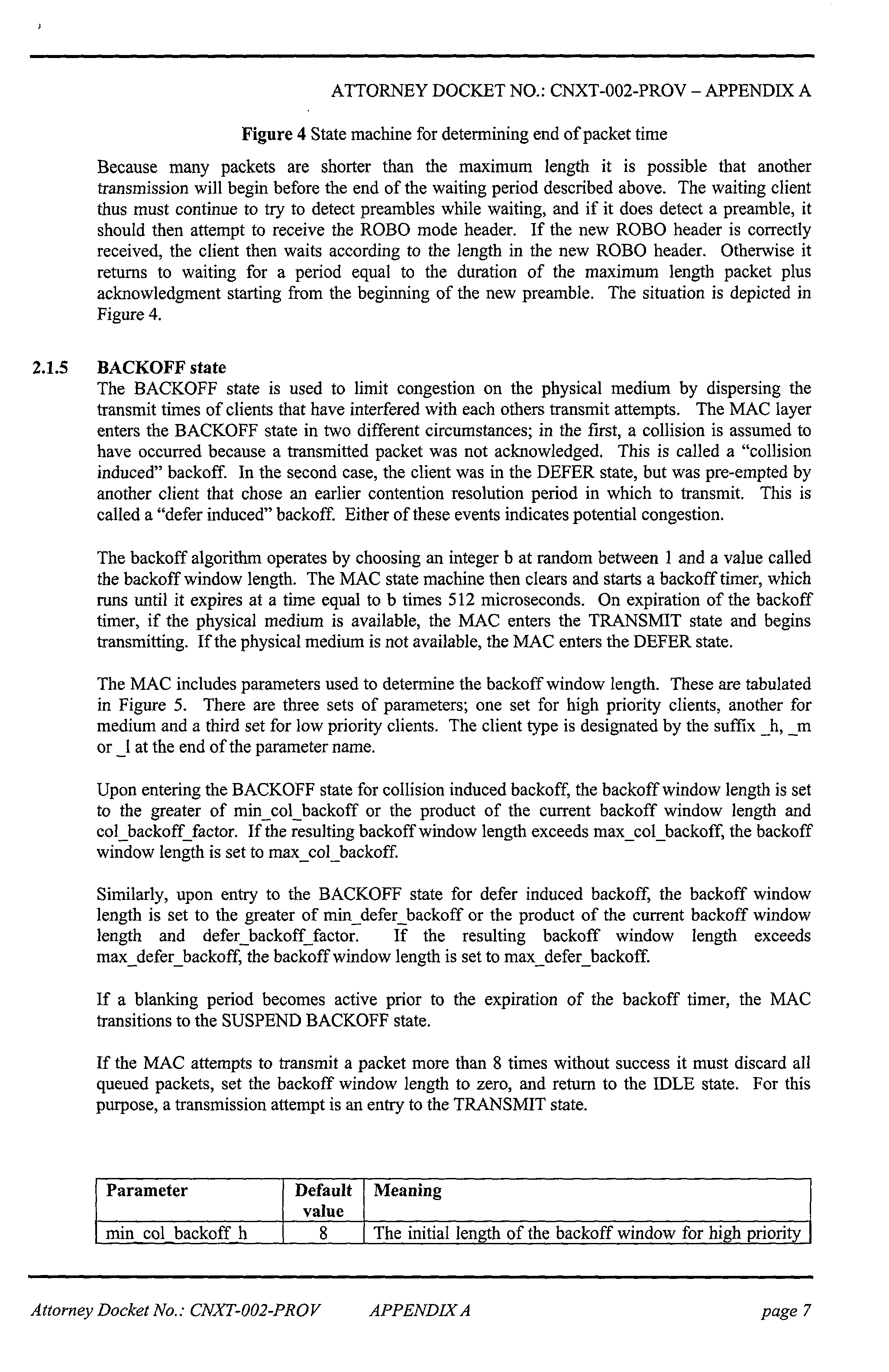


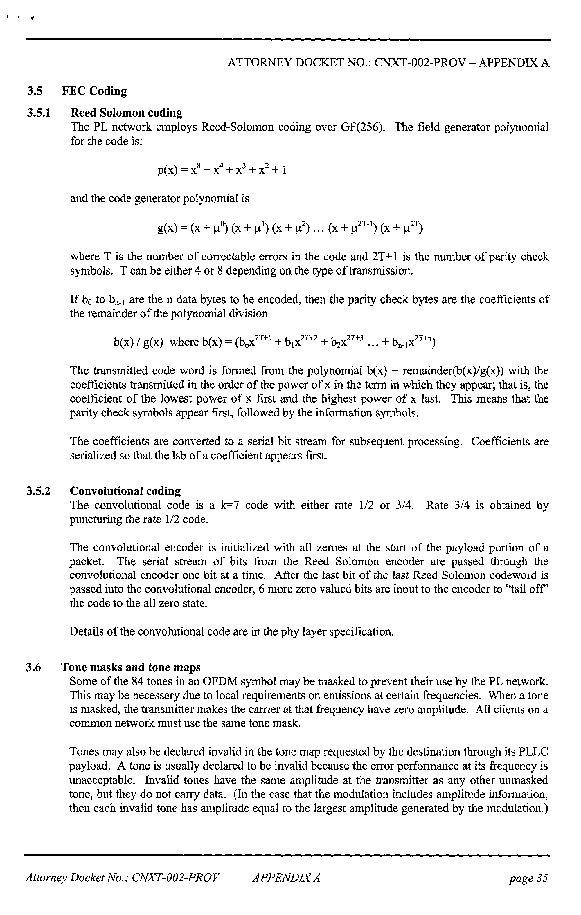

Claims (67)
Priority Applications (1)
| Application Number | Priority Date | Filing Date | Title |
|---|---|---|---|
| US09/876,454 US6854059B2 (en) | 2000-06-07 | 2001-06-06 | Method and apparatus for medium access control in powerline communication network systems |
Applications Claiming Priority (2)
| Application Number | Priority Date | Filing Date | Title |
|---|---|---|---|
| US21014800P | 2000-06-07 | 2000-06-07 | |
| US09/876,454 US6854059B2 (en) | 2000-06-07 | 2001-06-06 | Method and apparatus for medium access control in powerline communication network systems |
Publications (2)
| Publication Number | Publication Date |
|---|---|
| US20020048368A1 true US20020048368A1 (en) | 2002-04-25 |
| US6854059B2 US6854059B2 (en) | 2005-02-08 |
Family
ID=22781766
Family Applications (1)
| Application Number | Title | Priority Date | Filing Date |
|---|---|---|---|
| US09/876,454 Expired - Fee Related US6854059B2 (en) | 2000-06-07 | 2001-06-06 | Method and apparatus for medium access control in powerline communication network systems |
Country Status (6)
| Country | Link |
|---|---|
| US (1) | US6854059B2 (en) |
| EP (1) | EP1316170A2 (en) |
| JP (1) | JP4810051B2 (en) |
| AU (1) | AU2001262573A1 (en) |
| TW (1) | TW513869B (en) |
| WO (1) | WO2001095557A2 (en) |
Cited By (67)
| Publication number | Priority date | Publication date | Assignee | Title |
|---|---|---|---|---|
| US20010054953A1 (en) * | 2000-04-14 | 2001-12-27 | Kline Paul A. | Digital communications utilizing medium voltage power distribution lines |
| US20020097953A1 (en) * | 2000-12-15 | 2002-07-25 | Kline Paul A. | Interfacing fiber optic data with electrical power systems |
| US20020110310A1 (en) * | 2001-02-14 | 2002-08-15 | Kline Paul A. | Method and apparatus for providing inductive coupling and decoupling of high-frequency, high-bandwidth data signals directly on and off of a high voltage power line |
| US20020150249A1 (en) * | 2001-03-27 | 2002-10-17 | Hideki Ohkita | Communication apparatus |
| US20030063752A1 (en) * | 2001-09-26 | 2003-04-03 | General Instrument Corporation | Access control and key management system for streaming media |
| US20030169155A1 (en) * | 2000-04-14 | 2003-09-11 | Mollenkopf James Douglas | Power line communication system and method of using the same |
| US20030179080A1 (en) * | 2001-12-21 | 2003-09-25 | Mollenkopf James Douglas | Facilitating communication of data signals on electric power systems |
| US20030206535A1 (en) * | 2002-05-06 | 2003-11-06 | Extricom Ltd. | LAN with message interleaving |
| US20030206532A1 (en) * | 2002-05-06 | 2003-11-06 | Extricom Ltd. | Collaboration between wireless lan access points |
| US20030227373A1 (en) * | 2002-06-07 | 2003-12-11 | Heng Lou | Last leg utility grid high-speed data communication network having virtual local area network functionality |
| US20040001499A1 (en) * | 2002-06-26 | 2004-01-01 | Patella James Philip | Communication buffer scheme optimized for voip, QoS and data networking over a power line |
| US20040003338A1 (en) * | 2002-06-26 | 2004-01-01 | Kostoff Stanley J. | Powerline network flood control restriction |
| US20040001440A1 (en) * | 2002-06-26 | 2004-01-01 | Kostoff Stanley J. | Powerline network bridging congestion control |
| US20040003934A1 (en) * | 2002-06-24 | 2004-01-08 | Cope Leonard David | Power line coupling device and method of using the same |
| US20040110483A1 (en) * | 2002-12-10 | 2004-06-10 | Mollenkopf James Douglas | Power line communication sytem and method |
| US20040113756A1 (en) * | 2002-12-10 | 2004-06-17 | Mollenkopf James Douglas | Device and method for coupling with electrical distribution network infrastructure to provide communications |
| US20040113757A1 (en) * | 2002-12-10 | 2004-06-17 | White Melvin Joseph | Power line communication system and method of operating the same |
| US20040135676A1 (en) * | 2002-12-10 | 2004-07-15 | Berkman William H. | Power line communication system and method of operating the same |
| US20040156399A1 (en) * | 2002-08-07 | 2004-08-12 | Extricom Ltd. | Wireless LAN control over a wired network |
| US20040227621A1 (en) * | 2000-04-14 | 2004-11-18 | Cope Leonard D. | Power line communication apparatus and method of using the same |
| US20040227622A1 (en) * | 2003-05-13 | 2004-11-18 | Giannini Paul M. | Device and method for communicating data signals through multiple power line conductors |
| WO2004112273A1 (en) * | 2003-06-18 | 2004-12-23 | Diseño De Sistemas En Silicio, S.A. | Method enabling multiple communication nodes to access a transmission means on an electrical grid |
| US20050114489A1 (en) * | 2003-11-24 | 2005-05-26 | Yonge Lawrence W.Iii | Medium access control layer that encapsulates data from a plurality of received data units into a plurality of independently transmittable blocks |
| US20050111533A1 (en) * | 2003-10-15 | 2005-05-26 | Berkman William H. | Surface wave power line communications system and method |
| US20050169296A1 (en) * | 2004-02-03 | 2005-08-04 | Srinivas Katar | Temporary priority promotion for network communications in which access to a shared medium depends on a priority level |
| US20050168326A1 (en) * | 2002-12-10 | 2005-08-04 | Current Technologies, Llc | Power line repeater system and method |
| US20050198370A1 (en) * | 2004-02-01 | 2005-09-08 | Phonex Broadband Corporation | Method for creating, deleting, and maintaining logical networks |
| US20050195786A1 (en) * | 2002-08-07 | 2005-09-08 | Extricom Ltd. | Spatial reuse of frequency channels in a WLAN |
| US20050232275A1 (en) * | 2004-03-12 | 2005-10-20 | Stephens Adrian P | Legacy device fairness apparatus, systems, and methods |
| US20060002189A1 (en) * | 2004-06-30 | 2006-01-05 | Berkman William H | System and method for determining service availability and soliciting customers |
| US20060114925A1 (en) * | 2004-12-01 | 2006-06-01 | At&T Corp. | Interference control in a broadband powerline communication system |
| US20060171174A1 (en) * | 2001-02-14 | 2006-08-03 | Kline Paul A | Data communication over a power line |
| US20060198387A1 (en) * | 2005-03-03 | 2006-09-07 | Yonge Lawrence W Iii | Reserving time periods for communication on power line networks |
| US20060255930A1 (en) * | 2005-05-12 | 2006-11-16 | Berkman William H | Power line communications system and method |
| US20070002771A1 (en) * | 2005-06-21 | 2007-01-04 | Berkman William H | Power line communication rate limiting system and method |
| US20070037595A1 (en) * | 2005-08-11 | 2007-02-15 | Extricom Ltd. | Wlan operating on multiple adjacent bands |
| US20070050615A1 (en) * | 2005-09-01 | 2007-03-01 | Shugong Xu | System and method for automatic setup of a network device with secure network transmission of setup parameters using a standard remote control |
| US20070053352A1 (en) * | 2005-09-06 | 2007-03-08 | Corcoran Kevin F | Power line communications system with differentiated data services |
| US20070061575A1 (en) * | 2005-09-01 | 2007-03-15 | Bennett Richard T | System and method for automatic setup of a network device with secure network transmission of setup parameters |
| US20070091800A1 (en) * | 2005-10-21 | 2007-04-26 | Corcoran Kevin F | Power line communication voice over IP system and method |
| US20070218921A1 (en) * | 2006-03-20 | 2007-09-20 | Samsung Electronics Co., Ltd. | Method of joining a cell using a proxy coordinator, and a network therefor |
| US20070226779A1 (en) * | 2006-03-24 | 2007-09-27 | Matsushita Electric Industrial Co., Ltd. | Authentication relay apparatus, authentication relay system, integrated circuit, and authentication relay method |
| US20080068457A1 (en) * | 2006-09-19 | 2008-03-20 | Clemens Jonathan P | Hidden security techniques for wireless security devices |
| US20080112373A1 (en) * | 2006-11-14 | 2008-05-15 | Extricom Ltd. | Dynamic BSS allocation |
| US20080175265A1 (en) * | 2000-08-04 | 2008-07-24 | Yonge Lawrence W | Media Access Control Protocol With Priority And Contention-Free Intervals |
| US20080279126A1 (en) * | 2007-05-10 | 2008-11-13 | Srinivas Katar | Managing distributed access to a shared medium |
| US20090187499A1 (en) * | 2008-01-21 | 2009-07-23 | David Mulder | System, Method and Computer Program Product for Providing Demand Response Functionality |
| US20090187344A1 (en) * | 2008-01-19 | 2009-07-23 | Brancaccio Daniel S | System, Method, and Computer Program Product for Analyzing Power Grid Data |
| US20090187284A1 (en) * | 2008-01-21 | 2009-07-23 | Kreiss David G | System and Method for Providing Power Distribution System Information |
| US20090184835A1 (en) * | 2008-01-20 | 2009-07-23 | Deaver Sr Brian J | System, Device and Method For Providing Power Outage and Restoration Notification |
| US20090289637A1 (en) * | 2007-11-07 | 2009-11-26 | Radtke William O | System and Method for Determining the Impedance of a Medium Voltage Power Line |
| US20100017617A1 (en) * | 2008-07-21 | 2010-01-21 | Electronics And Telecommunications Research Institute | Radio frequency identification (rfid) security apparatus having security function and method thereof |
| US7715425B2 (en) | 2004-02-26 | 2010-05-11 | Atheros Communications, Inc. | Channel adaptation synchronized to periodically varying channel |
| US20100150172A1 (en) * | 2003-06-29 | 2010-06-17 | Main.Net Communications Ltd. | Dynamic power line bandwidth limit |
| US7822059B2 (en) | 2005-07-27 | 2010-10-26 | Atheros Communications, Inc. | Managing contention-free time allocations in a network |
| US8175190B2 (en) | 2005-07-27 | 2012-05-08 | Qualcomm Atheros, Inc. | Managing spectra of modulated signals in a communication network |
| US20120182955A1 (en) * | 2007-01-30 | 2012-07-19 | Broadcom Corporation | Multi-Network Shared Phy Layer |
| US20130290832A1 (en) * | 2007-03-06 | 2013-10-31 | Facebook, Inc. | Post-to-Post Profile Control |
| US8588844B2 (en) | 2010-11-04 | 2013-11-19 | Extricom Ltd. | MIMO search over multiple access points |
| US8660013B2 (en) | 2010-04-12 | 2014-02-25 | Qualcomm Incorporated | Detecting delimiters for low-overhead communication in a network |
| US8879700B2 (en) | 2005-10-12 | 2014-11-04 | Panasonic Corporation | Communication apparatus, integrated circuit, and communication method |
| US8891605B2 (en) | 2013-03-13 | 2014-11-18 | Qualcomm Incorporated | Variable line cycle adaptation for powerline communications |
| US20150078403A1 (en) * | 2004-05-06 | 2015-03-19 | At&T Intellectual Property Ii, L.P. | Outbound Interference Reduction in a Broadband Powerline System |
| WO2015130684A1 (en) * | 2014-02-25 | 2015-09-03 | Qualcomm Incorporated | Slotted message access protocol for powerline communication networks |
| US10203953B2 (en) | 2017-02-24 | 2019-02-12 | Microsoft Technology Licensing, Llc | Identification of duplicate function implementations |
| US20200145824A1 (en) * | 2018-11-05 | 2020-05-07 | Comcast Cable Communications, Llc | Localized Multi-Factor Network Authentication |
| CN117014143A (en) * | 2023-10-07 | 2023-11-07 | 北京数盾信息科技有限公司 | Key distribution method, system and equipment of load encryption gateway equipment |
Families Citing this family (64)
| Publication number | Priority date | Publication date | Assignee | Title |
|---|---|---|---|---|
| US6480510B1 (en) | 1998-07-28 | 2002-11-12 | Serconet Ltd. | Local area network of serial intelligent cells |
| US6549616B1 (en) | 2000-03-20 | 2003-04-15 | Serconet Ltd. | Telephone outlet for implementing a local area network over telephone lines and a local area network using such outlets |
| US6842459B1 (en) * | 2000-04-19 | 2005-01-11 | Serconet Ltd. | Network combining wired and non-wired segments |
| TWI454008B (en) * | 2011-01-04 | 2014-09-21 | Delta Electronics Inc | Power distribution unit and power management system employing the same |
| GB0124884D0 (en) * | 2001-03-20 | 2001-12-05 | Koninkl Philips Electronics Nv | Information system for travellers |
| US20020186125A1 (en) * | 2001-06-08 | 2002-12-12 | Li Victor Tzar Kuoi | System and method for providing high-speed communications over an electrical network |
| US20020186699A1 (en) * | 2001-06-08 | 2002-12-12 | Kwok Timothy Chung Hing | System and method for providing high-speed communications access over an electrical network |
| US7051264B2 (en) * | 2001-11-14 | 2006-05-23 | Monolithic System Technology, Inc. | Error correcting memory and method of operating same |
| CA2479628A1 (en) * | 2002-03-28 | 2003-10-09 | British Telecommunications Public Limited Company | Method and apparatus for network security |
| CN1672386A (en) * | 2002-07-29 | 2005-09-21 | 皇家飞利浦电子股份有限公司 | Security system for apparatuses in a network |
| US7761555B1 (en) * | 2002-08-06 | 2010-07-20 | Richard Anthony Bishel | Internet/intranet-connected AC electrical box |
| WO2004017529A2 (en) * | 2002-08-19 | 2004-02-26 | Arkados, Inc. | Method and system for maximizing data throughput rate in a power line communications system by modifying payload symbol length |
| US7529372B2 (en) * | 2002-09-25 | 2009-05-05 | Intellon Corporation | Method for setting an encryption key for logical network separation |
| IL152824A (en) | 2002-11-13 | 2012-05-31 | Mosaid Technologies Inc | Addressable outlet and a network using same |
| KR100505230B1 (en) * | 2002-12-10 | 2005-08-03 | 엘지전자 주식회사 | Home Network System and Home Appliance Reducing Method for the Same |
| JP4473504B2 (en) * | 2002-12-19 | 2010-06-02 | パナソニックシステムネットワークス株式会社 | Management device for controlling appliances by power line communication and control method thereof |
| US7046124B2 (en) * | 2003-01-21 | 2006-05-16 | Current Technologies, Llc | Power line coupling device and method of using the same |
| US7136936B2 (en) * | 2003-10-03 | 2006-11-14 | Asoka Usa Corporation | Method and system for virtual powerline local area networks |
| IL160417A (en) * | 2004-02-16 | 2011-04-28 | Mosaid Technologies Inc | Outlet add-on module |
| CN1922833B (en) * | 2004-02-24 | 2010-09-08 | 松下电器产业株式会社 | Terminal apparatus for enabling a plurality of different communication systems to coexist |
| KR100561749B1 (en) * | 2004-03-12 | 2006-04-04 | 주식회사 젤라인 | A power line communication based service addition type meter gateway and a casing structure thereof, a power line communication system and a method using the same |
| US7616762B2 (en) * | 2004-08-20 | 2009-11-10 | Sony Corporation | System and method for authenticating/registering network device in power line communication (PLC) |
| US7583645B2 (en) | 2004-09-01 | 2009-09-01 | Intel Corporation | Adaptive MAC architecture for wireless networks |
| US7873058B2 (en) | 2004-11-08 | 2011-01-18 | Mosaid Technologies Incorporated | Outlet with analog signal adapter, a method for use thereof and a network using said outlet |
| US7392456B2 (en) * | 2004-11-23 | 2008-06-24 | Mosys, Inc. | Predictive error correction code generation facilitating high-speed byte-write in a semiconductor memory |
| US7630401B2 (en) * | 2005-04-28 | 2009-12-08 | Sony Corporation | Bandwith management in a network |
| US7319717B2 (en) * | 2005-06-28 | 2008-01-15 | International Broadband Electric Communications, Inc. | Device and method for enabling communications signals using a medium voltage power line |
| US7414526B2 (en) * | 2005-06-28 | 2008-08-19 | International Broadband Communications, Inc. | Coupling of communications signals to a power line |
| US7522812B2 (en) | 2005-07-15 | 2009-04-21 | International Broadband Electric Communications, Inc. | Coupling of communications signals to a power line |
| US7667344B2 (en) * | 2005-07-15 | 2010-02-23 | International Broadband Electric Communications, Inc. | Coupling communications signals to underground power lines |
| US7778514B2 (en) * | 2005-07-15 | 2010-08-17 | International Broadband Electric Communications, Inc. | Coupling of communications signals to a power line |
| ES2706727T3 (en) | 2005-12-02 | 2019-04-01 | Irobot Corp | Robot system |
| KR101099808B1 (en) | 2005-12-02 | 2011-12-27 | 아이로보트 코퍼레이션 | Robot system |
| KR101209248B1 (en) * | 2006-02-16 | 2012-12-06 | 삼성전자주식회사 | Method of data communication between PLC stations belonging to different PLC cells and apparatus therefor |
| KR100750171B1 (en) | 2006-03-14 | 2007-08-21 | 삼성전자주식회사 | Method of distributing gid in plc network, method of receiving gid in plc network, apparatus for authorization in plc network, and plc device |
| US7876849B2 (en) * | 2006-05-25 | 2011-01-25 | Viasat, Inc. | Data transmission method and apparatus using networked receivers having spatial diversity |
| US20080056338A1 (en) * | 2006-08-28 | 2008-03-06 | David Stanley Yaney | Power Line Communication Device and Method with Frequency Shifted Modem |
| US20090125351A1 (en) * | 2007-11-08 | 2009-05-14 | Davis Jr Robert G | System and Method for Establishing Communications with an Electronic Meter |
| US8234363B1 (en) | 2009-09-18 | 2012-07-31 | Kuo-Hua Kuo | Dynamic object management protocol |
| JP5591829B2 (en) * | 2009-12-28 | 2014-09-17 | 富士通株式会社 | Communication method and communication apparatus |
| US8755946B2 (en) | 2011-02-22 | 2014-06-17 | Asoka Usa Corporation | Method and apparatus for using PLC-based sensor units for communication and streaming media delivery, and for monitoring and control of power usage of connected appliances |
| US8364326B2 (en) * | 2011-02-22 | 2013-01-29 | Asoka Usa Corporation | Set of sensor units for communication enabled for streaming media delivery with monitoring and control of power usage of connected appliances |
| US9257842B2 (en) | 2011-02-22 | 2016-02-09 | Asoka Usa Corporation | Set-top-box having a built-in master node that provides an external interface for communication and control in a power-line-based residential communication system |
| US8644166B2 (en) | 2011-06-03 | 2014-02-04 | Asoka Usa Corporation | Sensor having an integrated Zigbee® device for communication with Zigbee® enabled appliances to control and monitor Zigbee® enabled appliances |
| US9736789B2 (en) | 2011-02-22 | 2017-08-15 | Asoka Usa Corporation | Power line communication-based local hotspot with wireless power control capability |
| KR101459255B1 (en) * | 2011-03-14 | 2014-11-07 | 퀄컴 인코포레이티드 | Hybrid networking master passphrase |
| US8930700B2 (en) * | 2012-12-12 | 2015-01-06 | Richard J. Wielopolski | Remote device secure data file storage system and method |
| WO2015038120A1 (en) | 2013-09-12 | 2015-03-19 | Empire Technology Development Llc | Circuit switch pre-reservation in an on-chip network |
| US9379888B2 (en) | 2013-12-06 | 2016-06-28 | Qualcomm Incorporated | Powerline communication network analyzer |
| US10686914B2 (en) * | 2014-11-04 | 2020-06-16 | Texas Instruments Incorporated | Automatic selection of MAC protocol to support multiple prime PLC standards |
| US10891076B1 (en) | 2016-12-06 | 2021-01-12 | Gsi Technology, Inc. | Results processing circuits and methods associated with computational memory cells |
| US10847213B1 (en) | 2016-12-06 | 2020-11-24 | Gsi Technology, Inc. | Write data processing circuits and methods associated with computational memory cells |
| US10854284B1 (en) | 2016-12-06 | 2020-12-01 | Gsi Technology, Inc. | Computational memory cell and processing array device with ratioless write port |
| US10860320B1 (en) | 2016-12-06 | 2020-12-08 | Gsi Technology, Inc. | Orthogonal data transposition system and method during data transfers to/from a processing array |
| US10249362B2 (en) | 2016-12-06 | 2019-04-02 | Gsi Technology, Inc. | Computational memory cell and processing array device using the memory cells for XOR and XNOR computations |
| US10847212B1 (en) | 2016-12-06 | 2020-11-24 | Gsi Technology, Inc. | Read and write data processing circuits and methods associated with computational memory cells using two read multiplexers |
| US10770133B1 (en) | 2016-12-06 | 2020-09-08 | Gsi Technology, Inc. | Read and write data processing circuits and methods associated with computational memory cells that provides write inhibits and read bit line pre-charge inhibits |
| US10777262B1 (en) | 2016-12-06 | 2020-09-15 | Gsi Technology, Inc. | Read data processing circuits and methods associated memory cells |
| US10943648B1 (en) | 2016-12-06 | 2021-03-09 | Gsi Technology, Inc. | Ultra low VDD memory cell with ratioless write port |
| US11227653B1 (en) | 2016-12-06 | 2022-01-18 | Gsi Technology, Inc. | Storage array circuits and methods for computational memory cells |
| US10725777B2 (en) | 2016-12-06 | 2020-07-28 | Gsi Technology, Inc. | Computational memory cell and processing array device using memory cells |
| US10958272B2 (en) | 2019-06-18 | 2021-03-23 | Gsi Technology, Inc. | Computational memory cell and processing array device using complementary exclusive or memory cells |
| US10877731B1 (en) | 2019-06-18 | 2020-12-29 | Gsi Technology, Inc. | Processing array device that performs one cycle full adder operation and bit line read/write logic features |
| US10930341B1 (en) | 2019-06-18 | 2021-02-23 | Gsi Technology, Inc. | Processing array device that performs one cycle full adder operation and bit line read/write logic features |
Citations (11)
| Publication number | Priority date | Publication date | Assignee | Title |
|---|---|---|---|---|
| US5459462A (en) * | 1993-12-09 | 1995-10-17 | Onspec Electronic, Inc. | Keyboard controller state machine |
| US5835592A (en) * | 1995-06-01 | 1998-11-10 | Chang; Chung Nan | Secure, swift cryptographic key exchange |
| US5857024A (en) * | 1995-10-02 | 1999-01-05 | International Business Machines Corporation | IC card and authentication method for information processing apparatus |
| US6130896A (en) * | 1997-10-20 | 2000-10-10 | Intel Corporation | Wireless LAN segments with point coordination |
| US6373950B1 (en) * | 1996-06-17 | 2002-04-16 | Hewlett-Packard Company | System, method and article of manufacture for transmitting messages within messages utilizing an extensible, flexible architecture |
| US20030050737A1 (en) * | 2001-09-10 | 2003-03-13 | Robert Osann | Energy-smart home system |
| US20030068033A1 (en) * | 2001-10-10 | 2003-04-10 | Kiko Frederick J. | Telecommunications gateway and method |
| US20030090368A1 (en) * | 1999-12-30 | 2003-05-15 | Hans-Dieter Ide | Device and method for converting a two-directional so data stream for transmission via a low-voltage power network |
| US20030103521A1 (en) * | 2001-06-18 | 2003-06-05 | Itran Communications Ltd. | Channel access method for powerline carrier based media access control protocol |
| US20030133473A1 (en) * | 2001-08-04 | 2003-07-17 | Manis Constantine N. | Power line communication system |
| US20040075535A1 (en) * | 1999-12-02 | 2004-04-22 | Propp Michael B | Power line communication network |
Family Cites Families (10)
| Publication number | Priority date | Publication date | Assignee | Title |
|---|---|---|---|---|
| JPH01269975A (en) * | 1988-04-21 | 1989-10-27 | Nec Corp | Simple type data ciphering system |
| GB8920261D0 (en) * | 1989-09-07 | 1989-10-18 | Verran Electronics Limited | Computer communications system |
| JP3308561B2 (en) * | 1990-11-14 | 2002-07-29 | 株式会社東芝 | E-mail communication method and sender terminal |
| WO1992016895A1 (en) * | 1991-03-18 | 1992-10-01 | Echelon Corporation | Networked variables |
| US5631906A (en) * | 1993-03-11 | 1997-05-20 | Liu; Zheng | Medium access control protocol for single bus fair access local area network |
| US5453987A (en) * | 1994-02-15 | 1995-09-26 | The Mitre Corporation | Random access protocol for multi-media networks |
| US5680458A (en) * | 1995-11-14 | 1997-10-21 | Microsoft Corporation | Root key compromise recovery |
| DE19716011A1 (en) * | 1997-04-17 | 1998-10-22 | Abb Research Ltd | Method and device for transmitting information via power supply lines |
| JP2000115036A (en) * | 1998-10-08 | 2000-04-21 | Maitakku:Kk | Data transmitting device |
| US6308282B1 (en) * | 1998-11-10 | 2001-10-23 | Honeywell International Inc. | Apparatus and methods for providing fault tolerance of networks and network interface cards |
-
2001
- 2001-06-06 WO PCT/IB2001/000988 patent/WO2001095557A2/en not_active Application Discontinuation
- 2001-06-06 AU AU2001262573A patent/AU2001262573A1/en not_active Abandoned
- 2001-06-06 EP EP01936706A patent/EP1316170A2/en not_active Withdrawn
- 2001-06-06 US US09/876,454 patent/US6854059B2/en not_active Expired - Fee Related
- 2001-06-06 JP JP2002502974A patent/JP4810051B2/en not_active Expired - Fee Related
- 2001-08-01 TW TW090113820A patent/TW513869B/en not_active IP Right Cessation
Patent Citations (11)
| Publication number | Priority date | Publication date | Assignee | Title |
|---|---|---|---|---|
| US5459462A (en) * | 1993-12-09 | 1995-10-17 | Onspec Electronic, Inc. | Keyboard controller state machine |
| US5835592A (en) * | 1995-06-01 | 1998-11-10 | Chang; Chung Nan | Secure, swift cryptographic key exchange |
| US5857024A (en) * | 1995-10-02 | 1999-01-05 | International Business Machines Corporation | IC card and authentication method for information processing apparatus |
| US6373950B1 (en) * | 1996-06-17 | 2002-04-16 | Hewlett-Packard Company | System, method and article of manufacture for transmitting messages within messages utilizing an extensible, flexible architecture |
| US6130896A (en) * | 1997-10-20 | 2000-10-10 | Intel Corporation | Wireless LAN segments with point coordination |
| US20040075535A1 (en) * | 1999-12-02 | 2004-04-22 | Propp Michael B | Power line communication network |
| US20030090368A1 (en) * | 1999-12-30 | 2003-05-15 | Hans-Dieter Ide | Device and method for converting a two-directional so data stream for transmission via a low-voltage power network |
| US20030103521A1 (en) * | 2001-06-18 | 2003-06-05 | Itran Communications Ltd. | Channel access method for powerline carrier based media access control protocol |
| US20030133473A1 (en) * | 2001-08-04 | 2003-07-17 | Manis Constantine N. | Power line communication system |
| US20030050737A1 (en) * | 2001-09-10 | 2003-03-13 | Robert Osann | Energy-smart home system |
| US20030068033A1 (en) * | 2001-10-10 | 2003-04-10 | Kiko Frederick J. | Telecommunications gateway and method |
Cited By (135)
| Publication number | Priority date | Publication date | Assignee | Title |
|---|---|---|---|---|
| US20050206507A1 (en) * | 2000-04-14 | 2005-09-22 | Kline Paul A | Power line communication system and method |
| US20010054953A1 (en) * | 2000-04-14 | 2001-12-27 | Kline Paul A. | Digital communications utilizing medium voltage power distribution lines |
| US20040227621A1 (en) * | 2000-04-14 | 2004-11-18 | Cope Leonard D. | Power line communication apparatus and method of using the same |
| US20030169155A1 (en) * | 2000-04-14 | 2003-09-11 | Mollenkopf James Douglas | Power line communication system and method of using the same |
| US7916746B2 (en) | 2000-08-04 | 2011-03-29 | Atheros Communications, Inc. | Media access control protocol with priority and contention-free intervals |
| US20080175265A1 (en) * | 2000-08-04 | 2008-07-24 | Yonge Lawrence W | Media Access Control Protocol With Priority And Contention-Free Intervals |
| US20020097953A1 (en) * | 2000-12-15 | 2002-07-25 | Kline Paul A. | Interfacing fiber optic data with electrical power systems |
| US20030190110A1 (en) * | 2001-02-14 | 2003-10-09 | Kline Paul A. | Method and apparatus for providing inductive coupling and decoupling of high-frequency, high-bandwidth data signals directly on and off of a high voltage power line |
| US20060171174A1 (en) * | 2001-02-14 | 2006-08-03 | Kline Paul A | Data communication over a power line |
| US20020110310A1 (en) * | 2001-02-14 | 2002-08-15 | Kline Paul A. | Method and apparatus for providing inductive coupling and decoupling of high-frequency, high-bandwidth data signals directly on and off of a high voltage power line |
| US20020150249A1 (en) * | 2001-03-27 | 2002-10-17 | Hideki Ohkita | Communication apparatus |
| US20100102987A1 (en) * | 2001-05-18 | 2010-04-29 | Heng Lou | Power Line Communication Device having Virtual Local Area Network Functionality |
| US20030063752A1 (en) * | 2001-09-26 | 2003-04-03 | General Instrument Corporation | Access control and key management system for streaming media |
| US8255989B2 (en) * | 2001-09-26 | 2012-08-28 | General Instrument Corporation | Access control and key management system for streaming media |
| US20030179080A1 (en) * | 2001-12-21 | 2003-09-25 | Mollenkopf James Douglas | Facilitating communication of data signals on electric power systems |
| US7319688B2 (en) * | 2002-05-06 | 2008-01-15 | Extricom Ltd. | LAN with message interleaving |
| US20030206535A1 (en) * | 2002-05-06 | 2003-11-06 | Extricom Ltd. | LAN with message interleaving |
| US20030206532A1 (en) * | 2002-05-06 | 2003-11-06 | Extricom Ltd. | Collaboration between wireless lan access points |
| US20070201494A1 (en) * | 2002-06-07 | 2007-08-30 | Heng Lou | Last Leg Utility Grid High-Speed Data Communication Network Having Virtual Local Area Network Functionality |
| US7664117B2 (en) | 2002-06-07 | 2010-02-16 | Current Grid, Llc | Last leg utility grid high-speed data communication network having virtual local area network functionality |
| US7173935B2 (en) | 2002-06-07 | 2007-02-06 | Current Grid, Llc | Last leg utility grid high-speed data communication network having virtual local area network functionality |
| US20030227373A1 (en) * | 2002-06-07 | 2003-12-11 | Heng Lou | Last leg utility grid high-speed data communication network having virtual local area network functionality |
| US20040003934A1 (en) * | 2002-06-24 | 2004-01-08 | Cope Leonard David | Power line coupling device and method of using the same |
| US20040001440A1 (en) * | 2002-06-26 | 2004-01-01 | Kostoff Stanley J. | Powerline network bridging congestion control |
| US7826466B2 (en) | 2002-06-26 | 2010-11-02 | Atheros Communications, Inc. | Communication buffer scheme optimized for VoIP, QoS and data networking over a power line |
| US20040003338A1 (en) * | 2002-06-26 | 2004-01-01 | Kostoff Stanley J. | Powerline network flood control restriction |
| US8149703B2 (en) | 2002-06-26 | 2012-04-03 | Qualcomm Atheros, Inc. | Powerline network bridging congestion control |
| US20040001499A1 (en) * | 2002-06-26 | 2004-01-01 | Patella James Philip | Communication buffer scheme optimized for voip, QoS and data networking over a power line |
| US7797016B2 (en) | 2002-08-07 | 2010-09-14 | Extricom Ltd. | Wireless LAN with central management of access points |
| US20040156399A1 (en) * | 2002-08-07 | 2004-08-12 | Extricom Ltd. | Wireless LAN control over a wired network |
| US20050195786A1 (en) * | 2002-08-07 | 2005-09-08 | Extricom Ltd. | Spatial reuse of frequency channels in a WLAN |
| US20040063455A1 (en) * | 2002-08-07 | 2004-04-01 | Extricom Ltd. | Wireless LAN with central management of access points |
| US7697549B2 (en) | 2002-08-07 | 2010-04-13 | Extricom Ltd. | Wireless LAN control over a wired network |
| US20090134996A1 (en) * | 2002-12-10 | 2009-05-28 | White Ii Melvin Joseph | Power Line Communication System and Method of Operating the Same |
| US20040113757A1 (en) * | 2002-12-10 | 2004-06-17 | White Melvin Joseph | Power line communication system and method of operating the same |
| US20060038662A1 (en) * | 2002-12-10 | 2006-02-23 | White Melvin J Ii | Power line communication system and method of operating the same |
| US20050168326A1 (en) * | 2002-12-10 | 2005-08-04 | Current Technologies, Llc | Power line repeater system and method |
| US7224272B2 (en) | 2002-12-10 | 2007-05-29 | Current Technologies, Llc | Power line repeater system and method |
| US20040113756A1 (en) * | 2002-12-10 | 2004-06-17 | Mollenkopf James Douglas | Device and method for coupling with electrical distribution network infrastructure to provide communications |
| US7466225B2 (en) | 2002-12-10 | 2008-12-16 | Current Technologies, Llc | Power line communication system and method of operating the same |
| US7701325B2 (en) | 2002-12-10 | 2010-04-20 | Current Technologies, Llc | Power line communication apparatus and method of using the same |
| US20040135676A1 (en) * | 2002-12-10 | 2004-07-15 | Berkman William H. | Power line communication system and method of operating the same |
| US8198999B2 (en) | 2002-12-10 | 2012-06-12 | Current Technologies, Llc | Power line communication system and method of operating the same |
| US20040110483A1 (en) * | 2002-12-10 | 2004-06-10 | Mollenkopf James Douglas | Power line communication sytem and method |
| US20040227622A1 (en) * | 2003-05-13 | 2004-11-18 | Giannini Paul M. | Device and method for communicating data signals through multiple power line conductors |
| EA008853B1 (en) * | 2003-06-18 | 2007-08-31 | Дисеньо Де Системас Эн Силисио, С.А. | Method enabling multiple communication nodes to access a transmission means on an electrical grid |
| ES2221803A1 (en) * | 2003-06-18 | 2005-01-01 | Diseño De Sistemas En Silicio, S.A. | Method enabling multiple communication nodes to access a transmission means on an electrical grid |
| WO2004112273A1 (en) * | 2003-06-18 | 2004-12-23 | Diseño De Sistemas En Silicio, S.A. | Method enabling multiple communication nodes to access a transmission means on an electrical grid |
| US20100150172A1 (en) * | 2003-06-29 | 2010-06-17 | Main.Net Communications Ltd. | Dynamic power line bandwidth limit |
| US20050111533A1 (en) * | 2003-10-15 | 2005-05-26 | Berkman William H. | Surface wave power line communications system and method |
| US7280033B2 (en) | 2003-10-15 | 2007-10-09 | Current Technologies, Llc | Surface wave power line communications system and method |
| US20050114489A1 (en) * | 2003-11-24 | 2005-05-26 | Yonge Lawrence W.Iii | Medium access control layer that encapsulates data from a plurality of received data units into a plurality of independently transmittable blocks |
| US9013989B2 (en) | 2003-11-24 | 2015-04-21 | Qualcomm Incorporated | Medium access control layer that encapsulates data from a plurality of received data units into a plurality of independently transmittable blocks |
| US8654635B2 (en) | 2003-11-24 | 2014-02-18 | Qualcomm Incorporated | Medium access control layer that encapsulates data from a plurality of received data units into a plurality of independently transmittable blocks |
| US8090857B2 (en) | 2003-11-24 | 2012-01-03 | Qualcomm Atheros, Inc. | Medium access control layer that encapsulates data from a plurality of received data units into a plurality of independently transmittable blocks |
| US20050198370A1 (en) * | 2004-02-01 | 2005-09-08 | Phonex Broadband Corporation | Method for creating, deleting, and maintaining logical networks |
| US20050169296A1 (en) * | 2004-02-03 | 2005-08-04 | Srinivas Katar | Temporary priority promotion for network communications in which access to a shared medium depends on a priority level |
| US7660327B2 (en) | 2004-02-03 | 2010-02-09 | Atheros Communications, Inc. | Temporary priority promotion for network communications in which access to a shared medium depends on a priority level |
| US7715425B2 (en) | 2004-02-26 | 2010-05-11 | Atheros Communications, Inc. | Channel adaptation synchronized to periodically varying channel |
| US20050232275A1 (en) * | 2004-03-12 | 2005-10-20 | Stephens Adrian P | Legacy device fairness apparatus, systems, and methods |
| US10700737B2 (en) | 2004-05-06 | 2020-06-30 | At&T Intellectual Property Ii, L.P. | Outbound interference reduction in a broadband powerline system |
| US9577706B2 (en) * | 2004-05-06 | 2017-02-21 | At&T Intellectual Property Ii, L.P. | Outbound interference reduction in a broadband powerline system |
| US20150078403A1 (en) * | 2004-05-06 | 2015-03-19 | At&T Intellectual Property Ii, L.P. | Outbound Interference Reduction in a Broadband Powerline System |
| US10312965B2 (en) | 2004-05-06 | 2019-06-04 | At&T Intellectual Property Ii, L.P. | Outbound interference reduction in a broadband powerline system |
| US9887734B2 (en) | 2004-05-06 | 2018-02-06 | At&T Intellectual Property Ii, L.P. | Outbound interference reduction in a broadband powerline system |
| WO2006011964A1 (en) * | 2004-06-28 | 2006-02-02 | Intel Corporation | Legacy device fairness apparatus, systems, and methods in mixed-generation networks |
| US20060002189A1 (en) * | 2004-06-30 | 2006-01-05 | Berkman William H | System and method for determining service availability and soliciting customers |
| US9172429B2 (en) * | 2004-12-01 | 2015-10-27 | At&T Intellectual Property Ii, L.P. | Interference control in a broadband powerline communication system |
| US10263666B2 (en) | 2004-12-01 | 2019-04-16 | At&T Intellectual Property Ii, L.P. | Interference control in a broadband powerline communication system |
| US9780835B2 (en) | 2004-12-01 | 2017-10-03 | At&T Intellectual Property Ii, L.P. | Interference control in a broadband powerline communication system |
| US20060114925A1 (en) * | 2004-12-01 | 2006-06-01 | At&T Corp. | Interference control in a broadband powerline communication system |
| US20060198387A1 (en) * | 2005-03-03 | 2006-09-07 | Yonge Lawrence W Iii | Reserving time periods for communication on power line networks |
| US20060255930A1 (en) * | 2005-05-12 | 2006-11-16 | Berkman William H | Power line communications system and method |
| US7558206B2 (en) | 2005-06-21 | 2009-07-07 | Current Technologies, Llc | Power line communication rate limiting system and method |
| US20070002771A1 (en) * | 2005-06-21 | 2007-01-04 | Berkman William H | Power line communication rate limiting system and method |
| US7822059B2 (en) | 2005-07-27 | 2010-10-26 | Atheros Communications, Inc. | Managing contention-free time allocations in a network |
| US8416887B2 (en) | 2005-07-27 | 2013-04-09 | Qualcomm Atheros, Inc | Managing spectra of modulated signals in a communication network |
| US8175190B2 (en) | 2005-07-27 | 2012-05-08 | Qualcomm Atheros, Inc. | Managing spectra of modulated signals in a communication network |
| US7813738B2 (en) | 2005-08-11 | 2010-10-12 | Extricom Ltd. | WLAN operating on multiple adjacent bands |
| US20070037595A1 (en) * | 2005-08-11 | 2007-02-15 | Extricom Ltd. | Wlan operating on multiple adjacent bands |
| US7609837B2 (en) * | 2005-09-01 | 2009-10-27 | Sharp Laboratories Of America, Inc. | System and method for automatic setup of a network device with secure network transmission of setup parameters |
| US20070061575A1 (en) * | 2005-09-01 | 2007-03-15 | Bennett Richard T | System and method for automatic setup of a network device with secure network transmission of setup parameters |
| US20070050615A1 (en) * | 2005-09-01 | 2007-03-01 | Shugong Xu | System and method for automatic setup of a network device with secure network transmission of setup parameters using a standard remote control |
| US7916869B2 (en) * | 2005-09-01 | 2011-03-29 | Sharp Laboratories Of America, Inc. | System and method for automatic setup of a network device with secure network transmission of setup parameters using a standard remote control |
| US7675897B2 (en) | 2005-09-06 | 2010-03-09 | Current Technologies, Llc | Power line communications system with differentiated data services |
| US20070053352A1 (en) * | 2005-09-06 | 2007-03-08 | Corcoran Kevin F | Power line communications system with differentiated data services |
| US8879700B2 (en) | 2005-10-12 | 2014-11-04 | Panasonic Corporation | Communication apparatus, integrated circuit, and communication method |
| US9419756B2 (en) | 2005-10-12 | 2016-08-16 | Panasonic Corporation | Communication apparatus, integrated circuit, and communication method |
| US20070091800A1 (en) * | 2005-10-21 | 2007-04-26 | Corcoran Kevin F | Power line communication voice over IP system and method |
| US7856007B2 (en) | 2005-10-21 | 2010-12-21 | Current Technologies, Llc | Power line communication voice over IP system and method |
| US8130783B2 (en) * | 2006-03-20 | 2012-03-06 | Samsung Electronics Co., Ltd. | Method of joining a cell using a proxy coordinator, and a network therefor |
| US20070218921A1 (en) * | 2006-03-20 | 2007-09-20 | Samsung Electronics Co., Ltd. | Method of joining a cell using a proxy coordinator, and a network therefor |
| CN101411113A (en) * | 2006-03-24 | 2009-04-15 | 松下电器产业株式会社 | Authentication relay apparatus, authentication relay system, integrated circuit, and authentication relay method |
| US20070226779A1 (en) * | 2006-03-24 | 2007-09-27 | Matsushita Electric Industrial Co., Ltd. | Authentication relay apparatus, authentication relay system, integrated circuit, and authentication relay method |
| US8471904B2 (en) * | 2006-09-19 | 2013-06-25 | Intel Corporation | Hidden security techniques for wireless security devices |
| US20080068457A1 (en) * | 2006-09-19 | 2008-03-20 | Clemens Jonathan P | Hidden security techniques for wireless security devices |
| US20080112373A1 (en) * | 2006-11-14 | 2008-05-15 | Extricom Ltd. | Dynamic BSS allocation |
| US20120182955A1 (en) * | 2007-01-30 | 2012-07-19 | Broadcom Corporation | Multi-Network Shared Phy Layer |
| US8705564B2 (en) * | 2007-01-30 | 2014-04-22 | Broadcom Corporation | Multi-network shared PHY layer |
| US9798705B2 (en) | 2007-03-06 | 2017-10-24 | Facebook, Inc. | Multimedia aggregation in an online social network |
| US10592594B2 (en) | 2007-03-06 | 2020-03-17 | Facebook, Inc. | Selecting popular content on online social networks |
| US10140264B2 (en) | 2007-03-06 | 2018-11-27 | Facebook, Inc. | Multimedia aggregation in an online social network |
| US20130290832A1 (en) * | 2007-03-06 | 2013-10-31 | Facebook, Inc. | Post-to-Post Profile Control |
| US9817797B2 (en) | 2007-03-06 | 2017-11-14 | Facebook, Inc. | Multimedia aggregation in an online social network |
| US10013399B2 (en) * | 2007-03-06 | 2018-07-03 | Facebook, Inc. | Post-to-post profile control |
| US9959253B2 (en) | 2007-03-06 | 2018-05-01 | Facebook, Inc. | Multimedia aggregation in an online social network |
| US8493995B2 (en) | 2007-05-10 | 2013-07-23 | Qualcomm Incorporated | Managing distributed access to a shared medium |
| US20080279126A1 (en) * | 2007-05-10 | 2008-11-13 | Srinivas Katar | Managing distributed access to a shared medium |
| US9413688B2 (en) | 2007-05-10 | 2016-08-09 | Qualcomm Incorporated | Managing distributed access to a shared medium |
| US20090289637A1 (en) * | 2007-11-07 | 2009-11-26 | Radtke William O | System and Method for Determining the Impedance of a Medium Voltage Power Line |
| US20090187344A1 (en) * | 2008-01-19 | 2009-07-23 | Brancaccio Daniel S | System, Method, and Computer Program Product for Analyzing Power Grid Data |
| US7965195B2 (en) | 2008-01-20 | 2011-06-21 | Current Technologies, Llc | System, device and method for providing power outage and restoration notification |
| US20090184835A1 (en) * | 2008-01-20 | 2009-07-23 | Deaver Sr Brian J | System, Device and Method For Providing Power Outage and Restoration Notification |
| US20090187284A1 (en) * | 2008-01-21 | 2009-07-23 | Kreiss David G | System and Method for Providing Power Distribution System Information |
| US8285500B2 (en) | 2008-01-21 | 2012-10-09 | Current Communications Services, Llc | System and method for providing power distribution system information |
| US20090187499A1 (en) * | 2008-01-21 | 2009-07-23 | David Mulder | System, Method and Computer Program Product for Providing Demand Response Functionality |
| US8000913B2 (en) | 2008-01-21 | 2011-08-16 | Current Communications Services, Llc | System and method for providing power distribution system information |
| US8290727B2 (en) | 2008-01-21 | 2012-10-16 | Current Communications Services, Llc | System and method for providing power distribution system information |
| US8280656B2 (en) | 2008-01-21 | 2012-10-02 | Current Communications Services, Llc | System and method for providing power distribution system information |
| US8607333B2 (en) * | 2008-07-21 | 2013-12-10 | Electronics And Telecommunications Research Institute | Radio frequency identification (RFID) security apparatus having security function and method thereof |
| US20100017617A1 (en) * | 2008-07-21 | 2010-01-21 | Electronics And Telecommunications Research Institute | Radio frequency identification (rfid) security apparatus having security function and method thereof |
| US9295100B2 (en) | 2010-04-12 | 2016-03-22 | Qualcomm Incorporated | Delayed acknowledgements for low-overhead communication in a network |
| US8693558B2 (en) | 2010-04-12 | 2014-04-08 | Qualcomm Incorporated | Providing delimiters for low-overhead communication in a network |
| US9001909B2 (en) | 2010-04-12 | 2015-04-07 | Qualcomm Incorporated | Channel estimation for low-overhead communication in a network |
| US9326316B2 (en) | 2010-04-12 | 2016-04-26 | Qualcomm Incorporated | Repeating for low-overhead communication in a network |
| US9326317B2 (en) | 2010-04-12 | 2016-04-26 | Qualcomm Incorporated | Detecting delimiters for low-overhead communication in a network |
| US8781016B2 (en) | 2010-04-12 | 2014-07-15 | Qualcomm Incorporated | Channel estimation for low-overhead communication in a network |
| US8660013B2 (en) | 2010-04-12 | 2014-02-25 | Qualcomm Incorporated | Detecting delimiters for low-overhead communication in a network |
| US8588844B2 (en) | 2010-11-04 | 2013-11-19 | Extricom Ltd. | MIMO search over multiple access points |
| US8891605B2 (en) | 2013-03-13 | 2014-11-18 | Qualcomm Incorporated | Variable line cycle adaptation for powerline communications |
| WO2015130684A1 (en) * | 2014-02-25 | 2015-09-03 | Qualcomm Incorporated | Slotted message access protocol for powerline communication networks |
| US9762496B2 (en) | 2014-02-25 | 2017-09-12 | Qualcomm Incorporated | Slotted message access protocol for powerline communication networks |
| US10203953B2 (en) | 2017-02-24 | 2019-02-12 | Microsoft Technology Licensing, Llc | Identification of duplicate function implementations |
| US20200145824A1 (en) * | 2018-11-05 | 2020-05-07 | Comcast Cable Communications, Llc | Localized Multi-Factor Network Authentication |
| CN117014143A (en) * | 2023-10-07 | 2023-11-07 | 北京数盾信息科技有限公司 | Key distribution method, system and equipment of load encryption gateway equipment |
Also Published As
| Publication number | Publication date |
|---|---|
| WO2001095557A2 (en) | 2001-12-13 |
| AU2001262573A1 (en) | 2001-12-17 |
| WO2001095557A3 (en) | 2003-03-20 |
| EP1316170A2 (en) | 2003-06-04 |
| TW513869B (en) | 2002-12-11 |
| US6854059B2 (en) | 2005-02-08 |
| JP2004515090A (en) | 2004-05-20 |
| JP4810051B2 (en) | 2011-11-09 |
Similar Documents
| Publication | Publication Date | Title |
|---|---|---|
| US6854059B2 (en) | Method and apparatus for medium access control in powerline communication network systems | |
| Lee et al. | HomePlug 1.0 powerline communication LANs—protocol description and performance results | |
| KR101269036B1 (en) | Bandwidth management in a powerline network | |
| Eklund et al. | IEEE standard 802.16: a technical overview of the WirelessMAN/sup TM/air interface for broadband wireless access | |
| CN100382519C (en) | Method and association for making the only connection in multi-node network to adapt the highest data rate | |
| US8891544B1 (en) | Multimedia over coaxial cable access protocol | |
| CN1454419B (en) | Method to support contention-free intervals and QoS in a CSMA network | |
| US8498294B1 (en) | Multimedia over coaxial cable access protocol | |
| JP4785390B2 (en) | Communication method between home appliances and apparatus for realizing the method | |
| US20030231621A1 (en) | Dynamic communication channel switching for computer networks | |
| US20070025386A1 (en) | Bandwidth management in a powerline network | |
| US20030219030A1 (en) | Method and apparatus for controlling communication within a computer network | |
| EP1169811A1 (en) | Guest client for wireless computer network | |
| WO2000016517A2 (en) | Method and apparatus for accessing a computer network communication channel | |
| WO2001006710A1 (en) | Dynamic bandwidth negotiation scheme for wireless computer networks | |
| CN1922831B (en) | Method for inserting a new device in a community of devices | |
| KR100414061B1 (en) | Media connection controlling method for home gateway device | |
| Ji et al. | Multimedia in home networking | |
| Gavette | Homeplug av technology overview | |
| Zheng et al. | Millimeter-Wave–Based IEEE 802.16 Wireless MAN | |
| Kuo | Design and analysis of MAC protocols for broadband wired/wireless networks | |
| EP1112643A1 (en) | Hierarchical computer network architecture |
Legal Events
| Date | Code | Title | Description |
|---|---|---|---|
| AS | Assignment |
Owner name: CONEXANT SYSTEMS, INC., CALIFORNIA Free format text: ASSIGNMENT OF ASSIGNORS INTEREST;ASSIGNOR:GARDNER, STEVEN HOLMSEN;REEL/FRAME:011964/0565 Effective date: 20010607 |
|
| CC | Certificate of correction | ||
| AS | Assignment |
Owner name: BANK OF NEW YORK TRUST COMPANY, N.A.,ILLINOIS Free format text: SECURITY AGREEMENT;ASSIGNOR:CONEXANT SYSTEMS, INC.;REEL/FRAME:018711/0818 Effective date: 20061113 Owner name: BANK OF NEW YORK TRUST COMPANY, N.A., ILLINOIS Free format text: SECURITY AGREEMENT;ASSIGNOR:CONEXANT SYSTEMS, INC.;REEL/FRAME:018711/0818 Effective date: 20061113 |
|
| FPAY | Fee payment |
Year of fee payment: 4 |
|
| AS | Assignment |
Owner name: CONEXANT SYSTEMS, INC.,CALIFORNIA Free format text: RELEASE BY SECURED PARTY;ASSIGNOR:THE BANK OF NEW YORK MELLON TRUST COMPANY, N.A. (FORMERLY, THE BANK OF NEW YORK TRUST COMPANY, N.A.);REEL/FRAME:023998/0838 Effective date: 20100128 Owner name: CONEXANT SYSTEMS, INC., CALIFORNIA Free format text: RELEASE BY SECURED PARTY;ASSIGNOR:THE BANK OF NEW YORK MELLON TRUST COMPANY, N.A. (FORMERLY, THE BANK OF NEW YORK TRUST COMPANY, N.A.);REEL/FRAME:023998/0838 Effective date: 20100128 |
|
| AS | Assignment |
Owner name: THE BANK OF NEW YORK, MELLON TRUST COMPANY, N.A.,I Free format text: SECURITY AGREEMENT;ASSIGNORS:CONEXANT SYSTEMS, INC.;CONEXANT SYSTEMS WORLDWIDE, INC.;CONEXANT, INC.;AND OTHERS;REEL/FRAME:024066/0075 Effective date: 20100310 Owner name: THE BANK OF NEW YORK, MELLON TRUST COMPANY, N.A., Free format text: SECURITY AGREEMENT;ASSIGNORS:CONEXANT SYSTEMS, INC.;CONEXANT SYSTEMS WORLDWIDE, INC.;CONEXANT, INC.;AND OTHERS;REEL/FRAME:024066/0075 Effective date: 20100310 |
|
| FPAY | Fee payment |
Year of fee payment: 8 |
|
| AS | Assignment |
Owner name: CONEXANT SYSTEMS, INC., CALIFORNIA Free format text: RELEASE BY SECURED PARTY;ASSIGNOR:THE BANK OF NEW YORK MELLON TRUST COMPANY, N.A.;REEL/FRAME:038631/0452 Effective date: 20140310 Owner name: CONEXANT SYSTEMS WORLDWIDE, INC., CALIFORNIA Free format text: RELEASE BY SECURED PARTY;ASSIGNOR:THE BANK OF NEW YORK MELLON TRUST COMPANY, N.A.;REEL/FRAME:038631/0452 Effective date: 20140310 Owner name: CONEXANT, INC., CALIFORNIA Free format text: RELEASE BY SECURED PARTY;ASSIGNOR:THE BANK OF NEW YORK MELLON TRUST COMPANY, N.A.;REEL/FRAME:038631/0452 Effective date: 20140310 Owner name: BROOKTREE BROADBAND HOLDING, INC., CALIFORNIA Free format text: RELEASE BY SECURED PARTY;ASSIGNOR:THE BANK OF NEW YORK MELLON TRUST COMPANY, N.A.;REEL/FRAME:038631/0452 Effective date: 20140310 |
|
| AS | Assignment |
Owner name: LAKESTAR SEMI INC., NEW YORK Free format text: CHANGE OF NAME;ASSIGNOR:CONEXANT SYSTEMS, INC.;REEL/FRAME:038777/0885 Effective date: 20130712 |
|
| AS | Assignment |
Owner name: CONEXANT SYSTEMS, INC., CALIFORNIA Free format text: ASSIGNMENT OF ASSIGNORS INTEREST;ASSIGNOR:LAKESTAR SEMI INC.;REEL/FRAME:038803/0693 Effective date: 20130712 |
|
| REMI | Maintenance fee reminder mailed | ||
| LAPS | Lapse for failure to pay maintenance fees | ||
| STCH | Information on status: patent discontinuation |
Free format text: PATENT EXPIRED DUE TO NONPAYMENT OF MAINTENANCE FEES UNDER 37 CFR 1.362 |
|
| FP | Lapsed due to failure to pay maintenance fee |
Effective date: 20170208 |