US19843A - Improvement in puddli ng-fu rnaces - Google Patents
Improvement in puddli ng-fu rnaces Download PDFInfo
- Publication number
- US19843A US19843A US19843DA US19843A US 19843 A US19843 A US 19843A US 19843D A US19843D A US 19843DA US 19843 A US19843 A US 19843A
- Authority
- US
- United States
- Prior art keywords
- revolving
- puddling
- iron
- improvement
- furnace
- Prior art date
- Legal status (The legal status is an assumption and is not a legal conclusion. Google has not performed a legal analysis and makes no representation as to the accuracy of the status listed.)
- Expired - Lifetime
Links
- XEEYBQQBJWHFJM-UHFFFAOYSA-N Iron Chemical compound [Fe] XEEYBQQBJWHFJM-UHFFFAOYSA-N 0.000 description 24
- 229910052742 iron Inorganic materials 0.000 description 12
- XLYOFNOQVPJJNP-UHFFFAOYSA-N water Substances O XLYOFNOQVPJJNP-UHFFFAOYSA-N 0.000 description 10
- 238000000034 method Methods 0.000 description 5
- 229910001018 Cast iron Inorganic materials 0.000 description 3
- 238000010276 construction Methods 0.000 description 3
- 239000000446 fuel Substances 0.000 description 3
- 239000003818 cinder Substances 0.000 description 1
- 238000001816 cooling Methods 0.000 description 1
- 210000003141 lower extremity Anatomy 0.000 description 1
- 239000000463 material Substances 0.000 description 1
- 239000011819 refractory material Substances 0.000 description 1
- 238000003756 stirring Methods 0.000 description 1
- 239000002699 waste material Substances 0.000 description 1
Images

Classifications
-
- F—MECHANICAL ENGINEERING; LIGHTING; HEATING; WEAPONS; BLASTING
- F27—FURNACES; KILNS; OVENS; RETORTS
- F27B—FURNACES, KILNS, OVENS OR RETORTS IN GENERAL; OPEN SINTERING OR LIKE APPARATUS
- F27B9/00—Furnaces through which the charge is moved mechanically, e.g. of tunnel type; Similar furnaces in which the charge moves by gravity
- F27B9/14—Furnaces through which the charge is moved mechanically, e.g. of tunnel type; Similar furnaces in which the charge moves by gravity characterised by the path of the charge during treatment; characterised by the means by which the charge is moved during treatment
- F27B9/16—Furnaces through which the charge is moved mechanically, e.g. of tunnel type; Similar furnaces in which the charge moves by gravity characterised by the path of the charge during treatment; characterised by the means by which the charge is moved during treatment the charge moving in a circular or arcuate path
Definitions
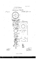
- FIG. 1 is a horizontal section of a puddling-furnace containing our improvement.
- Fig. 2 is a vertical longitudinal section of the same.
- Fig. 3 is a vertical transverse section of the same.
- Fig. 4 is a side View of the apparatus constituting the revolving bottom of our puddling-furnace.
- Fig..5 is avertical longitudinal section corresponding to Fig. 4.
- Fig. 6 is a top View of the revolving bottom, shown detached;
- Fig. 7, a vertical 4section of the bottom detached.
- Figs. 8 and 9 are detached views of the support for the revolving bottom.
- Figs. 10, 11, 12, 13, ⁇ 14, 15, 16, 17, 18 represent detached portions of the revolving furnace and the gearing, hereinafter explained.
- Fig. 19 is a detached View ofthe bed-plate for supporting the machinery.
- the puddling-furnace with a rotating or revolving bottom which can be constantly revolved during the puddling process, in conjunction with the use of a revolving tool adapted to the revolving bottom, for agitating the heated air and exposing it to the free decaibonizing action of the atmosphere.
- Fig. 2 shows a vertical longitudinal section of a puddling-furnace with our improvement.
- a A are the grate-bars.
- B is the door for charging the fuel.
- C is the opening of the tuyere.
- D D is the top or arch of the reverberatory furnace.
- E E is the fire-bridge wall.
- F F is the fine-bridge.
- Ve construct a bed of masonry, G G,to support a step, H H.
- This step H H is constructed with a ange extending all around it, for the purpose of retaining the oil, as shown in Fig. 2.
- I I is arevolvingbottom, which corresponds in diameter with the reverberatory furnace.
- I I' is a ring or circle of cast-iron, about one-foot deep, andof a diameter corre lsponding with the horizontal section of the furnace.
- Fig. 6 show the pieces composing the bottom of the revolving door I I.
- These pieces 1, 2, 3, and 4 are made of castiron, each being a quarter-circle, and are about one and one-half to two inches in thickness. These pieces are fitted together and laid upon a rim or projection around the lower edge of I I.
- the rim I I is cast so as to have a continuous circulatingtube through it for the passage of water to keep the revolving bottom from burning.
- This revolving bottom islined with cinder or other refractory material.
- This revolving bottom is supported in the following manner: A vertical shaft or spindle, K K', rests at its lower extremity upon a step,
- a eircular plate, l? P', Figs. 8 and 9, is cast.'- k Around the circumference of this plate is a flange of about eight or ten inches vertical projection.
- l? P is a circular groove or trough, Q Q, (see Figs. 10 and 11,) into which the flange on P P fits.
- the flange on l? 1? revolves in the trough or groove Q Q'.
- the trough Q Q is filled and kept full of water for maintaining an air-tight joint at the intersection of P P' and Q Q
- a bevel-wheel, R R' is placed on the lower part of the vertical shaft and another bevel-wheel gears into it. This second wheel is connected with the main driving power by any convenient gearing.
- a constant circulation of water is maintained through the vertical shaft and through the interior of the rim I I', and then through the circular trough or groove Q Q'.l
- the water enters at a, passes througha cup-and-ball joint at b into a tubular projection of the step H H', thence through the vertical shaft to the point d, whence it4 passes by the tube e to the point d, whence it passes by the tube e to the top of the tubular casing of the rim I I'.
- the water passes into the circular trough Q Q by the tube f, and thence escapes by the tube g.
- T T' T' and T' Ti T"
- T' T' and T' Ti T"
- This tool is the shape of a double screw with a half-twist. It is attached to a horizontal shaft, U U. The sections of the arms of this screw are triangular, as shown at t, Fig. 3, A.
- a constant circulation of water through the interior of the revolving tube T T is maini tained as follows: The water enters through the tube m, which connects by a water-box with the tubular passage n u', formed in the shaft U U'; thence the water passes through the 'tubular passage on the inside of T T' T and Areturns through the T" Ti", thence through Ti" T' T', thence through 7c k' kto the stuffing-box attached to the tube p, whence the water'iinally escapes.
- the shaft U U' is revalved constantly by any convenient power.
Landscapes
- Engineering & Computer Science (AREA)
- Mechanical Engineering (AREA)
- General Engineering & Computer Science (AREA)
- Vertical, Hearth, Or Arc Furnaces (AREA)
Description
N,FETERS, PHOTO-LITHOGRAPHER. WASHINGTON. D C.
ANirEn STATES PATENT EEIGE.
JOHN P. GROVE AND JOHN GROVE, OE MON'rOUE COUNTY, rm
IMPROVEMENT IN PUDDLING-FURNACES.
- Specification forming part of Letters Patent No. l9..1l3, dated April 6, 1858.
T0 all whom, it may concern:
Be it known that we, JOHN P. GROVE and JOHN GROVE, both of Montour county, in the State of Pennsylvania, have invented a new and useful Improvement in the Construction of Furnaces for Puddling Iron; and we do hereby declare the following to be a full and exact description of the same, reference being had to the annexed drawings, making a part of this specification, in which- Figure 1 is a horizontal section of a puddling-furnace containing our improvement. Fig. 2 is a vertical longitudinal section of the same. Fig. 3 is a vertical transverse section of the same. Fig. 4 is a side View of the apparatus constituting the revolving bottom of our puddling-furnace. Fig..5 is avertical longitudinal section corresponding to Fig. 4. Fig. 6 is a top View of the revolving bottom, shown detached; Fig. 7, a vertical 4section of the bottom detached. Figs. 8 and 9 are detached views of the support for the revolving bottom. Figs. 10, 11, 12, 13, `14, 15, 16, 17, 18 represent detached portions of the revolving furnace and the gearing, hereinafter explained. Fig. 19 is a detached View ofthe bed-plate for supporting the machinery.
Heretofore in the process of puddling iron it has been customary to heat the iron in a puddling or reverberatory furnace, and expose the heated iron to constant contact with the atmosphere by stirring up the heated mass while in the reverberatory furnace by means of appropriate tools worked by hand. This has always been found to be very severe labor, and in hot weather exceedingly exhausting on the men engaged in the work. Asmall quantity of iron only can be Worked at one time by the manner .in which puddling-furnaces have been heretofore constructed and used. My improvement has for its object the employment of artificial power for working the iron during the process of puddling; and it consists in constructing. the puddling-furnace with a rotating or revolving bottom, which can be constantly revolved during the puddling process, in conjunction with the use of a revolving tool adapted to the revolving bottom, for agitating the heated air and exposing it to the free decaibonizing action of the atmosphere. By this improvement a much larger mass of iron can be puddled at one time than heretofore.
The work can also be done more thoroughly, economically, and rapidly than by the old process, and much severe andexhausting labor is avoided. A great saving in fuel also is effected thereby.
To enable others skilled in the art to construct and use this improvement, we proceed to describe its construction and operation.
Fig. 2 shows a vertical longitudinal section of a puddling-furnace with our improvement. A A are the grate-bars. B is the door for charging the fuel. C is the opening of the tuyere. D D is the top or arch of the reverberatory furnace. E E is the fire-bridge wall. F F is the fine-bridge. These parts'are constructed in the ordinary manner.
Ve construct a bed of masonry, G G,to support a step, H H. This step H H is constructed with a ange extending all around it, for the purpose of retaining the oil, as shown in Fig. 2. Therejs no stationary bottom constructed, as is ordinarily placed in reverberatory furnaces, but I I is arevolvingbottom, which corresponds in diameter with the reverberatory furnace. several parts shown in Figs. 6 and 7.
I I', Fig. 7, is a ring or circle of cast-iron, about one-foot deep, andof a diameter corre lsponding with the horizontal section of the furnace.
1, 2, 3, 4, and 5, Fig. 6, show the pieces composing the bottom of the revolving door I I. These pieces 1, 2, 3, and 4 are made of castiron, each being a quarter-circle, and are about one and one-half to two inches in thickness. These pieces are fitted together and laid upon a rim or projection around the lower edge of I I. The rim I I is cast so as to have a continuous circulatingtube through it for the passage of water to keep the revolving bottom from burning. This revolving bottom islined with cinder or other refractory material. This revolving bottom is supported in the following manner: A vertical shaft or spindle, K K', rests at its lower extremity upon a step,
H H', and also passes through a box, L L,
which box rests upon a cross-plate, Z Z', attached to the masonry. Upon the top of the shaft K K a circularl plate of cast-iron, M M', rests. (Shown detached in Figs. 8 and 9.) This plate is keyed first to the shaft at its center. .This plate has two sets of circular projections or iianges cast upon its upper surface, and four sets of radial projections, so as to It is composed of the which extend down from the lower side of the.
tions of the bottom I I', having been fitted in-A.
to the plate M M' below, they are kept there by means of melted ciuder inserted therein.
On the under side of the' plate M M a eircular plate, l? P', Figs. 8 and 9, is cast.'- k Around the circumference of this plate is a flange of about eight or ten inches vertical projection. Immediately under this plate l? P is a circular groove or trough, Q Q, (see Figs. 10 and 11,) into which the flange on P P fits. The flange on l? 1? revolves in the trough or groove Q Q'. The trough Q Q is filled and kept full of water for maintaining an air-tight joint at the intersection of P P' and Q Q A bevel-wheel, R R', is placed on the lower part of the vertical shaft and another bevel-wheel gears into it. This second wheel is connected with the main driving power by any convenient gearing. By this construction of thebottom it can be made to revolve constantly while the puddling process is going on.
In order to keep the working parts from getting overheated or destroyed, a constant circulation of water is maintained through the vertical shaft and through the interior of the rim I I', and then through the circular trough or groove Q Q'.l The water enters at a, passes througha cup-and-ball joint at b into a tubular projection of the step H H', thence through the vertical shaft to the point d, whence it4 passes by the tube e to the point d, whence it passes by the tube e to the top of the tubular casing of the rim I I'. After pursuing a descending spiral course through this rim, the water passes into the circular trough Q Q by the tube f, and thence escapes by the tube g. By this means a constant circulation of water is maintained through the interior of the shaft and revolving bottom, and the parts are kept from burning and in working order.
In conjunction with the revolving bottom we also employ a revolving tool shaped as shown at T T' T' and T' Ti" T". It is com This tool is the shape of a double screw with a half-twist. It is attached to a horizontal shaft, U U. The sections of the arms of this screw are triangular, as shown at t, Fig. 3, A.
A constant circulation of water through the interior of the revolving tube T T is maini tained as follows: The water enters through the tube m, which connects by a water-box with the tubular passage n u', formed in the shaft U U'; thence the water passes through the 'tubular passage on the inside of T T' T and Areturns through the T" Ti", thence through Ti" T' T', thence through 7c k' kto the stuffing-box attached to the tube p, whence the water'iinally escapes. The shaft U U' is revalved constantly by any convenient power.
In order effectually and thoroughly to agitate and work the mass of heated iron, the direction of revolution of the bottom, and also of the tool, are reversed every ve minutesor thereabout. The eii'ect of the revolving bottom is to bring constantly to the action of the tool all parts of the mass of iron. The revolving tool thoroughly agitates the mass of iron as it is brought around by the revolving bottom.
Our improved puddling-furnaces, as above described, have enabled us to work a much larger quantity of iron at one time (with a great saving in fuel and with an improved quality of iron) than has been heretofore done. The work also is uniform 'in all seasons, and is independent of the skill of the workmen, and a great waste of material is avoided, in consequence of which the cost of puddling is greatly reduced.
Ve do not claim the invention of revolving bottoms for puddlingfurnaces; but
What we do claim is- 1. The employment of a revolving bottom for a puddling-furnace, arranged with watertubes for cooling it, and with the peculiar airtight joint described, the whole arranged and operating substantially as hereinbefore described. l
2. The employment, in a puddlingfurnace,
of a-revolving tool arranged and operating in l the manner and for the purpose substantially as above described.
J. I). GROVE. JOHN GROVE.
itnessesz i WILLIAM KITCHEN, W. G. PAIroN.
Publications (1)
| Publication Number | Publication Date |
|---|---|
| US19843A true US19843A (en) | 1858-04-06 |
Family
ID=2084291
Family Applications (1)
| Application Number | Title | Priority Date | Filing Date |
|---|---|---|---|
| US19843D Expired - Lifetime US19843A (en) | Improvement in puddli ng-fu rnaces |
Country Status (1)
| Country | Link |
|---|---|
| US (1) | US19843A (en) |
-
0
- US US19843D patent/US19843A/en not_active Expired - Lifetime
Similar Documents
| Publication | Publication Date | Title |
|---|---|---|
| US1903909A (en) | Rotary heat treating furnace | |
| US19843A (en) | Improvement in puddli ng-fu rnaces | |
| US1029234A (en) | Balling-furnace. | |
| US118674A (en) | Improvement in rotary puddling-furnaces | |
| US143301A (en) | Improvement in puddling-furnaces | |
| US29746A (en) | Improvement in deoxidizing ores | |
| US160140A (en) | Improvement in metallurgic furnaces | |
| US1155410A (en) | Metal-working furnace. | |
| US570129A (en) | Device for preventing obstruction of blast in blast-furnaces | |
| US659472A (en) | Gas-producer. | |
| US36954A (en) | Improved furnace for roasting ores and for other purposes | |
| US3531098A (en) | Apparatus for plugging and repairing tapholes in metallurgical furnaces | |
| US89310A (en) | Improved oscillating furnace for puddling and refining iron | |
| US658653A (en) | Puddling-furnace. | |
| US715080A (en) | Ore-roasting furnace. | |
| US155123A (en) | Improvement in revolving ore-roasters | |
| US129199A (en) | jackson | |
| US741549A (en) | Ore-roasting furnace. | |
| US130241A (en) | Improvement in apparatus for puddling and melting iron | |
| US361256A (en) | Benjamin bayliss | |
| US9303A (en) | Improved apparatus for puddling iron | |
| US639757A (en) | Rotary hearth and welding furnace. | |
| US1012872A (en) | Apparatus for balling scrap metal. | |
| US1859727A (en) | Copper treating furnace | |
| US73838A (en) | eivot |