US1979504A - Nozzle - Google Patents
Nozzle Download PDFInfo
- Publication number
- US1979504A US1979504A US569213A US56921331A US1979504A US 1979504 A US1979504 A US 1979504A US 569213 A US569213 A US 569213A US 56921331 A US56921331 A US 56921331A US 1979504 A US1979504 A US 1979504A
- Authority
- US
- United States
- Prior art keywords
- nozzle
- head
- slots
- face
- washing
- Prior art date
- Legal status (The legal status is an assumption and is not a legal conclusion. Google has not performed a legal analysis and makes no representation as to the accuracy of the status listed.)
- Expired - Lifetime
Links
- 238000005406 washing Methods 0.000 description 20
- 239000007921 spray Substances 0.000 description 18
- XLYOFNOQVPJJNP-UHFFFAOYSA-N water Substances O XLYOFNOQVPJJNP-UHFFFAOYSA-N 0.000 description 14
- 239000007788 liquid Substances 0.000 description 11
- 238000004851 dishwashing Methods 0.000 description 7
- 230000000694 effects Effects 0.000 description 4
- 241000543379 Cobaea scandens Species 0.000 description 2
- 238000010276 construction Methods 0.000 description 2
- 239000011521 glass Substances 0.000 description 2
- 238000005201 scrubbing Methods 0.000 description 2
- 238000004519 manufacturing process Methods 0.000 description 1
- 230000004048 modification Effects 0.000 description 1
- 238000012986 modification Methods 0.000 description 1
Images

Classifications
-
- A—HUMAN NECESSITIES
- A47—FURNITURE; DOMESTIC ARTICLES OR APPLIANCES; COFFEE MILLS; SPICE MILLS; SUCTION CLEANERS IN GENERAL
- A47L—DOMESTIC WASHING OR CLEANING; SUCTION CLEANERS IN GENERAL
- A47L15/00—Washing or rinsing machines for crockery or tableware
- A47L15/26—Washing or rinsing machines for crockery or tableware with movement of the crockery baskets by other means
- A47L15/30—Washing or rinsing machines for crockery or tableware with movement of the crockery baskets by other means by rotating only
- A47L15/32—Washing or rinsing machines for crockery or tableware with movement of the crockery baskets by other means by rotating only rotated by means of spraying water
Definitions
- NOZZLE Filed Oct. 16, 1931 2 Sheets-She'et 2 Patented Nov. 6, 1934 UNITED STATES NOZZLE Theodore Tafel, Jr., Ben Avon, Pa., assignor to Standard Sanitary Manufacturing Company, a corporation of- New Jersey Application October 16, 1931, Serial No. 569,213
- This invention relates to a machine for washing dishes and the like wherein the objects to be washed are supported in an openwork basket and are successively subjected to sprays of soapy water which cleanses the dishes and rotates the basket, and in particular, to an improved nozzle for directing the washing water against the dishes.
- An object of this invention is to provide means whereby washing water will be directed against the dishes to be washed at such an angle that both sides thereof will be thoroughly cleaned.
- Another object is to provide means for directing washing water against the dishes to be cleansed which will prevent the dishes from being slapped back and forth against each other.
- a further object is to provide means for preventing an excessive force of water from striking the lighter ware, such as the cups and saucers.
- a still further object is to provide means for effectively cleansing the lighter ware.
- a still further object is to provide a nozzle which is simple in construction and relatively cheap to manufacture.
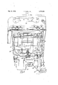
- Figure 1 is a front sectional view of a sink having a dishwashing chamber showing the location of the parts;
- Fig. 2 is a view in perspective of my improved nozzle
- Fig. 3 is a diagrammatic view. showing the direction of the washing spray
- Fig. 4 is a view in front elevation of my improved nozzle.
- Fig. 5 is a section taken on line V-V of Fig. 4.
- 10 designates a sink or other kitchen fixture having a dishwashing compartment 11 formed integral 45 therewith.
- a pin 12 Extending upwardly from the bottom of the washing chamber is a pin 12 on which an openwork wire rack 13 is rotatably mounted.
- the rack 13 comprises a basket 14 in which the heavier objects such as plates and the like, to be washed are placed, a perforated container 15 for receiving silverware and the like, and. a tray 16 on which the lighter ware, such as' the cups, saucers and glassware are supported.
- a drain pipe 17 Leading from the bottom of the washing chamber 11 is a drain pipe 17 having a valve 18 therein for opening and closing the outlet.
- the valve 18 is operated by a lever 19 secured to the upper portion of the fixture.
- a centrifugal pump 20 which is driven by a motor 21, is secured to the bottom of the washing chamber 11, and has the inlet side thereof connected to the drain pipe 1'7 above the valve 18.
- the pump 20 draws the washing water from the chamber 11 and forces 7 it through a nozzle 22 connected to the outlet side thereof which performs the double function of directing a plurality of wide consolidated impelling jets of the water against the dishes with sufficient force to cleanse them and to impart rotation to the rack 13 and also of simultaneously delivering a broken jet or spray of washing liquid onto dishes being washed.
- My improved nozzle 22 comprises a head portion 23 which is located near the bottom of the washing compartment adjacent the bottom of the basket 14.
- the head portion has a convex face 24 which faces toward the basket and is provided with a plurality of parallel arcuate slots 25 through which the washing water issues in fan-shaped sprays.
- the slots 25 are cut at an angle to the face 24 which is of suflicient thickness to have a directional effect on the water jets.
- the sprays designated as A. are substantially tangent to circles concentric to the axis on which the rack 13 is mounted.
- deflector plate 26 is secured across the upper portion of the face 24 of the head of the nozzle and covers the upper portion of the slots 25 so that the sprays will be deflected downwardly and broken up so as to enter tray 16 with only force enough to. washthe cups, etc., without lifting them from their position in the tray.
- a deflector plate 26 is secured across the upper portion of the face 24 of the head of the nozzle and covers the upper portion of the slots 25 so that the sprays will be deflected downwardly and broken up so as to enter tray 16 with only force enough to. washthe cups, etc., without lifting them from their position in the tray.
- a spoon-shaped deflector 28 is secured to the head 23 of the nozzle.
- the spoon 28 deflects the washing water at substantially right angles and projects a thin sheet or spray of water over the dishes and into the open end of the glasses in the tray 16 and over the silverware in the container 15.
- nozzle for a dishwashing machine wherein the nozzle serves the double purpose of scrubbing the dishes and rotating the dish-carrying rack. Itis also apparent that in my improved nozzle the sprays are fan shape, substantially parallel to each other and strike the dishes at such an angle that they are subjected to washing water on both sides thereof and are prevented from being slapped backward and forward against each other during their rotation.
- a nozzle for a dishwasher comprising an enlarged head having a plurality of parallel slots in one face and inclined relative to the longitudinal axis thereof, a deflecting member partially closing the slots in said face and a tube extending from said head and having a spoonshaped deflector at the top thereof.
- a nozzle for a dishwasher comprising a hollow head having a series of parallel slots in one face thereof, said slots being cut in said face at an angle to the surface thereof and disposed at an angle to the longitudinal axis thereof, a deflecting member partially closing the slots in said head and a tube extending from said head and terminating in a deflecting spoon.
- a nozzle for a dishwasher comprising a head having an upwardly and rearwardly curved face provided with a series of jet forming slots inclined relative to the longitudinal axis thereof, and a tube extending upwardly from said head and having a spoon-shaped deflector at the top thereof.
- a nozzle for a dishwashing machine comprising a head portion having an upwardly and rearwardly curved face provided with a series of obliquely cut slots extending upwardly of said face at an angle to the longitudinal axis thereof, said slotted face being of sufficient thickness as to have directional effect on the sprays issuing through said slots and a tube extending upwardly from said head and terminating in a spoonshaped deflector.
- a nozzle for a dishwashing machine comprising a head having an upwardly and rearwardly curved face provided with a series of parallel slots extending therethrough at an angle to the surface thereof, a deflecting member on said head partially covering the upper ends of said slots and a tube extending upwardly from said head and terminating in a spoon-shaped deflector.
- a nozzle for a dishwasher comprising a head having an upwardly and rearwardly curved face provided with a series of slots extending lengthwise thereof at an angle to the major axis thereof, a member on said head covering the upper ends of said slots, a tube extending verti- ,cally from said head portion and a deflector on said tube.
- a nozzle for a dishwasher comprising a head having a convex face provided with a series of parallel slots extending upwardly across said face at an angle to the vertical axis thereof and through said face at an angle to the surface thereof, and a deflecting member on said head covering the upper ends of said slots, said convex face being of a thickness suiflcient to have a directional effect on the sprays issuing through said slots.
- a nozzle for a dishwashing machine comprising a head having an upwardly and rearwardly curved face provided with a series of parallel slots extending lengthwise thereof at an angle to its vertical axis and through said face at an angle to the surface thereof, a deflecting member extending across said face and partially covering the upper ends of said slots, and a tube extending upwardly from said head and terminating in a spoon-shaped deflector, said convex face being of a thickness sufficient to have a directional effect on the sprays issuing from said slots.
- a double function nozzle for washing machines and the like comprising a liquid confining head having at least one elongated aperture formed in the wall thereof for directing a wide, substantially consolidated, impelling jet onto objects to be washed and for propelling the same, and having a second aperture formed in the wall thereof for simultaneously delivering a broken jet or spray of liquid onto the objects to be washed, whereby such objects to be washed are propelled by the jet issuing from said elongated aperture while being sprayed by liquid issuing from said second aperture.
- a double function nozzle for washing machines and the like comprising a liquid confining head having elongated slots formed in the wall thereof for directing a plurality of wide, consolidated, directional, impelling jets onto objects to be washed, and having a second aperture formed in the Wall thereof for delivering a broken jet or spray of liquid onto the objects to be washed whereby such objects receive an impelling impulse from the consolidated jets and are simultaneously sprayed by liquid delivered through the second aperture.
- a double function nozzle for washing machines and the like comprising a liquid confining head having a plurality of elongated slots formed in the wall thereof for directing a plurality of wide, substantially consolidated unidirectional impelling jets onto objects to be washed, and having a second aperture formed in the wall thereof and means associated with the second aperture for directing and breaking up the stream of liquid issuing therefrom whereby objects to be washed are simultaneously impelled by the impelling jets impinging thereon and showered with spray issuing from said sec-- ond aperture.
- a double function nozzle for washing machines and the like comprising a liquid confining head having substantially parallel elongated slots formed in the wall thereof for directing a plurality of wide, substantially consolidated, unidirectional, impelling jets onto objects to be washed, and having a second aperture formed in the wall thereof, a tube communicating with livering a plurality of unidirectional consolidated wide impelling jets onto objects contained within the basket, a tube communicating with the liquid chamber of the nozzle and extending upwardly to a point above the basket and a. deflector shielding the delivery'aperture of the tube whereby objects subjected to the impelling action of the wide jets are simultaneously subjected to a shower of spray issuing from said tube.
Description
T. TA-FEL, JR
NovQs, 1934.
NOZZLE Filed Oct. 16,1951
2 Sheets-Sheet l IIIIIIIIII- INV NTOR Nov. 6, 1934.
T. TAFEL,- JR
NOZZLE Filed Oct. 16, 1931 2 Sheets-She'et 2 Patented Nov. 6, 1934 UNITED STATES NOZZLE Theodore Tafel, Jr., Ben Avon, Pa., assignor to Standard Sanitary Manufacturing Company, a corporation of- New Jersey Application October 16, 1931, Serial No. 569,213
13 Claims.
This invention relates to a machine for washing dishes and the like wherein the objects to be washed are supported in an openwork basket and are successively subjected to sprays of soapy water which cleanses the dishes and rotates the basket, and in particular, to an improved nozzle for directing the washing water against the dishes.
An object of this invention is to provide means whereby washing water will be directed against the dishes to be washed at such an angle that both sides thereof will be thoroughly cleaned.
Another object is to provide means for directing washing water against the dishes to be cleansed which will prevent the dishes from being slapped back and forth against each other.
A further object is to provide means for preventing an excessive force of water from striking the lighter ware, such as the cups and saucers.
A still further object is to provide means for effectively cleansing the lighter ware.
A still further object is to provide a nozzle which is simple in construction and relatively cheap to manufacture.
These and other objects which will be apparent to those skilled in this particular art are accomplished by means of this invention, one embodiment of which is described in the following specification and illustrated in the accompanying drawings, wherein;
Figure 1 is a front sectional view of a sink having a dishwashing chamber showing the location of the parts;
Fig. 2 is a view in perspective of my improved nozzle;
Fig. 3 is a diagrammatic view. showing the direction of the washing spray;
Fig. 4 is a view in front elevation of my improved nozzle; and
Fig. 5 is a section taken on line V-V of Fig. 4.
Referring to the drawings in detail, 10 designates a sink or other kitchen fixture having a dishwashing compartment 11 formed integral 45 therewith. Extending upwardly from the bottom of the washing chamber is a pin 12 on which an openwork wire rack 13 is rotatably mounted. The rack 13 comprises a basket 14 in which the heavier objects such as plates and the like, to be washed are placed, a perforated container 15 for receiving silverware and the like, and. a tray 16 on which the lighter ware, such as' the cups, saucers and glassware are supported.
Leading from the bottom of the washing chamber 11 is a drain pipe 17 having a valve 18 therein for opening and closing the outlet. The valve 18 is operated by a lever 19 secured to the upper portion of the fixture. When the dishwasher is to be used, the table ware is placed 69 in the rack 13, the valve 18 is closed and washing water is poured into the chamber 11 until it covers the bottom of the basket 14.
In order to impart scrubbing action to the washing water, a centrifugal pump 20, which is driven by a motor 21, is secured to the bottom of the washing chamber 11, and has the inlet side thereof connected to the drain pipe 1'7 above the valve 18. The pump 20 draws the washing water from the chamber 11 and forces 7 it through a nozzle 22 connected to the outlet side thereof which performs the double function of directing a plurality of wide consolidated impelling jets of the water against the dishes with sufficient force to cleanse them and to impart rotation to the rack 13 and also of simultaneously delivering a broken jet or spray of washing liquid onto dishes being washed.
My improved nozzle 22 comprises a head portion 23 which is located near the bottom of the washing compartment adjacent the bottom of the basket 14. The head portion has a convex face 24 which faces toward the basket and is provided with a plurality of parallel arcuate slots 25 through which the washing water issues in fan-shaped sprays. The slots 25 are cut at an angle to the face 24 which is of suflicient thickness to have a directional effect on the water jets. As seen in Fig. 3, the sprays designated as A. are substantially tangent to circles concentric to the axis on which the rack 13 is mounted.
From the above construction it is readily apparent that, when the machine is in operation, vertically extending fan-shaped sprays will be directed against the plates and the like which are positioned in the basket 14 in such a way that they act as turbine vanes, and cause the rack 13 to rotate. In order to prevent the full force of the fan-shaped sprays from striking the cups and lighter ware placed in the tray 16, a
vertically extending tower 2'7, terminating in a spoon-shaped deflector 28 is secured to the head 23 of the nozzle. The spoon 28 deflects the washing water at substantially right angles and projects a thin sheet or spray of water over the dishes and into the open end of the glasses in the tray 16 and over the silverware in the container 15.
It is readily apparent that I have designed a nozzle for a dishwashing machine wherein the nozzle serves the double purpose of scrubbing the dishes and rotating the dish-carrying rack. Itis also apparent that in my improved nozzle the sprays are fan shape, substantially parallel to each other and strike the dishes at such an angle that they are subjected to washing water on both sides thereof and are prevented from being slapped backward and forward against each other during their rotation.
It is also apparent that with my improved type of nozzle very light and thin table ware may be readily washed without any danger of its being broken, since there is no possibility of its being turned over in the rack as it is not subjected to the excessive force of the washing sprays.
It is to be understood that certain modifications may be made without departing from this invention or the scope of the appended claims.
What I claim as new and desire to secure by Letters Patent is:
1. A nozzle for a dishwasher comprising an enlarged head having a plurality of parallel slots in one face and inclined relative to the longitudinal axis thereof, a deflecting member partially closing the slots in said face and a tube extending from said head and having a spoonshaped deflector at the top thereof.
2. A nozzle for a dishwasher comprising a hollow head having a series of parallel slots in one face thereof, said slots being cut in said face at an angle to the surface thereof and disposed at an angle to the longitudinal axis thereof, a deflecting member partially closing the slots in said head and a tube extending from said head and terminating in a deflecting spoon.
3. A nozzle for a dishwasher comprising a head having an upwardly and rearwardly curved face provided with a series of jet forming slots inclined relative to the longitudinal axis thereof, and a tube extending upwardly from said head and having a spoon-shaped deflector at the top thereof.
4. A nozzle for a dishwashing machine comprising a head portion having an upwardly and rearwardly curved face provided with a series of obliquely cut slots extending upwardly of said face at an angle to the longitudinal axis thereof, said slotted face being of sufficient thickness as to have directional effect on the sprays issuing through said slots and a tube extending upwardly from said head and terminating in a spoonshaped deflector.
5. A nozzle for a dishwashing machine comprising a head having an upwardly and rearwardly curved face provided with a series of parallel slots extending therethrough at an angle to the surface thereof, a deflecting member on said head partially covering the upper ends of said slots and a tube extending upwardly from said head and terminating in a spoon-shaped deflector.
6. A nozzle for a dishwasher comprising a head having an upwardly and rearwardly curved face provided with a series of slots extending lengthwise thereof at an angle to the major axis thereof, a member on said head covering the upper ends of said slots, a tube extending verti- ,cally from said head portion and a deflector on said tube.
7. A nozzle for a dishwasher comprising a head having a convex face provided with a series of parallel slots extending upwardly across said face at an angle to the vertical axis thereof and through said face at an angle to the surface thereof, and a deflecting member on said head covering the upper ends of said slots, said convex face being of a thickness suiflcient to have a directional effect on the sprays issuing through said slots.
8. A nozzle for a dishwashing machine comprising a head having an upwardly and rearwardly curved face provided with a series of parallel slots extending lengthwise thereof at an angle to its vertical axis and through said face at an angle to the surface thereof, a deflecting member extending across said face and partially covering the upper ends of said slots, and a tube extending upwardly from said head and terminating in a spoon-shaped deflector, said convex face being of a thickness sufficient to have a directional effect on the sprays issuing from said slots.
9. A double function nozzle for washing machines and the like comprising a liquid confining head having at least one elongated aperture formed in the wall thereof for directing a wide, substantially consolidated, impelling jet onto objects to be washed and for propelling the same, and having a second aperture formed in the wall thereof for simultaneously delivering a broken jet or spray of liquid onto the objects to be washed, whereby such objects to be washed are propelled by the jet issuing from said elongated aperture while being sprayed by liquid issuing from said second aperture.
10. A double function nozzle for washing machines and the like comprising a liquid confining head having elongated slots formed in the wall thereof for directing a plurality of wide, consolidated, directional, impelling jets onto objects to be washed, and having a second aperture formed in the Wall thereof for delivering a broken jet or spray of liquid onto the objects to be washed whereby such objects receive an impelling impulse from the consolidated jets and are simultaneously sprayed by liquid delivered through the second aperture.
11. A double function nozzle for washing machines and the like, comprising a liquid confining head having a plurality of elongated slots formed in the wall thereof for directing a plurality of wide, substantially consolidated unidirectional impelling jets onto objects to be washed, and having a second aperture formed in the wall thereof and means associated with the second aperture for directing and breaking up the stream of liquid issuing therefrom whereby objects to be washed are simultaneously impelled by the impelling jets impinging thereon and showered with spray issuing from said sec-- ond aperture.
12. A double function nozzle for washing machines and the like comprising a liquid confining head having substantially parallel elongated slots formed in the wall thereof for directing a plurality of wide, substantially consolidated, unidirectional, impelling jets onto objects to be washed, and having a second aperture formed in the wall thereof, a tube communicating with livering a plurality of unidirectional consolidated wide impelling jets onto objects contained within the basket, a tube communicating with the liquid chamber of the nozzle and extending upwardly to a point above the basket and a. deflector shielding the delivery'aperture of the tube whereby objects subjected to the impelling action of the wide jets are simultaneously subjected to a shower of spray issuing from said tube.
THEODORE TAFEL, JR.
Hit
Priority Applications (1)
| Application Number | Priority Date | Filing Date | Title |
|---|---|---|---|
| US569213A US1979504A (en) | 1931-10-16 | 1931-10-16 | Nozzle |
Applications Claiming Priority (1)
| Application Number | Priority Date | Filing Date | Title |
|---|---|---|---|
| US569213A US1979504A (en) | 1931-10-16 | 1931-10-16 | Nozzle |
Publications (1)
| Publication Number | Publication Date |
|---|---|
| US1979504A true US1979504A (en) | 1934-11-06 |
Family
ID=24274531
Family Applications (1)
| Application Number | Title | Priority Date | Filing Date |
|---|---|---|---|
| US569213A Expired - Lifetime US1979504A (en) | 1931-10-16 | 1931-10-16 | Nozzle |
Country Status (1)
| Country | Link |
|---|---|
| US (1) | US1979504A (en) |
Cited By (6)
| Publication number | Priority date | Publication date | Assignee | Title |
|---|---|---|---|---|
| US2619098A (en) * | 1945-04-17 | 1952-11-25 | Libbey Owens Ford Glass Co | Apparatus for washing glass sheets |
| US2645235A (en) * | 1947-09-29 | 1953-07-14 | Edwin F Wheeler | Automatic domestic dishwasher |
| US3064665A (en) * | 1960-12-01 | 1962-11-20 | Gen Electric | Dishwashing apparatus |
| US3500840A (en) * | 1967-11-30 | 1970-03-17 | Harvey R Maatz | Cleaning and sterilizing apparatus for barbering tools |
| US20050060813A1 (en) * | 2003-09-24 | 2005-03-24 | General Electric Company | Fluid-dispenser device conducive to reduced water consumption in a washing machine |
| US20150053243A1 (en) * | 2012-04-05 | 2015-02-26 | Due Gyu KIM | Dishwasher |
-
1931
- 1931-10-16 US US569213A patent/US1979504A/en not_active Expired - Lifetime
Cited By (7)
| Publication number | Priority date | Publication date | Assignee | Title |
|---|---|---|---|---|
| US2619098A (en) * | 1945-04-17 | 1952-11-25 | Libbey Owens Ford Glass Co | Apparatus for washing glass sheets |
| US2645235A (en) * | 1947-09-29 | 1953-07-14 | Edwin F Wheeler | Automatic domestic dishwasher |
| US3064665A (en) * | 1960-12-01 | 1962-11-20 | Gen Electric | Dishwashing apparatus |
| US3500840A (en) * | 1967-11-30 | 1970-03-17 | Harvey R Maatz | Cleaning and sterilizing apparatus for barbering tools |
| US20050060813A1 (en) * | 2003-09-24 | 2005-03-24 | General Electric Company | Fluid-dispenser device conducive to reduced water consumption in a washing machine |
| US20150053243A1 (en) * | 2012-04-05 | 2015-02-26 | Due Gyu KIM | Dishwasher |
| US9585537B2 (en) * | 2012-04-05 | 2017-03-07 | Dae Gyu Kim | Dishwasher |
Similar Documents
| Publication | Publication Date | Title |
|---|---|---|
| KR940011551B1 (en) | Tableware washing machine | |
| RU2660030C2 (en) | Dishwasher containing at least one dishwasher spraying device | |
| US2501887A (en) | Dishwasher | |
| US3051184A (en) | Apparatus for washing articles | |
| US1979504A (en) | Nozzle | |
| US2218869A (en) | Dishwashing machine | |
| EP4245205A2 (en) | Fan-shaped spray detergent nozzle | |
| US2345185A (en) | Washing apparatus | |
| US2664903A (en) | Dishwasher | |
| CN109965804B (en) | Cleaning machine | |
| US2704084A (en) | Dishwashing machine | |
| CN109394107A (en) | A kind of cleaning machine | |
| US1813807A (en) | Washing machine | |
| US1642933A (en) | Device for washing dishes and the like | |
| KR100232276B1 (en) | Dishwasher | |
| US1686456A (en) | Dishwashing machine | |
| US1473301A (en) | Bishwashzjjx ssachihb | |
| US2588856A (en) | Rotary spray arm for washing machines | |
| US1655354A (en) | Dishwashing machine | |
| CN111328269B (en) | Spray arm assembly of dish washer | |
| JP2539289B2 (en) | dishwasher | |
| US1977977A (en) | Dishwashing machine | |
| JP5848004B2 (en) | Cooking pot cleaning equipment | |
| US1435212A (en) | Dishwashing apparatus | |
| US1946536A (en) | Dishwashing machine |