US1979339A - Candle socket - Google Patents
Candle socket Download PDFInfo
- Publication number
- US1979339A US1979339A US549346A US54934631A US1979339A US 1979339 A US1979339 A US 1979339A US 549346 A US549346 A US 549346A US 54934631 A US54934631 A US 54934631A US 1979339 A US1979339 A US 1979339A
- Authority
- US
- United States
- Prior art keywords
- socket
- shell
- legs
- switch
- frame
- Prior art date
- Legal status (The legal status is an assumption and is not a legal conclusion. Google has not performed a legal analysis and makes no representation as to the accuracy of the status listed.)
- Expired - Lifetime
Links
Images

Classifications
-
- F—MECHANICAL ENGINEERING; LIGHTING; HEATING; WEAPONS; BLASTING
- F21—LIGHTING
- F21S—NON-PORTABLE LIGHTING DEVICES; SYSTEMS THEREOF; VEHICLE LIGHTING DEVICES SPECIALLY ADAPTED FOR VEHICLE EXTERIORS
- F21S6/00—Lighting devices intended to be free-standing
- F21S6/001—Lighting devices intended to be free-standing being candle-shaped
Definitions
- Fig. 13 is aperspective' view of a conductor constituting ⁇ part of the circuit of the socket.
- a pull-chain socket comprising, in combination, ⁇ a lamp-receiving shell, a pair of spaced legs supporting said shell, a rotary switch positioned between said legspswitch-actuating means positioned exteriorly ofv said legs and projecting ⁇ through one of said legs into engagement with said switch, a bracket secured to said last mentioned leg forming a shield for saidswitch-actuating means, and a oatingshaft supporting said switch and said actuating means journaled atene ⁇ end in said bracket and at the other en in the remote leg.
Description
Ewan/.N JCLLYL JL. L?
2 Sheets-Sheet l K. K. NIELSEN CANDLE SOCKET Filed July 8, 1931 Nov. 6,` 1934.
NOV. '6, 1934. K K, NlELSEN 1,979,339 I CANDLE SOCKET Fld July 8, 1931 h 2 Sheets-Sheet 2 24 J3. Mmm/m54 Patented Nov. 6, 1934 PATENT OFFICE CANDLE SOCKET .Karl K. Nielsen, Chicago, Ill., assignor to Alcor Manufacturing Company, Chicago, Ill., a corporation `of rIllinois Application July 8, 1931, Serial No. 549,346 15 claims. (o1. 17e- 354)l This invention relates to electric lamp sockets and more particularly to the type known as candle sockets.
Itis an object of the invention to provide `a candle socket and switch mechanism therefor of improved and simpliedconstruction and compact arrangement.
Another object of the invention is to provide a socket with a metallic frame having atswitch and switch-actuating mechanism, and means forming with` the switch an electric circuit independently of and totally insulated from the frame and the `switch-actuating mechanism.
` A further object of the invention is to provide a candle socket having an improved pull-chain switch wherein the parts are arranged so that the chain is at all times effectually insulated.
Still another object of the invention is to provide a switch socket wherein the parts are secured together simply and eiectually and in a manner such as to facilitate assembly.
Other objects and advantages will become apparent from the following' description and from the drawings in which:
Figure 1 is a vertical view in `elevation of a switch socket embodying the features of this invention. A candle-simulating tube concealing the socket is shown in section. l
Fig. 2 is an elevational view of the socket looking from the right in Fig. 1 withthev bracket partially broken away.
. Fig. 3 is an elevational View of the socket looking from the rear of Fig. 1.
Fig. 4 is a vertical sectional View plane of line 4-4 of Fig. 2.
Fig. 5 is a fragmental view showing the chainsupporting segment rotated and engaging its stop. j j
Fig. 6 is a fragmental `vertical sectional view taken approximately in the plane Ofline 6 Of Fig. l.. j
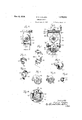
Fig. 7 is a perspective view of the bracket.
Fig. 8 is a perspective view of the oscillatory actuating member.
Fig. 9 is a side elevational view of the toothed switch disk.
Fig.-10 is a perspective View `of the conducting sheath forthe toothed disk.
taken in the Fig. 11 is a side elevational View of an insulating washer.
Fig. 12` is a perspective view of a disk forming a part ofthe ratchet connectionbetween the toothed disk `and the oscillatoryl member.
Fig. 13 is aperspective' view of a conductor constituting `part of the circuit of the socket.
l Fig. 14 is a `view` taken approximately in the plane of line 14-14 of Fig. 1.
For purposes ofA illustration, the invention is here shown as` embodied in a candle socket of the pull-chain type generally disclosed in my pending application Serial No. 342,332, filed February 25, 1929 of which this application is a continuation in part.
Thebody of the socket is composed of a twopart extensible metallic frame, the upper portion of which is formed by anlinverted U-shaped member 20 having a pair of substantially parallel legs 21 and 22. These legs are channel shaped in transverse cross-section (see Fig. 14) and are connected at their upper end by an in- .tegral web `23 centrally apertured. At their lower. ends,` the legs 21, 22 are made rigid by a web 24 havinglugs 25 projecting through the legs and clinched. on the outside` thereof.` The web 24. iscircular n outline and is cut away at diametrically opposite portions to receive the legs. It is also cut .away at the intermediate portions (see Fig. 14) to provide forthe lead wires of the socket. The remaining projecting portions provide shoulders for supporting a candle simulating tube 26 encasing the socket.
Adjustably secured to `the ends of the legs is the lower part of the frame which is-formed by an upright `U-shaped member 27 having a tubular-intermediate portion 28 threaded internally to be screwed onto a fixture. The legs of the upright member 27 are slidable in the channels ofthe legs 21 and 22 and are held against withdrawal ,by means of bolts 29 projecting through longitudinal slots 30 formed in the legs of the upright member. Itis thus apparent that the frame of the socket is a simple open structure easily made and assembled and wholly free of easily breakable material.
Supported at the upper end of the frame is a vlamp-recrzeiving shell 31, the base of which is -formed by an Vinwardly projecting annular flange 34a as `is the web. The shell and the frame are thus made rigid by clamping the flange 32 and the web 23 between the washers which in turn insulate the rivet, the shell and the frame from each other. The rivet also acts as the center contact of the socket, the other contact being formed by the shell 31.
With the frame constructed wholly of metal, grounding of the socket through the fixture is very possible, and precaution must be taken to avoid such an occurrence. To that end the electric circuit of the socket is here composed of means wholly independent of the frame which` supports them but which is well insulated therefrom.
The shell 31, which as'stated forms one contact of the socket and thus constitutes a part of the circuit, has riveted directly thereto a conducting strip 36 (Fig. 6) disposed at right angles to the frame legs 21, 22 (Fig. 3) said strip extending downwardly so as to terminate just short of the web 24. At its lower end, the strip 36 carries a. wire-securing screw 37 constituting one terminal for the attachment of the lead wires which are brought into the socket through the tubular portion 28.
The other wire terminal of the socket is disposed directly opposite the terminal 37 and is supported by the web 24. This terminal comprises a right-angled strip 33 having an upright portion 39 carrying a wire securing screw 40, and a. horizontal portion 41 extending parallel with the web 24 but spaced therefrom by a sheet 42 of insulation.
Forming part of the switch for the circuit is a spring contact 43 (Fig. 6) projecting upwardly into the space between the legs 21, 22. This contact has a horizontal portion 44 immediately overlying the terminal portion 41. To secure the spring contact 43 and the strip 41in position, a sheet 45 of insulation is placed on top of the horizontal portion and the entire group fixed to the web 24 by a single rivet 46. In order that the rivet 46 may not come in contact with the' horik zontal portion of either the strip 38 or the spring contact 43, both are formed with an opening substantially larger than the diameter of the rivet 46 and a washer 47 of insulating material'whose thickness isequal to the combined thickness of both horizontal portions is inserted between the rivet 46 and the horizontal portions. Here again the circuit is effectively insulated from the frame and a simple and uniquey mounting provided for the terminal.
Completing the stationary portion of the circuit between the center contact 35 and the terminal 39, 41 is a conductor 48 (see Figs. 1, 6 and 13) particularly shaped for use in a socket of the type here described. The conductor 48 is formed with a horizontal portion 49 adapted to be positioned within the shell 31 and secured bythe rivet 35 which projects through one end of the portion 49 and is in electrical contact therewith. The portion 49 of the conductor within the shell 31 lies on top of the washer 34 and is thus insulated from the flange 32, while the shell 31 proper is cut away at 50 to permit the conductor to project outwardly of the shell. At the circumference of the shell 31, the conductor is bent downwardly and laterally to extend into the space deiined by the frame members 21, 22. The free end of the conductor 48 terminates in an annular ring 51 lying in a plane parallel with the leg 21 and spaced therefrom by a sheet 52 of insulation. The sheet 52 of insulation is of a width approximately equal to the diameter of the socket, and of a length'such as to extend between the washers 34a and 45 (Fig. 4).
Interposed between the annular ring 51 and the spring contact 43 is a rotary switch member mounted on a shaft 53 extending transversely of the legs 21, 22 of the frame. In the present instance, the switch member comprises a fourtoothed disk 54l (Fig. 9) of insulating material carrying a sheath 55 (Fig. 10) of conducting material partially encasing the disk. The sheath 55 is composed of an annular ring 56, conforming in size to the ring 51 of the conductor, and arcuate flanges 57 covering the peripheral surface of alternate teeth of the disk. Both rings have an inner circumference large enough to be eiectively insulated from the shaft.
The disk 54 is disposed with the ring 56 of the sheath and the ring 51 of the conductor concentric and in contact, while the periphery of the disk 54 is in contact with the spring contact 43.
With this construction, a switch having but a single point of make and break is provided, and all parts forming the switch may be conveniently grouped near one leg 21 of the frame, from which it is insulated by the sheet 52. At the same time the switch is spaced from the leg 22 a sufficient distance to obviate the necessity of special insulation.
It will be seen that when the spring contact 43 engages a tooth covered by the sheath 55 a circuit is completed from the terminal strip 39 through the contact 43, the sheath 55 and the conductor 48, then through the lamp turned into the socket, the shell 31 and the strip 36. A quarter of a turn of the disk 54 positions an uncovered tooth in engagement with the spring contact 43 and thus breaks the circuit.
To avoid accidental closing of the circuit by engagement of the ring 56 and the spring contact 43 when the latter is in engagement with an uncovered tooth, a specially shaped washer 58 (Fig. 1l) is positioned between the disk 54 and the sheath 55. As may be seen from said figure, the washer is circular in outline and of a diameter larger than the maximum diameter of the disk 54. Two quarters of the washer 58 are cut to conform to thev shape of the disk teeth, thus permitting the sheath 55 to be slipped over the washer and onto the disk, the washer being held thereby against rotation relative to the disk. The other two quarters, being normal, project radially well beyond the disk 54 and thus prevent contact between the ring and the spring contact.
The disk 54 is rotated in the present instance through a ratchet connection, by an oscillatory member 59 carrying a pull-chain 60. For this purpose, the disk is formed with a pair of diametrically opposite holes 61 which receive prongs 62 projecting from a metal disk 63 (Fig. 12) formed with a pair of diametrical slots 64 at right angles to each other. The metal disk 63 when assembled with the toothed disk 54 thus forms one part of a ratchet connection rotating the disk.
The other part of the ratchet connection is formed on the oscillatory member 59 which comprises a segment 65 which supports the pullchain 60 and a tubular portion 66 rotatable on the shaft 53 and terminating in ratchet teeth 67 for engaging the slots in the disk 63.
To insure that the pull-chain will not contact with any part of the electric circuit, the tubular `portion 66 of the oscillatory member is made longer than the distance between the disk 54 ber 59.
imanes 3` and the leg "2'2 tnerebyensuimg the ehainasp porting segment '65 tobe positioned exteriorly of the space between the legs. Theleg 22 is `apertured topermit-the tubular portion `66 to project therethrough andmay,if desired, form aibearing for the oscillatory member. `The pull-chain 60 is also guided by passing through anaper` ture 68 in the projecting portion of the `web 124. With the electric circuitconcentrated near the leg 21, and the chain mounted outside of the leg 22 all 4possibility of contactbetween thchain and the electric circuit is eliminated.
For convenience in assembling the pull-chain socket, theshaft 53, `supporting the rotaryswitch member and theoscillatory member 59, is prefer# ably a floating shaft having shouldered ends, one journaled in the leg 21 while the `other projects through the leg 22 and isjournaled `in a bracket 69 riveted to the outside of vthe leg.` By the use of a floating shaft 4all parts may iii-st "be positioned and the shaftl then `inserted and *held against lateral movement bythe bracket69. It also provides for a simple construction resulting in a two bearingsupport for the shaft.
In addition to providing a bearing for the shaft 53, the bracket 69 serves as a shield for `the segment protecting itagainst any binding vaction on the part of the candle-simulating tube 26 slid over the socket, and also as an abutment for arresting'the movements ofthe oscillating mem- Eorthispurpose the `bracket 69 has a lug 'l0 projecting4 intothe path of the oscillating segment 65 intermediate its ends.` In the normal positionof the oscillatory member`59 (see Fig. 2) the end to which the pullfchain is attached abuts the lugs 70 thereby limiting rotation in a counter-clockwise direction as viewed in that figure. The member 59 is `urged to normal `position by a torsion spring'71attached at one end to the free end ofthe segment 65 (see Figs; 2 and 5) and anchoredat the lother end on the lug 70 of the bracket. This spring also acts in compression between `the bracket 69 and the oscillating member `59 to `'yieldably retain the teeth'? in engagement with the disk 63.
To advance the switch member to make or breakthe circuit, the member 59 is oscillated by means of the pull-*chain tothe position shown 5 in whichiposition` the 'free end of the segment abuts` the lug '70. The degree of rotation isdetermined by thesize of the segment 65 which is here made slightly longerthan asemtcircle. The permissible rtation'isfthus less-'than 180` and permits the switch member to be adi vanced by one tooth only. This insures that each operation of the pull-chain will cause only a making or a breaking of the circuit and not both in the same operation.
I claim as my invention:
1. A pull-chain socket comprising, in combination, a lamp-receiving shell, a pair of spaced legs supporting said shell, a switch member rotatably mounted between said legs, and an oscillatory actuating member comprising an elongated tubular portion having a ratchet connection with said switch member and projecting through one of said legs, and a chain supporting segment rigid with the projecting end of said tubular portion.
2. A pull-chain socket comprising, in combination, a lamp-receiving shell, a pair of spaced legs supporting said shell, switch mechanism mounted between said legs, an oscillatory actuating means located outside of said legs and having a portion projecting through one of `said legs into engagement with said mechanism, and a bracket secured to said last mentioned leg forming a shield for said actuating means. e y y 3: A pull-chain socketcomprising, in combination, `a lamp-receiving shell, a pair of spaced legs supporting said shell, a rotary switch positioned between said legspswitch-actuating means positioned exteriorly ofv said legs and projecting `through one of said legs into engagement with said switch, a bracket secured to said last mentioned leg forming a shield for saidswitch-actuating means, and a oatingshaft supporting said switch and said actuating means journaled atene `end in said bracket and at the other en in the remote leg. f 4. A pul1`-chain socket comprising, in combination, a lamp-receiving shell, a pair of spacedlegs supporting saidshell, a bracket secured to the outside of one of said legs, a rotary switch mounted between saidiegs, an oscillating switch-aotuating member having a segmental chain supporting `portion positioned between said bracket and said leg and a tubular portion journaled in said leg'having a ratchet engagement with said switchpa lug on said bracket limiting the rotal tional movement of said actuating member, and a torsion spring acting in compression between said bracket and said member to retain it in engagement with said switch, said spring having one end attached to said segmental portion and the other end anchored to said lug.
5: A switching electric lamp socket comprising,
-in combination, a lamp-receiving shell, a metallic frame supporting saidshell, said frame and said shell being insulated from each other, a center contact for said shell `insulated therefroinand 'having an arm extending within said `frame, a
conducting strip in contact with said shell but insulated from said frame and having at its terminus `a wire receiving terminal, a second wire terminal having a spring contact projecting into the spacewithin said frame, and a movable switch member insulated from said frame and interposed `between 4said arm and said' spring contact.
' 6.` electric lamp socket having a shell, an elongated metallic frame having the shell secured to one end in insulated relation thereto, said frame having a vpair of spaced parallel legs, a shaft mounted in said legs parallel to the base of the shell, wire 'terminals onesecured to the'shell and the other mounted on the frame but insulated therefrom, a conductorforming the" `center contact of the shell,` a second conductor secured to the terminal on the frame, and a rotary switch member on said shaft insulated'therefrom and adapted to coact with said conductors.
7. An electric lamp socket comprising, incombination, a lamp-receiving shell, a metallic frame supporting said shell but insulated therefrom, conducting means including a switch insulated from the frame and mounted within the space defined by the frame and forming with said shell the electric circuit of said socket, and means for actuating said switch mounted in spaced relation to the conducting means.
8. A pull-chain socket comprising, in combination, a lamp-receiving shell, a pair of spaced legs supporting said shell, a web rigidly connecting the free ends of said legs, said web projecting outwardly beyond said legs, a wire terminal supported by said web, a rotary switch member coacting with said terminal, an oscillatory switch actuating member located exteriorly of the space between said legs and projecting through one of said legs into engagement with said rotary member, and a pull-chain attached to said actuating member `and guided by a portion off-said web projecting beyond said legs.
9. A lamp socket comprising, in combination, a lamp-receiving shell, a pair of spaced metallic legs supporting said shell but insulated therefrom, a center contact for said shellhaving an arm projecting between said legs parallel with the plane thereof, a rotary switch member mounted on an axis extending transversely of said legs, said switch member being in continuous engagement with said arm, a wire terminal having a spring contact engaging the periphery of said switch member, and a sheet of insulation interposed between said arm and one of said legs.
10. A lamp socketof the shell contact type comprising, in combination, a lamp-receiving shell, a pair of spaced legs supporting said shell, a shaft supported between said legs, a toothed insulating disk on said shaft, a conducting-sheath for said disk comprising an annular ring and anged segments at right angles thereto covering the peripheral faces of alternate teeth, a spring contact in engagement with the periphery of said disk, and a center contact for said socket having an annular ring encircling the shaftin continuous engagement with said sheath, both of said rings being out of contact with said shaft.
11. l An electric lamp socket comprising, in combination, a lamp-receiving shell, a frame supporting said shell, a toothed insulating disk rotatably mounted in said frame, a conducting sheath for said disk having portions covering the peripheral surfaces of alternate teeth, a spring contactengaging the periphery of said disk to form therewith a switch for the circuit of the socket, and an insulating washer interposed between said sheath and said disk having alternate portions corresponding in contour to the shape of the teeth, the other portions being positioned opposite the uncovered teeth and projecting radially beyond the teeth to prevent contact between said sheath and said spring contact.
n l2. An electric lamp socket comprising, in combination, a lamp-receiving shell, a frame supporting said shell, a toothed insulating disk rotatably mounted in said frame, a conducting sheath for said disk having an annularfring portion and segmental portions` covering the peripheral surfaces of alternate teeth, a spring contact engaging the periphery of said disk to form therewith a. switch for the circuit of the socket, and an insulating washer interposed between said annular ring and said disk having portions placed opposite the uncovered teeth, which portions project radially. beyond the periphery of said disk to prevent contact between said ring and said spring contact.
v 13. An electric lamp socket comprising, in combination, a lamp-receiving shell, a metallic frame supporting said shell in insulated relation, an electric circuit for said socket wholly independent of said frame, said circuit including said shell, conducting strips and a movable conducting member forming with said strips a switch for the circuit, each of said strips and member being fully insulated from said frame, switch actuating means mounted on said frame and operatively connected with said movable member, and a member 'of insulating material interposed between said switch actuating means and said movable conducting member to complete the insulatingof the electric circuit from said frame and. said switch actuating means.
14. An electric lamp socket comprising, in combination, a lamp-receiving shell, a metallic frame supporting said shell in insulated relation, said frame beingk adapted to bemounted directly on a metallic supporting conduit or the like, an electric circuit for said socket wholly independent of said frame, said circuit including said shell, conducting strips and a movable conducting member forming with said strips a switch for the circuit, switch actuating means mounted on said frame including a metallic pull chain extending along said frame and having an operative connection with said member, -and a member of insulating material interposed between said switch actuating means and said movable conducting member, said conducting strips and movable member being completely insulated from said metallic frame to form with said shell an electric circuit wholly independent of said frame.
15. A vpull chain socket comprising, in combination, a lamp-receiving shell, a pair of laterally spaced legs supporting said shell, a rotary switch positioned between said legs, oscillatory actuating means for said switch positioned outside of said legs, a shaft supporting said actuating means and rotatably supporting said switch and having reduced end portions, the leg adjacent said oscillatory actuating means having an aperture permitting the endwise insertion of said shaft therethrough, and a bracket secured to the outside of said lasty mentioned leg receiving the A reduced portion of one end of said shaft, the reduced portion ofthe other end of said shaft terminating in the remote leg.
f KARL K. NIELSEN.
Priority Applications (1)
| Application Number | Priority Date | Filing Date | Title |
|---|---|---|---|
| US549346A US1979339A (en) | 1931-07-08 | 1931-07-08 | Candle socket |
Applications Claiming Priority (1)
| Application Number | Priority Date | Filing Date | Title |
|---|---|---|---|
| US549346A US1979339A (en) | 1931-07-08 | 1931-07-08 | Candle socket |
Publications (1)
| Publication Number | Publication Date |
|---|---|
| US1979339A true US1979339A (en) | 1934-11-06 |
Family
ID=24192617
Family Applications (1)
| Application Number | Title | Priority Date | Filing Date |
|---|---|---|---|
| US549346A Expired - Lifetime US1979339A (en) | 1931-07-08 | 1931-07-08 | Candle socket |
Country Status (1)
| Country | Link |
|---|---|
| US (1) | US1979339A (en) |
-
1931
- 1931-07-08 US US549346A patent/US1979339A/en not_active Expired - Lifetime
Similar Documents
| Publication | Publication Date | Title |
|---|---|---|
| US1979339A (en) | Candle socket | |
| US2692375A (en) | Electric lamp having a base provided with insulation piercing means to connect it to a twin conductor | |
| US2799743A (en) | Multiple lamp sockets, switch, and housing | |
| US1926206A (en) | Volume control device | |
| US2217395A (en) | Lamp socket | |
| US2123103A (en) | Electrical connecter | |
| US2341750A (en) | Combined volume control and switch | |
| US1776664A (en) | Rheostat | |
| US1760138A (en) | Combination electric plug and switch | |
| US3882450A (en) | Lamp | |
| US1779601A (en) | Rheostat | |
| US3702931A (en) | Device made from insulating material for electrical insulation of a switch in a work-lamp shield | |
| US1506063A (en) | Electric candle-socket structure | |
| US1636587A (en) | Electric-cord reel | |
| US2212382A (en) | Socket for electric lamps | |
| US1858422A (en) | Rheostat-lamp socket | |
| US1053552A (en) | Electric switch. | |
| US1335023A (en) | Sylvania | |
| US1666248A (en) | Three-way lamp socket | |
| US277642A (en) | Edwakd weston | |
| US1750740A (en) | Current regulator for electric lamps | |
| US1660317A (en) | Stand-lamp construction | |
| US1750739A (en) | Lamp-socket rheostat | |
| US1301152A (en) | Lamp-socket. | |
| US1647250A (en) | Electric switch |