US1978232A - Pump - Google Patents
Pump Download PDFInfo
- Publication number
- US1978232A US1978232A US489747A US48974730A US1978232A US 1978232 A US1978232 A US 1978232A US 489747 A US489747 A US 489747A US 48974730 A US48974730 A US 48974730A US 1978232 A US1978232 A US 1978232A
- Authority
- US
- United States
- Prior art keywords
- diaphragm
- pump
- housing
- resistance
- wedge
- Prior art date
- Legal status (The legal status is an assumption and is not a legal conclusion. Google has not performed a legal analysis and makes no representation as to the accuracy of the status listed.)
- Expired - Lifetime
Links
Images
Classifications
-
- F—MECHANICAL ENGINEERING; LIGHTING; HEATING; WEAPONS; BLASTING
- F04—POSITIVE - DISPLACEMENT MACHINES FOR LIQUIDS; PUMPS FOR LIQUIDS OR ELASTIC FLUIDS
- F04B—POSITIVE-DISPLACEMENT MACHINES FOR LIQUIDS; PUMPS
- F04B43/00—Machines, pumps, or pumping installations having flexible working members
- F04B43/0009—Special features
- F04B43/0054—Special features particularities of the flexible members
-
- F—MECHANICAL ENGINEERING; LIGHTING; HEATING; WEAPONS; BLASTING
- F04—POSITIVE - DISPLACEMENT MACHINES FOR LIQUIDS; PUMPS FOR LIQUIDS OR ELASTIC FLUIDS
- F04B—POSITIVE-DISPLACEMENT MACHINES FOR LIQUIDS; PUMPS
- F04B43/00—Machines, pumps, or pumping installations having flexible working members
- F04B43/02—Machines, pumps, or pumping installations having flexible working members having plate-like flexible members, e.g. diaphragms
-
- F—MECHANICAL ENGINEERING; LIGHTING; HEATING; WEAPONS; BLASTING
- F04—POSITIVE - DISPLACEMENT MACHINES FOR LIQUIDS; PUMPS FOR LIQUIDS OR ELASTIC FLUIDS
- F04B—POSITIVE-DISPLACEMENT MACHINES FOR LIQUIDS; PUMPS
- F04B9/00—Piston machines or pumps characterised by the driving or driven means to or from their working members
- F04B9/02—Piston machines or pumps characterised by the driving or driven means to or from their working members the means being mechanical
- F04B9/04—Piston machines or pumps characterised by the driving or driven means to or from their working members the means being mechanical the means being cams, eccentrics or pin-and-slot mechanisms
- F04B9/042—Piston machines or pumps characterised by the driving or driven means to or from their working members the means being mechanical the means being cams, eccentrics or pin-and-slot mechanisms the means being cams
Definitions
- This invention relates to a pump and particularly to a pump adapted to delver a small quantity of fluid under great pressure and with great speed.
- Figure 2 is an elevation of the pump, showing in part the Operating means.
- A is a pump body or housing that is preferably provided in one face with a raised land A1 which co-operates to form a depression or pump chamber portion A2.
- A3 is a cavity formed in the lpump body A and provided adjacent one end With an inwardly extending shoulder or reduced portionA.
- An inlet valve housing may be seated in the cavity A3.
- A5 is another cavity formed in the body portion A and provided adjacent one end with a shoulder or reduced portion A5.
- An outlet valve housing may be positioned withvin the cavity A5 and may rest against the shoulder or reduced portion A5. Extending .through the body portion A and communicating with the pump chamber and with the outside of the pump is an air vent A7.
- A8 is a controlling valve there-e for, preferably provided with a handle .or manipulating part A by means of which it may be moved into and out of position to control'the air vent.
- the air vent while it may be placed in any 'suitable location, is preferably in an extension' A1o formed as a part of the valve body.
- a retaining portion B of generally annular shape. It may be fastened to the valve body by screws B1 or by any other suitable means.
- This diaphragm may be 65 made of any suitable material and it serves 1930, Serial No. 489,747
- a sealing or closing member to complete the pump chamber.
- a plurality of laminations C1 Positioned within the pump chamber or cavity A2 and bearing upon the portion A and upon the diaphragm C is a plurality of laminations C1 which, together, form an internal laminated spring. They are so shaped land proportioned that they tend to force the diaphragm C outward and do so whenever they are free to move.
- a support D supported from and preferably made integral with the retaining member B is a support D.
- This support is in effect a loop provided with oppositely placed parts which are fastened to the annulus B and 'provided with a portion joining these two, so that it thus provides a loop over the valve disc or diaphragm.
- E is a compression plate positioned against the diaphragm, C.A It is provided with one generally fiat face which lies against the diaphragm and it is somewhat rounded or tapered away adjacent its edges as at E1. On its opposite face it carries a boss E2 and a helical race E3. Tapered rollers E4 are mounted to run in the helical race E3.
- F is a rocking member provided with a depression F1 which is seated upon the boss E2.
- the rocking member is provided on one face with a helical race F2 and on its opposite side with a fiat race F'3 within which tapered rollers F4 are positioned and adapted to move.
- At one edge and extending outwardly from the rocking member F is a pair of ears F5, F5.
- a drive rod or shaft F5 Positioned between the ears is a drive rod or shaft F5 which may be moved by any suitable mechanism back and forth, as indicated by the arrow in Figure 2.
- F1 is a boss formed on the member F, opposite the depression F1.
- G is a bearing supporting member resting upon the boss F7 of the member F and provided with a flat bearing race G1.- The member G rests against the support D.
- H is an inlet valve housing adapted to be seated in the cavity A3 in the pump body A. It is provided with a bore H1 which has at one end a valve seat portion H2- H3 is a valve positioned within the bore H1 and carrying a head H4 adapted to be seated in the seat E2.
- a spring H5 bearing at one end upon the valve and at the other upon the laminations C1 tends to hold the valve seated.
- I is an outletvalve housing provided with a bore I1 which terminates in a reduced portion P and has a seat I3 adjacent the reduced portion.
- 14 is a valve formed with a point 15. The valve is positioned within the bore I1 and the point is adapted to be seated in the seat 13. 15 is a spring tending normally to hold the valve seated.
- the valve housings may be held in the position shown by any suitable means, such for example as clamps, or they might be threaded into the valve body.
- the side of the rocking member away from the diaphragm has a fiat face which serves merely as a thrust bearing, the other face of which is formed by the member G.
- This movement of the rocking member F is imparted to the diaphragm C, as explained, and forces it inwardly against the resistance of the laminations C1, thus reducing the volume of the pump chamber, creating pressure Within it and forcing open the outlet valve and discharging fiuid from the pump.
- the rocking member is moved in the reverse direction and the member E is permitted to fall back from the diaphragm as a result of the reverse movement given the rocking member with its helical race.
- the diaphragm may then spring or move outwardly again under the influence of the laminations C1, thus increasing the vo'lume of the pump chamber, permitting or causing the outlet valve to close, creating a suction which opens the inlet valve and draws a fuel charge into the pump chamber.
- the pump consists of the alternate compression and expansion or inward and outward movement of the diaphragm in response to the wedging action which is communicated to it by the movement of the rocking member F.
- a pump housing and a fiexible diaphragm fixed to said housing in sealing contact and with it defining a pumping chamber, and an approximately rigid resistance member within the pump chamber adapted to resist movement of the diaphragm and means for moving said diaphragm in opposition to the resistance of said approximately rigid resistance member, said means comprising a wedge.
- a pump housing and a fiexible diaphragm fixed to said housing in sealing contact and with it defining a pumping chamber, and an approximately rigid resistance member within the pump chamber, adapted to resist movement of the diaphragm and means for moving said diaphragm in opposition to the resistance of said approximately rigid resistance member, said means comprising a wedge positioned against said diaphragm, said wedge carrying a helical race adapted to receive anti-friction members.
- a pump housing and a fiexible diaphragm fixed to said housing in sealing contact and with it defining a pumping chamber, and a resistance member within the pump chamber adapted to resist movement of the diaphragm and means for moving said diaphragm in opposition to the resistance of said resistance member, said means comprising a wedge positioned against and adapted to be moved to exert pressure upon said diaphragm, said wedge carrying a helical race adapted to receive anti-friction members.
- a pump housing and a fiexible diaphragm fixed to said housing in sealing contact and with it defining a pumping chamber, and an approximately rigid resistance member within the pump chamber adapted to resist movement of the diaphragm and means for moving said diaphragm in opposition to the resistance of said approximately rigid resistance member, said means comprising a wedge positioned against and adapted to be moved to exert pressure upon said diaphragm, said wedge carrying a helical race adapted to receive anti-friction members.
- a resistance member within the pump chamber comprising a laminated spring adapted to resist movement of the diaphragm and means for moving said diaphragm in opposition to the resistance of said resistance member, said means comprising a wedge, and a member fixed with relation to the pump housing and mounted for co-operation with said Wedge.
- a pump a pump housing and a flexible diaphragm fixed to said housing in sealing contact and with it defim'ng a pumping chamber, and a resistance member Within the pump chamber adapted to resist movement of the diaphragm and means for moving said diaphragm in opposition to the resistance of said resistance member, said means comprising a wedge adapted to be moved to exert pressure upon said diaphragm, said wedge carrying a helical race adapted to receive anti-friction members, and a member fixed with relation to the pump housing and mounted for co-operation with said wedge.
- a pump a pump housing and a flexibie diaphragm fixed to said housing in sealing contact and with it defining a pumping chamber, and a. resistance member within the pump chamber adapted to resist movement of the diaphragm andmeans for moving said diaphragm in opposition to the resistance of said resistance member, said means comprising a wedge adapted to be moved to exert pressure upon said diaphragm, said wedge carrying a helicai race adapted to receive Vantifriction members, and means for moving said wedge.
- a pump housing and a fiexible diaphragm fixed to said housing in sealing contact and With it defining a pumping chamber, and an approximately rigid resistance member within the pump chamber adapted to resist movement of the diaphragm, and means for moving said diaphragm in opposition to the resistance of said approximately rigid resistance member, said means comprising a wedge positioned against and adapted to be moved to exert pressure upon said diaphragm, said wedge carrying a helical race -adapted to receive anti-friction members, and
Description
Patented ct. 23, 1934 PzvriiN'r:l OFFICE PUMP Philip Lane Scott, San Mateo, Calif.,` assignor to Super Diesel Tractor Corporation, La Porte, Ind., a corporation of New York Application October 20,
16 Claims.
This invention relates to a pump and particularly to a pump adapted to delver a small quantity of fluid under great pressure and with great speed.
It has for one object to provide a pump in which the mechanical shock due to the movement of the pump and its driving mechanism is reduced to a minimum. Another object is to provide a pump in which sliding surfaces within the pressure chamber are eliminated. Another object is to provide a pump in which the walls or a part of the walls of the pump chamber are elastic.
Other objects will appear from time to time in the specification and claims.
The invention is illustrated more or less diagrammatically in the accompanying drawing, wherein- Figure 1 is a cross section through the pump, showing the inlet and outlet valves;
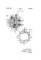
Figure 2 is an elevation of the pump, showing in part the Operating means.
Like parts are designated by like characters throughout specification and drawing.
A is a pump body or housing that is preferably provided in one face with a raised land A1 which co-operates to form a depression or pump chamber portion A2. A3 is a cavity formed in the lpump body A and provided adjacent one end With an inwardly extending shoulder or reduced portionA. An inlet valve housing may be seated in the cavity A3. A5 is another cavity formed in the body portion A and provided adjacent one end with a shoulder or reduced portion A5. An outlet valve housing may be positioned withvin the cavity A5 and may rest against the shoulder or reduced portion A5. Extending .through the body portion A and communicating with the pump chamber and with the outside of the pump is an air vent A7. A8 is a controlling valve there-e for, preferably provided with a handle .or manipulating part A by means of which it may be moved into and out of position to control'the air vent. The air vent, while it may be placed in any 'suitable location, is preferably in an extension' A1o formed as a part of the valve body.
Removably secured to the valve body A is a retaining portion B of generally annular shape. It may be fastened to the valve body by screws B1 or by any other suitable means.
Lying between the pump body A and the retaining member B and compressed against the land A1 of the pump body is a disc or diaphragm C. It, together with the pump body A, completes the pump chamber A2. This diaphragm may be 65 made of any suitable material and it serves 1930, Serial No. 489,747
merely as a sealing or closing member to complete the pump chamber. Positioned within the pump chamber or cavity A2 and bearing upon the portion A and upon the diaphragm C is a plurality of laminations C1 which, together, form an internal laminated spring. They are so shaped land proportioned that they tend to force the diaphragm C outward and do so whenever they are free to move.
supported from and preferably made integral with the retaining member B is a support D. This support is in effect a loop provided with oppositely placed parts which are fastened to the annulus B and 'provided with a portion joining these two, so that it thus provides a loop over the valve disc or diaphragm.
E is a compression plate positioned against the diaphragm, C.A It is provided with one generally fiat face which lies against the diaphragm and it is somewhat rounded or tapered away adjacent its edges as at E1. On its opposite face it carries a boss E2 and a helical race E3. Tapered rollers E4 are mounted to run in the helical race E3.
F is a rocking member provided with a depression F1 which is seated upon the boss E2. The rocking member is provided on one face with a helical race F2 and on its opposite side with a fiat race F'3 within which tapered rollers F4 are positioned and adapted to move. At one edge and extending outwardly from the rocking member F is a pair of ears F5, F5. Positioned between the ears is a drive rod or shaft F5 which may be moved by any suitable mechanism back and forth, as indicated by the arrow in Figure 2. F1 is a boss formed on the member F, opposite the depression F1.
G is a bearing supporting member resting upon the boss F7 of the member F and provided with a flat bearing race G1.- The member G rests against the support D.
H is an inlet valve housing adapted to be seated in the cavity A3 in the pump body A. It is provided with a bore H1 which has at one end a valve seat portion H2- H3 is a valve positioned within the bore H1 and carrying a head H4 adapted to be seated in the seat E2. A spring H5 bearing at one end upon the valve and at the other upon the laminations C1 tends to hold the valve seated.
I is an outletvalve housing provided with a bore I1 which terminates in a reduced portion P and has a seat I3 adjacent the reduced portion. 14 is a valve formed with a point 15. The valve is positioned within the bore I1 and the point is adapted to be seated in the seat 13. 15 is a spring tending normally to hold the valve seated. The valve housings may be held in the position shown by any suitable means, such for example as clamps, or they might be threaded into the valve body.
It will be realized that while I have herewith shown and described a practical operative device, nevertheless many changes might be made in the size, shape, number and disposition of parts without departing from the spirit of my invention and I wish, therefore, that my showing be taken as in a sense diagrammatic. Particularly the form of the housing and the means for compressing or moving the diaphragm might be widely changed, as might also particular structural details of the several other parts of the device.
The use and operation of the invention are as follows:
With the parts assembled as shown, it is assumed that the diaphragm or disc C is lying in a flat position and that fluid is within the pump chamber. A heavy and preferably sudden pressure is exerted upon the diaphragm to force it inward against resistance of the laminations C1L by movement of the shaft or rod FG, which movement causes the rocking member F to move and the compression member or washer E is forced against the diaphragm as a result of the motlon of the rocking member which turns through a portion of a revolution and causes the rollers which engage it to ride upon the helicalrace formed on the back of the member E and on the face of the rocking member F. The side of the rocking member away from the diaphragm has a fiat face which serves merely as a thrust bearing, the other face of which is formed by the member G. This movement of the rocking member F is imparted to the diaphragm C, as explained, and forces it inwardly against the resistance of the laminations C1, thus reducing the volume of the pump chamber, creating pressure Within it and forcing open the outlet valve and discharging fiuid from the pump.
. After the discharge stroke the rocking member is moved in the reverse direction and the member E is permitted to fall back from the diaphragm as a result of the reverse movement given the rocking member with its helical race. The diaphragm may then spring or move outwardly again under the influence of the laminations C1, thus increasing the vo'lume of the pump chamber, permitting or causing the outlet valve to close, creating a suction which opens the inlet valve and draws a fuel charge into the pump chamber. Thus a suction stroke is completed and the pump consists of the alternate compression and expansion or inward and outward movement of the diaphragm in response to the wedging action which is communicated to it by the movement of the rocking member F.
I claim:
1. In a pump, a pump housing and a fiexible diaphragm fixed to said housing in sealing contact and with it defining a pumping chamber, and a resistance member within the pump chamber, adapted to resist movement of the diaphragm and means for moving said diaphragm in opposition to the resistance of said resistance member, said means comprising a wedge, the resistance member comprising a laminated spring.
2. In a pump, a pump housing and a fiexible diaphragm fixed to said housing in sealing contact and with it defining a pumping chamber, and an approximately rigid resistance member within the pump chamber adapted to resist movement of the diaphragm and means for moving said diaphragm in opposition to the resistance of said approximately rigid resistance member, said means comprising a wedge.
3. In a pump, a pump housing and a fiexible diaphragm fixed to said housing in sealing contact and with it defining a pumping chamber, and a resistance member within the pump chamber comprising a laminated spring adapted to resist movement of the diaphragm and means for moving said diaphragm in opposition to the resistance of said resistance member, said means comprising a wedge, adapted to be moved to exert pressure upon said diaphragm.
4. In a pump, a pump housing and a fiexible diaphragm fixed to said housing in sealing contact and with it defining a pumping chamber, and a resistance member within the pump chamber comprising a laminated spring adapted to resist movement of the diaphragm and means for moving said diaphragm in opposition to the resistance of said resistance member, said means comprising a wedge positioned against and adapted to be moved to exert pressure upon said diaphragm.
5. In a pump, a pump housing and a fiexible diaphragm fixed to said housing in sealing contact and with it defining a pumping chamber, and a resistance member within the pump chamber adapted to resist movement of the diaphragm and means for moving said diaphragm in opposition to the resistance of said resistance member, said means comprising a wedge, said wedge carrying a helical race adapted to receive antifriction members.
6. In a pump, a pump housing and a fiexible diaphragm fixed to said housing in sealing contact and with it defining a pumping chamber, and an approximately rigid resistance member within the pump chamber, adapted to resist movement of the diaphragm and means for moving said diaphragm in opposition to the resistance of said approximately rigid resistance member, said means comprising a wedge positioned against said diaphragm, said wedge carrying a helical race adapted to receive anti-friction members.
7. In a pump, a pump housing and a fiexible diaphragm fixed to said housing in sealing contact and with it defining a pumping chamber, and a resistance member within the pump chamber adapted to resist movement of the diaphragm and means for moving said diaphragm in opposition to the resistance of said resistance member, said means comprising a wedge positioned against and adapted to be moved to exert pressure upon said diaphragm, said wedge carrying a helical race adapted to receive anti-friction members.
8. In a pump, a pump housing and a fiexible diaphragm fixed to said housing in sealing contact and with it defining a pumping chamber, and an approximately rigid resistance member within the pump chamber adapted to resist movement of the diaphragm and means for moving said diaphragm in opposition to the resistance of said approximately rigid resistance member, said means comprising a wedge positioned against and adapted to be moved to exert pressure upon said diaphragm, said wedge carrying a helical race adapted to receive anti-friction members.
9. In a pump, a pump housing and a fiexible diaphragm fixed to said housing in sealing contact and with it defining a pumping chamber,
and a resistance member within the pump chamber comprising a laminated spring adapted to resist movement of the diaphragm and means for moving said diaphragm in opposition to the resistance of said resistance member, said means comprising a wedge, and a member fixed with relation to the pump housing and mounted for co-operation with said Wedge.
10. In a pump, a pump housing and a fiexible diaphragm fixed to said housing in sealing contact and with it defining a pumping chamber, and a resistance member Within the pump chamber comprising a laminated spring adapted to resist movement of the diaphragm and means for moving said diaphragm in opposition to the resistance of said resistance member, said means comprising a wedge adapted to be moved to exert pressure upon said diaphragm, and a member fixed with relation to the pump housing and mounted for cooperation with said wedge.
11. In a pump, a pump housing and a flexible diaphragm fixed to said housing in sealing contact and with it defim'ng a pumping chamber, and a resistance member Within the pump chamber adapted to resist movement of the diaphragm and means for moving said diaphragm in opposition to the resistance of said resistance member, said means comprising a wedge adapted to be moved to exert pressure upon said diaphragm, said wedge carrying a helical race adapted to receive anti-friction members, and a member fixed with relation to the pump housing and mounted for co-operation with said wedge.
12. In a pump, a pump housing and a fiexible diaphragm fixed to said housing in seaiing contact and with it defining apumping chamber, and a resistance member within the pump chamber adapted to resist movement of the diaphragm and means for moving said diaphragmin opposition to the resistance of said resistance member, said means comprising a wedge positioned against and adapted to be moved to exert pressure upon said diaphragm, said wedge carrying a helical race adapted to receive anti-friction members, and a member fixed with relation to the pump housing and mounted for co-operation with said wedge.
13. In a pump, a pump housing and a fiexible diaphragm fixed to said housing in sealing contact and with it defining a pumping chamber, and a resistance member within the pump chamber comprising a laminated spring adapted to resist movement of the diaphragm and means for moving said diaphragm in opposition to the resistance of said resistance member, said means comprising a wedge and means for moving said wedge.
14. In a pump, a pump housing and a fiexible diaphragm fixed to said housing in sealing contact and with it defining a pumping chamber, and a resistance member within the pump chamber comprising a laminated spring adapted to resist movement of the diaphragm and means for moving said diaphragm in opposition to the resistance of said resistance member, said means comprising a wedge adapted to be moved to exert pressure upon said ldiaphragm, and means for moving said wedge.
15. InA a pump, a pump housing and a flexibie diaphragm fixed to said housing in sealing contact and with it defining a pumping chamber, and a. resistance member within the pump chamber adapted to resist movement of the diaphragm andmeans for moving said diaphragm in opposition to the resistance of said resistance member, said means comprising a wedge adapted to be moved to exert pressure upon said diaphragm, said wedge carrying a helicai race adapted to receive Vantifriction members, and means for moving said wedge.
16. In a pump, a pump housing and a fiexible diaphragm fixed to said housing in sealing contact and With it defining a pumping chamber, and an approximately rigid resistance member within the pump chamber adapted to resist movement of the diaphragm, and means for moving said diaphragm in opposition to the resistance of said approximately rigid resistance member, said means comprising a wedge positioned against and adapted to be moved to exert pressure upon said diaphragm, said wedge carrying a helical race -adapted to receive anti-friction members, and
means for moving said wedge.
PHILIP LANE SCOTT.
Priority Applications (1)
| Application Number | Priority Date | Filing Date | Title |
|---|---|---|---|
| US489747A US1978232A (en) | 1930-10-20 | 1930-10-20 | Pump |
Applications Claiming Priority (1)
| Application Number | Priority Date | Filing Date | Title |
|---|---|---|---|
| US489747A US1978232A (en) | 1930-10-20 | 1930-10-20 | Pump |
Publications (1)
| Publication Number | Publication Date |
|---|---|
| US1978232A true US1978232A (en) | 1934-10-23 |
Family
ID=23945109
Family Applications (1)
| Application Number | Title | Priority Date | Filing Date |
|---|---|---|---|
| US489747A Expired - Lifetime US1978232A (en) | 1930-10-20 | 1930-10-20 | Pump |
Country Status (1)
| Country | Link |
|---|---|
| US (1) | US1978232A (en) |
-
1930
- 1930-10-20 US US489747A patent/US1978232A/en not_active Expired - Lifetime
Similar Documents
| Publication | Publication Date | Title |
|---|---|---|
| US3137237A (en) | Pump sealing apparatus | |
| US6296460B1 (en) | Rotary cavity pump | |
| US3884598A (en) | Piston assembly for diaphragm pump | |
| GB1501328A (en) | Pump for pumping insulating fluid oil for electric cables | |
| US4486152A (en) | Pump with spring loaded valve | |
| US2809868A (en) | Fuel pump and fuel injector combination | |
| US3077204A (en) | Elastic ball check valve | |
| US3127845A (en) | Pump design | |
| US3285192A (en) | Pumps | |
| US2957420A (en) | Metering pump | |
| US1976415A (en) | Pump | |
| US1978232A (en) | Pump | |
| US3227094A (en) | High pressure hydraulic pumps | |
| US3601509A (en) | Electromagnetic pump | |
| US3975116A (en) | Pressure responsive fluid valve assembly | |
| US1973181A (en) | Pump | |
| US3030978A (en) | Pump valve structure | |
| US1692639A (en) | Pump | |
| US1538166A (en) | Force pump | |
| US2453929A (en) | Hydraulic pump | |
| US2254539A (en) | Fluid pump | |
| US2139571A (en) | Fuel pump | |
| DE3542454A1 (en) | Diaphragm rotary pump | |
| US3578879A (en) | Spring actuated fuel pump for fuel injection systems | |
| US3333543A (en) | Metering pump |