US1929249A - Vibratory screen - Google Patents
Vibratory screen Download PDFInfo
- Publication number
- US1929249A US1929249A US483176A US48317630A US1929249A US 1929249 A US1929249 A US 1929249A US 483176 A US483176 A US 483176A US 48317630 A US48317630 A US 48317630A US 1929249 A US1929249 A US 1929249A
- Authority
- US
- United States
- Prior art keywords
- screen
- side plates
- casings
- vibratory
- bridge member
- Prior art date
- Legal status (The legal status is an assumption and is not a legal conclusion. Google has not performed a legal analysis and makes no representation as to the accuracy of the status listed.)
- Expired - Lifetime
Links
Images

Classifications
-
- B—PERFORMING OPERATIONS; TRANSPORTING
- B07—SEPARATING SOLIDS FROM SOLIDS; SORTING
- B07B—SEPARATING SOLIDS FROM SOLIDS BY SIEVING, SCREENING, SIFTING OR BY USING GAS CURRENTS; SEPARATING BY OTHER DRY METHODS APPLICABLE TO BULK MATERIAL, e.g. LOOSE ARTICLES FIT TO BE HANDLED LIKE BULK MATERIAL
- B07B1/00—Sieving, screening, sifting, or sorting solid materials using networks, gratings, grids, or the like
- B07B1/28—Moving screens not otherwise provided for, e.g. swinging, reciprocating, rocking, tilting or wobbling screens
- B07B1/284—Moving screens not otherwise provided for, e.g. swinging, reciprocating, rocking, tilting or wobbling screens with unbalanced weights
Definitions
- the present invention relates in general to improvements in the art of separating fines from coarser materials, and relates more specifically to improvements in the construction and operation of screens of the vibratory type.
- An object of the invention is to provide a vibratory screen which is simple and compact in construction, and which is also efficient in operation.
- Another object of the invention is to provide a rigid screen structure which may be manufactured at minimum cost, and which may be maintained in effective operating condition with minimum diificulty.
- a further object of the invention is to provide improved mechanism for supporting and for producing vibration of a screen, and means for effecting convenient variation in the rate of screening by changing the extent of inclination and the degree of vibration of the screening surface.
- Still another object of the invention is to provide animproved screening mechanism which is self-contained and therefore readily transportable, and which may be readily installed and subsequently operated with minimum expenditure of power.
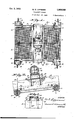
- Fig. l is a full top view of one of the improved vibratory screens
- Fig. 2 is a side elevation of the vibratory screen shown in Fig. 1;
- Fig. 3 is a transverse section through the vibratory screen, the section being taken along the line 3--3 of Fig. 1;
- Fig. 4 is an enlarged view of the driving motor, showing a central vertical section through the vibratory rotors associated with the motor;
- Fig. 5 is a similarly enlarged side view of the motor showing a transverse section through one of the vibrating rotors, the section being taken. along the line 55 of Fig. 4;
- Fig. 6 is an enlarged central vertical section through one of the resilient supports for the vibratory screen.
- Fig. 7 is a similarly enlarged section through the transverse bridge member of the screen, the section being taken along the line 77 of Fig. 3.
- the improved vibratory screen specifically shown in the drawings by way of illustration, comprises in general a perforated plate or wire mesh screen 9 having its opposite longitudinal edges secured to laterally spaced side plates 8, the screen 9 being adapted to be rapidly vibrated by means of one or more unbalanced rotors 12 operable at high speed by an electric motor 11 or the like.
- the side plates 8 which support the screen 9, may be formed of relatively stiff sheet metal and are rigidly interconnected above-the screen by means of a bridge member 10.
- the bridge member 10 is likewise preferably formed of sheet metal plate and has opposite end portions extending downwardly and coacting directly with the outer portions of the side plates 8 as clearly shown in Figs. 1, 2 and 3, in order to prevent spreading of the side plates 8.
- the medial portion of the bridge member 10 has U-shaped cross section as shown in Fig. 7, in order to provide a rigid beam which is well adapted for resisting collapse of the member and inward displacement of the side plates.
- the bridge member 10 may either be formed of a single plate, or it may be built up of a top plate 23 having downwardly bent integral ends, side plates 24 attached to the top plate 23 by means of angle bars 25, and stifiening angle bars 26 secured to the lower edges of the side plates 24, the ends of the angle bars 25, 26 also being bent downwardly and rigidly attached to the outer portions of the side plates 8. While only one bridge member located intermediate the ends of the plates 8, has been shown, it should be understood” that in longer screens 90 several of these bridge members may be utilized in order to enhance the rigidity of the structure.
- the side plates 8 are furthermore rigidly interconnected, below the screen 9, by means of one or more tubular elements 20, one of these elements being located at each end of the screen in the specific embodiment illustrated.
- the tubular elements 20 are rigidly attached at their ends to the side plates 8, and each of the elements 20 has a spring casing 16 of larger diameter than the element, associated with each end thereof.
- a longitudinal brace 31 may be utilized to interconnect the medial portions of the elements 20, a channel bar having been employed for this purpose in the specific embodiment illustrated.
- the various structural elements thus far described and constituting theframe for supporting the screen 9 may be rigidly united by welding, riveting, or otherwise, thus providing an extremely rigid and durable frame structure of simple construction.
- a supporting rod 17 Disposed centrally within each of the tubular elements 20 and spaced from the interior walls thereof, is a supporting rod 17 the ends of which extend beyond both, of the opposite ends of the corresponding tubular element 20 and through the spring casings 16 associated with these ends.
- Bushings 18 embrace the rods 17 within the spring casing 16, and the extreme outer ends of the rods 17 may be suspended from cables 19 or otherwise attached to a building or similar supporting structure so as to permit convenient variation of the inclination of the screen 9 as shown in Fig. 2.
- a spiral fiat spring 13 constituting a resilient cushion, is interposed between each bushing 18 and the corresponding spring casing 16, these springs snugly embracing the bushings 18 and likewise snugly fitting within the bores of the casings 16.
- the springs 13 are retained within the casings 16 by flanges 30 formed at the ends of the bushings 18 and the interiors of the bushings 18 may be lubricated through passages 29 formed in the ends of the rods 17, see Fig. 6.
- the spiral springs 13 should be so formed and disposed relative to the adjacent elements, that they will allow freedom of movement between the rods 1'7 and the tubular elements 20, thereby providing the necessary cushioning effect.
- the side edges thereof may be firmly attached to the lower side portionsof the side plates 8, by means of retainers or plates 14 having lower longitudinally extending hook portions engageable with the reversely bent side edges of the screen 9 as shown 14 so as to vary the tension on the screen 9.
- the mechanism specifically illustrated for vibrating the screen and its supporting frame comprises an electric motor 11 mounted directly upon the medial portion of the bridge member 10 and having an unbalanced rotor 12 secured directly to eaclr of the opposite ends of the motor shaft 32.
- Each of the rotors 12 has a number of segregated internal chambers 22 accessible through openings; which are normally sealed by pipe plugs 28.
- one or more of the chambers 22 may be supplied with a quantity of shot 21 as shown in Fig. 5.
- the vibratory screen built in accordancewith the present invention is extremely simple, compact and rigid in construction.
- the side plates 8 are rigidly interconnected both above and below the screen, by simple structural elements which may be manufactured at minimum cost.
- the unbalanced rotors l2 serve to effectively vibrate the screen to any desired extent, ,and while these elementshave been shown as being associated directly with the shaft 32 of the motor 11, such disposition of the rotors 12 is not necessary. It is, however, desirable to have the unbalanced rotors 12 mounted directly upon the screen supporting frame in order to insure most efficient transmission of the vibrations to the screening surface.
- the resilient supporting springs 13 provide simple and effective means for mounting the screen without undesirably cushioning the vibrations and without permitting undesirable transmission thereof to the building or other support, and the retaining plates 14 and adjusting bolts cooperating therewith provide simple and effective means for maintaining the screen 'I in position and for varying the tension thereon.
- the entire screen structure may obviously be transported 105 as a unit and may be conveniently installed and subsequently operated with minimum power expenditure.
- a screen elongated side plates secured to the opposite side edges of said screen, a single bridge member connecting said 120 side plates above the center of said screen, said bridge member having integral ends coacting with the outer sides of said plates to prevent spreading thereof away from said screen, a tubular element rigidly connecting each set of corresponding ends of said side plates below said screen, a cylindrical casing secured to each side plate adjacent each end of each tubular element, said casings being disposed concentric with the corresponding tubular elements, a spiral spring confined within each of said casings, suspension rods extending through said tubular elements and said casings and projecting beyond the latter, said rods coacting with said springs but being spaced from said tubular elements and said casings, and means for imparting vibration to said screen through said bridge member.
- a screen elongated side plates secured to the opposite side edges of said screen, a single bridge member connecting said side plates above the center of said screen, a tubular element rigidly connecting each set of corresponding ends of said side plates below said screen, a cylindrical casing secured to each side plate adjacent each end of each tubular element, said casings being disposed concentric with the corresponding tubular elements, a spiral spring confined within each of said casings, suspension rods extending through said tubular elements and said casings and projecting beyond the latter, said rods coacting with said springs but being spaced irom said tubular elements and said casings, and means for imparting vibration to said screen through said bridge member.
- a screen elongated side plates secured to the opposite side edges of said screen, a single bridge member connecting said side plates above the center, of said screemsaid bridge member having integral ends coacting with the outer sides of said plates to prevent spreading thereof away from said screen, a tubular element rigidly connecting each set of corresponding ends of said side plates belowfs'aid screen, a cylindrical casing secured to each side plate adjacent each end of each tubular element, a spiral spring confined within each of said casings, suspension rods extending through said tubular elements and said casings and projecting beyond the latter, said rods coacting with said springs but being spaced from said tubular elements and said casings, and means for imparting vibration to said screen through said bridge member.
- a screen elongated side plates secured to the opposite side edges of said screen, a single bridge member connecting said side plates above the center of said screen, a tubular element, rigidly connecting each set of corresponding ends of said side plates below said screen, a cylindrical casing secured to each side plate adjacent each end of each tubular element, a spiral spring confined within each of said casings, suspension rods extending through said tubular elements and said casing and projecting beyond the latter, said rods coacting with said springs but being spaced from said tubular elements and said casings, and means for imparting vibration to said screen through said bridge member.
- WALTER E. LIPPMANN LIPPMANN.
Description
VIBRATORY SCREEN Filed Sept. 20, 1930 2 Shedts-Sheet 1 INVENTOR.
ATTORNEYQ Oct. 3, 1933.
w. E. LKPPMANN 1,929,249
VIBRATORY SCREEN Fil pt. 20, 19:50 I Z'Sheets-SheQt 2 I .v. 1Q? INVENTOR- ii ni'ented not. 3, @333 1,929,249 VIBRATORY SCREEN Walter E. Lippmann, Milwaukee, Wis.
Application September 20, 1930 Serial No. 483,176
4 Claims.
The present invention relates in general to improvements in the art of separating fines from coarser materials, and relates more specifically to improvements in the construction and operation of screens of the vibratory type.
An object of the invention is to provide a vibratory screen which is simple and compact in construction, and which is also efficient in operation. Another object of the invention is to provide a rigid screen structure which may be manufactured at minimum cost, and which may be maintained in effective operating condition with minimum diificulty. A further object of the invention is to provide improved mechanism for supporting and for producing vibration of a screen, and means for effecting convenient variation in the rate of screening by changing the extent of inclination and the degree of vibration of the screening surface. Still another object of the invention is to provide animproved screening mechanism which is self-contained and therefore readily transportable, and which may be readily installed and subsequently operated with minimum expenditure of power. These and other more specific objects and advantages, will appear from the following detailed description.
A clear conception of an embodiment of the invention and of the mode of constructing and of operating screens built in accordance therewith, may be had by referring tothadrawings accompanying and forming a part of this specification, in which like reference characters designate the same or similar parts in the various views. 9
Fig. l is a full top view of one of the improved vibratory screens;
Fig. 2 is a side elevation of the vibratory screen shown in Fig. 1;
Fig. 3 is a transverse section through the vibratory screen, the section being taken along the line 3--3 of Fig. 1;
Fig. 4 is an enlarged view of the driving motor, showing a central vertical section through the vibratory rotors associated with the motor;
Fig. 5 is a similarly enlarged side view of the motor showing a transverse section through one of the vibrating rotors, the section being taken. along the line 55 of Fig. 4;
Fig. 6 is an enlarged central vertical section through one of the resilient supports for the vibratory screen; and
Fig. 7 is a similarly enlarged section through the transverse bridge member of the screen, the section being taken along the line 77 of Fig. 3.
The improved vibratory screen specifically shown in the drawings by way of illustration, comprises in general a perforated plate or wire mesh screen 9 having its opposite longitudinal edges secured to laterally spaced side plates 8, the screen 9 being adapted to be rapidly vibrated by means of one or more unbalanced rotors 12 operable at high speed by an electric motor 11 or the like.
, The side plates 8 which support the screen 9, may be formed of relatively stiff sheet metal and are rigidly interconnected above-the screen by means of a bridge member 10. The bridge member 10 is likewise preferably formed of sheet metal plate and has opposite end portions extending downwardly and coacting directly with the outer portions of the side plates 8 as clearly shown in Figs. 1, 2 and 3, in order to prevent spreading of the side plates 8. The medial portion of the bridge member 10 has U-shaped cross section as shown in Fig. 7, in order to provide a rigid beam which is well adapted for resisting collapse of the member and inward displacement of the side plates. The bridge member 10 may either be formed of a single plate, or it may be built up of a top plate 23 having downwardly bent integral ends, side plates 24 attached to the top plate 23 by means of angle bars 25, and stifiening angle bars 26 secured to the lower edges of the side plates 24, the ends of the angle bars 25, 26 also being bent downwardly and rigidly attached to the outer portions of the side plates 8. While only one bridge member located intermediate the ends of the plates 8, has been shown, it should be understood" that in longer screens 90 several of these bridge members may be utilized in order to enhance the rigidity of the structure.
The side plates 8 are furthermore rigidly interconnected, below the screen 9, by means of one or more tubular elements 20, one of these elements being located at each end of the screen in the specific embodiment illustrated. The tubular elements 20 are rigidly attached at their ends to the side plates 8, and each of the elements 20 has a spring casing 16 of larger diameter than the element, associated with each end thereof. A longitudinal brace 31 may be utilized to interconnect the medial portions of the elements 20, a channel bar having been employed for this purpose in the specific embodiment illustrated. The various structural elements thus far described and constituting theframe for supporting the screen 9 may be rigidly united by welding, riveting, or otherwise, thus providing an extremely rigid and durable frame structure of simple construction.
Disposed centrally within each of the tubular elements 20 and spaced from the interior walls thereof, is a supporting rod 17 the ends of which extend beyond both, of the opposite ends of the corresponding tubular element 20 and through the spring casings 16 associated with these ends. Bushings 18 embrace the rods 17 within the spring casing 16, and the extreme outer ends of the rods 17 may be suspended from cables 19 or otherwise attached to a building or similar supporting structure so as to permit convenient variation of the inclination of the screen 9 as shown in Fig. 2. A spiral fiat spring 13 constituting a resilient cushion, is interposed between each bushing 18 and the corresponding spring casing 16, these springs snugly embracing the bushings 18 and likewise snugly fitting within the bores of the casings 16. The springs 13 are retained within the casings 16 by flanges 30 formed at the ends of the bushings 18 and the interiors of the bushings 18 may be lubricated through passages 29 formed in the ends of the rods 17, see Fig. 6. The spiral springs 13 should be so formed and disposed relative to the adjacent elements, that they will allow freedom of movement between the rods 1'7 and the tubular elements 20, thereby providing the necessary cushioning effect.
When a wire mesh screen 9 is utilized, the side edges thereof may be firmly attached to the lower side portionsof the side plates 8, by means of retainers or plates 14 having lower longitudinally extending hook portions engageable with the reversely bent side edges of the screen 9 as shown 14 so as to vary the tension on the screen 9. By
tightening up on the bolts 15, the tension on the screen 9 may obviously be increased, whereas loosening of these bolts will tend to decrease the screen tension.
The mechanism specifically illustrated for vibrating the screen and its supporting frame, comprises an electric motor 11 mounted directly upon the medial portion of the bridge member 10 and having an unbalanced rotor 12 secured directly to eaclr of the opposite ends of the motor shaft 32. Each of the rotors 12 has a number of segregated internal chambers 22 accessible through openings; which are normally sealed by pipe plugs 28. Depending upon the degree of vibratory motion desired, one or more of the chambers 22 may be supplied with a quantity of shot 21 as shown in Fig. 5. Due to the eccentric weighting of the rotors 12 and the high speed of rotation thereof, these rotors will produce rapid vibratory movement of the screen and the extent of this vibratory movement may readily be varied by varying the quantity of shot confined within each of the. rotors 12. I
While normal operation of the screen should be clearly apparent from the foregoing descripof the screen, gradually advances toward the terial passing through the screen perforations, and the coarser material eventually being delivered over the discharge edge of the screen.
From the foregoing description it will be apparent that the vibratory screen built in accordancewith the present invention is extremely simple, compact and rigid in construction. The side plates 8 are rigidly interconnected both above and below the screen, by simple structural elements which may be manufactured at minimum cost. The unbalanced rotors l2 serve to effectively vibrate the screen to any desired extent, ,and while these elementshave been shown as being associated directly with the shaft 32 of the motor 11, such disposition of the rotors 12 is not necessary. It is, however, desirable to have the unbalanced rotors 12 mounted directly upon the screen supporting frame in order to insure most efficient transmission of the vibrations to the screening surface. The resilient supporting springs 13 provide simple and effective means for mounting the screen without undesirably cushioning the vibrations and without permitting undesirable transmission thereof to the building or other support, and the retaining plates 14 and adjusting bolts cooperating therewith provide simple and effective means for maintaining the screen 'I in position and for varying the tension thereon. The entire screen structure may obviously be transported 105 as a unit and may be conveniently installed and subsequently operated with minimum power expenditure.
It should be understood that it is not desired to limit the invention to the exact details of 110 construction and to the precise mode of operating vibratory screens, herein shown and described, for various modifications within the scope of the claims may occur to persons skilled in the art.
It is claimed and desired to secure by Letters Patent:
1. In combination, a screen, elongated side plates secured to the opposite side edges of said screen, a single bridge member connecting said 120 side plates above the center of said screen, said bridge member having integral ends coacting with the outer sides of said plates to prevent spreading thereof away from said screen, a tubular element rigidly connecting each set of corresponding ends of said side plates below said screen, a cylindrical casing secured to each side plate adjacent each end of each tubular element, said casings being disposed concentric with the corresponding tubular elements, a spiral spring confined within each of said casings, suspension rods extending through said tubular elements and said casings and projecting beyond the latter, said rods coacting with said springs but being spaced from said tubular elements and said casings, and means for imparting vibration to said screen through said bridge member.
2. In combination, a screen, elongated side plates secured to the opposite side edges of said screen, a single bridge member connecting said side plates above the center of said screen, a tubular element rigidly connecting each set of corresponding ends of said side plates below said screen, a cylindrical casing secured to each side plate adjacent each end of each tubular element, said casings being disposed concentric with the corresponding tubular elements, a spiral spring confined within each of said casings, suspension rods extending through said tubular elements and said casings and projecting beyond the latter, said rods coacting with said springs but being spaced irom said tubular elements and said casings, and means for imparting vibration to said screen through said bridge member.
3. In combination, a screen, elongated side plates secured to the opposite side edges of said screen, a single bridge member connecting said side plates above the center, of said screemsaid bridge member having integral ends coacting with the outer sides of said plates to prevent spreading thereof away from said screen, a tubular element rigidly connecting each set of corresponding ends of said side plates belowfs'aid screen, a cylindrical casing secured to each side plate adjacent each end of each tubular element, a spiral spring confined within each of said casings, suspension rods extending through said tubular elements and said casings and projecting beyond the latter, said rods coacting with said springs but being spaced from said tubular elements and said casings, and means for imparting vibration to said screen through said bridge member.
4. In combination, a screen, elongated side plates secured to the opposite side edges of said screen, a single bridge member connecting said side plates above the center of said screen, a tubular element, rigidly connecting each set of corresponding ends of said side plates below said screen, a cylindrical casing secured to each side plate adjacent each end of each tubular element, a spiral spring confined within each of said casings, suspension rods extending through said tubular elements and said casing and projecting beyond the latter, said rods coacting with said springs but being spaced from said tubular elements and said casings, and means for imparting vibration to said screen through said bridge member. WALTER E. LIPPMANN.
Priority Applications (1)
| Application Number | Priority Date | Filing Date | Title |
|---|---|---|---|
| US483176A US1929249A (en) | 1930-09-20 | 1930-09-20 | Vibratory screen |
Applications Claiming Priority (1)
| Application Number | Priority Date | Filing Date | Title |
|---|---|---|---|
| US483176A US1929249A (en) | 1930-09-20 | 1930-09-20 | Vibratory screen |
Publications (1)
| Publication Number | Publication Date |
|---|---|
| US1929249A true US1929249A (en) | 1933-10-03 |
Family
ID=23918974
Family Applications (1)
| Application Number | Title | Priority Date | Filing Date |
|---|---|---|---|
| US483176A Expired - Lifetime US1929249A (en) | 1930-09-20 | 1930-09-20 | Vibratory screen |
Country Status (1)
| Country | Link |
|---|---|
| US (1) | US1929249A (en) |
Cited By (2)
| Publication number | Priority date | Publication date | Assignee | Title |
|---|---|---|---|---|
| US3014587A (en) * | 1959-08-24 | 1961-12-26 | Syntron Co | Vibratory screen with single unbalanced vibratory motor |
| US3989621A (en) * | 1974-06-14 | 1976-11-02 | The Cleveland Vibrator Company | Vibratory screener |
-
1930
- 1930-09-20 US US483176A patent/US1929249A/en not_active Expired - Lifetime
Cited By (2)
| Publication number | Priority date | Publication date | Assignee | Title |
|---|---|---|---|---|
| US3014587A (en) * | 1959-08-24 | 1961-12-26 | Syntron Co | Vibratory screen with single unbalanced vibratory motor |
| US3989621A (en) * | 1974-06-14 | 1976-11-02 | The Cleveland Vibrator Company | Vibratory screener |
Similar Documents
| Publication | Publication Date | Title |
|---|---|---|
| US4361240A (en) | Material separating machine | |
| AU2003241634A1 (en) | Multi-deck screening machine | |
| US2246483A (en) | dillon | |
| US2153243A (en) | Vibratory screen | |
| US1929249A (en) | Vibratory screen | |
| US3087617A (en) | Screener | |
| AU2013200433A1 (en) | Flip-flow screen | |
| US3317041A (en) | Resonant screen | |
| US2208596A (en) | Reciprocating screen | |
| US1705619A (en) | Vibrating screen | |
| US1923229A (en) | Screening apparatus | |
| US2225909A (en) | Screen | |
| US2137753A (en) | Vibratory screening device | |
| US1397342A (en) | Assictob to stubte | |
| US2069331A (en) | Vibratory screen | |
| US2579002A (en) | Mechanical vibrating screen | |
| US440883A (en) | Gravity-scalper | |
| WO1993024245A1 (en) | Vibratory screening apparatus | |
| US2176376A (en) | Inclined vibrating screen | |
| US2597503A (en) | Shaking screen | |
| US2453883A (en) | Vibratory screen | |
| US2102826A (en) | Vibratory apparatus | |
| US1397338A (en) | Screen-separator | |
| US2112886A (en) | Screening device | |
| US1565883A (en) | Screen |