US192575A - Improvement in grain-binders - Google Patents
Improvement in grain-binders Download PDFInfo
- Publication number
- US192575A US192575A US192575DA US192575A US 192575 A US192575 A US 192575A US 192575D A US192575D A US 192575DA US 192575 A US192575 A US 192575A
- Authority
- US
- United States
- Prior art keywords
- arm
- grain
- platform
- binding
- rake
- Prior art date
- Legal status (The legal status is an assumption and is not a legal conclusion. Google has not performed a legal analysis and makes no representation as to the accuracy of the status listed.)
- Expired - Lifetime
Links
- 239000011230 binding agent Substances 0.000 title description 26
- 239000002184 metal Substances 0.000 description 16
- 241001589086 Bellapiscis medius Species 0.000 description 10
- 241001384313 Hydrocryphaea Species 0.000 description 4
- 238000010276 construction Methods 0.000 description 4
- 210000003165 Abomasum Anatomy 0.000 description 2
- 235000009825 Annona senegalensis Nutrition 0.000 description 2
- VKYKSIONXSXAKP-UHFFFAOYSA-N Hexamethylenetetramine Chemical compound C1N(C2)CN3CN1CN2C3 VKYKSIONXSXAKP-UHFFFAOYSA-N 0.000 description 2
- 239000000969 carrier Substances 0.000 description 2
- 210000001699 lower leg Anatomy 0.000 description 2
- 229920000136 polysorbate Polymers 0.000 description 2
- 230000001105 regulatory Effects 0.000 description 2
- 230000000630 rising Effects 0.000 description 2
Images


Classifications
-
- A—HUMAN NECESSITIES
- A01—AGRICULTURE; FORESTRY; ANIMAL HUSBANDRY; HUNTING; TRAPPING; FISHING
- A01D—HARVESTING; MOWING
- A01D39/00—Independent binders, e.g. for hay; Binders attachable to mowers
Definitions
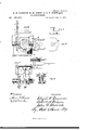
- FIG. 4 a rear view, showing the devices for swinging the platform, and devices for operating the binder;
- Fig. 5 a side view of the same, with the lower portion of the frame broken away;
- Fig. 6, a front elevation of the devices for operating the binding and rake arms;
- Fig. 7, a top or plan view of the same devices, with a portion of the frame broken away;
- Figs. 8, 9, and l0 details of the stirrup or fra-me for connecting the lever with the receiving-platform and supporting part of the driving devices.
- Figs. 6, 7, 8, 9, and l0 are enlarged.
- This invention relates to that class of grainbinders in which the grain is received upon a platform and then bound automatically.
- the binding mechanism proper should be so constructed that it can be adjusted to the length of the grain to be bound, and that the grain should be brought in a compact form to the binding mechanism.
- the devices for accomplishing the forward and back adjustment of the binder to the length of the grain have been such that the entire binding mechanism would have to be moved forward or back.
- the object of our invention is to provide a simple and efficient method of getting the grain from the receptacle to the binding mechanism; to provide a simple method of bringing the gavel to any required position in relation to the binding-wire preparatory to receiving the same; to provide a method for preventing slack wire from paying off the spool as the needle is withdrawn from the twisting mechanism, and to improve the construction and operation of the devices employed.
- Its nature consists in arranging the binding-arm so that it will operate in correct relation to the twisting-hook under all circumstances; in
- A represents the main frame; B, the elevator-frame; B', the upper elevator-roller; C, the cross-bars ot' the elevator-frame, on which the drivers platform is secured; C', the drivers platform.
- D is a pivoted board or cross-bar or platform located above the bars C, as shown, upon which the binding mechanism is mounted, forming the outer portion of the receivingplatform.
- D is a metal plate secured to the platform D, and forming the remaining portion of the receiving-platform.
- E is an inclined sliding board, connected with the plate Dl by any suitable means, and located on the elevator frame beneath the roller B.
- the connection between E and D' must be such that the plate D can pass under the board.
- the upper portion of this frame is curved and bent over and downward,
- G is a rock-shaft, having its bearingsin the lower end of the curved portion of F in suitable boxes.
- H is a reciprocating needle-arm, secured at its lower end to the rock-shaft G by means of a hub, so that the arm can move up and down, and the shaft turn in the said hub.
- I is a metal arm or bar, pivoted in the rockshaft G, so that it has both a reciprocating and a horizontal movement.
- J is a metal tooth, pointed at its lower end to facilitate its entering the grain and permanently or adjustably secured at its upper end, near the outer end of the bar I.
- ametal bar pivoted at its lower end to the binding-arm H, at a point a little forward of its connection to the rock-shaft G.
- the upper end of this bar a is provided with a series ofholes, as shown, for adjusting the movement of the arm.
- b is -a straight bar, pivoted at its inner end to the upper end of the bar a, and it is provided at its inner end with a series of holes.
- c is a vertical metal bar, pivoted at its lower end to the outer end of a short lever, e', which lever, at its inner end, is permanently secured to the rock-shaft G.
- the upper end of this bar c is pivoted to the upper end of the bar a, the same pivot answering for connecting a, b, and c. It is also provided with a series of holes, as shown.
- d is a standard or post, suitably secured to the frame F, to the upper end of which the outer end of the bar b is pivoted.
- e is the enlarged portion of the rock-shaft G. Through an opening in this the arm I passes, and in which it is pivoted.
- e is the lever, to which the bar c is pivoted at its lower end, which lever is permanently secured to Gr.
- g is a socket, formed on, or permanently secured to, the wheel S, in which the end of f is inserted.
- 71 is a metal plate or arm, secured to the tooth J near its top, and extending out at the side thereof', and so arranged that when the rake-arm I is down and moving forward it will come in contact with the grain and prevent it from getting above the point of arm Hwhen delivered for binding, and also acts asa compressor.
- i is a metal prong or arm, secured to the arm I, back of the tooth J, so arranged that it will enter the grain ou the platform and aid the tooth J in carrying it forward, and also keeping the gavel in line while the grain is being moved to the binder.
- j is the wire-spool, constructed in any of the well-known forms. It is supported upon the rake-arm I by means of a suitable bracket, that may be made adjustable, to determine the length of wire, and it is so arranged in relation to the twisting-hook that the return movement of the rake-arm I will unwind just wire enough to bind a bundle, so that no slack wire is left after the bundle is bound, but the wire is drawn off from the sp ol only as it is required for binding the bundle.
- k is the pivot on which the receiving-platform is Supported and turned. It is made of considerable diameter, in order to furnish sufcient bearing-surface to keep the platform in position.
- k' is a slot on the under side of D, fitting over the top of the pivot k, and serving the purpose of a guide for keeping the platform or table in position on the pivot.
- Z are flanges on the bottom of the pivot k, by means of which it is secured to cross-pieces, which cross-pieces are secured to the crosspieces C.
- m is a plate, secured to the top of one of the flanges l, and projecting out therefrom.
- n is a metal plate, secured to the under side of the cross-piece o, which piece is secured beneath the platform D. o is hollowed out on its front edge, so that the plate n projects. beyond it, and this plate is so arranged that the plate m comes in contact therewith, and holds the receiving-platform in place at that point.
- the pivot k is so located that the rear end 0f the table or platform describes a larger arc than the front, and its location is such, in reference to the point where the binding-arm descends, that iu whichever direction the table may be thrown the binding-arm will descend at the same point.
- p is a slot in the table or platform D D, into which the tooth J enters when mowing the grain. It is somewhat curved, as shown in Fig. 1.
- p is a slot in the sliding board E, formin a continuation of the slot p, but somewhat wider than the slot lo, to permit the entrance of the tooth at the beginning of the forward movement of the rake-arm.
- K is a hand-lever, pivoted near or around the shaft of the wheel N, and extending up so that its upper end is within reach of the driver when mounted on the platform C.
- L is a rod, connecting the lever K with the receiving-platform, as shown.
- One end of this rod is secured to the lever by means of the shaft for the upper pulley-wheel, and the other end issecured around a collar on the axle of the pulley-wheel on the receiving-platform.
- M are ears or bearings secured permanently to the frame or standard E.
- N N N N are pulley-wheels, by means of which motion is imparted to the binding and raking devices.
- the lower wheel N is secured, as shown, to a shaft, which shaft is supported in suitable bearings secured to the main frame, and to which the lower end of the lever K is connected.
- the inner end of this shaft is provided with a pinion, which is to engage with a similar wheel operated from the main or drive wheel, (not shown,) and drives the pulley-wheel N 5 or N may be provided with a suitable crank, through which power may be applied.
- the pulley-wheel N is journaled on the lever K, and is provided with two grooves in itsface. By locating the axis of the wheel N on the lever K, as shown, any change in the position of the lever will not affect the relative positions of the pulleywheels when the drive chains or belts are in place, so that the wheels will operate in whatever position they may be placed.
- the pulley-wheel N is located on the receiving-platform on the same shaft or axle to which the pinion for driving the wheel which operates the binding devices is secured.
- 0 is the driving chain or belt passing over the pulleys N N.
- P is the driving chain or belt passing over thepulleys NN, O being in the inner groove of the pulley N', and P in the outer.
- R is a stirrup or frame, pivoted to the ears M, so that it is free to turn in one direction.
- B. is a collar, permanently secured to the stirrnp-piece R, near its center, which collar forms a bearing or support for the axle of the pulley-wheel N" and pinion T.
- S is a gear-wheel, suitably journaled to the frame or support F, and through which inotion is givento the binding arm and rake, thevrake-arm being connected therewith, as before described, by means of the socket g and extension f, for this purpose.
- T is the pinion for driving the wheel S. Motion is given to this pinion through the pulley-wheels N N N, as before described.
- g is a link or hook, by means of which the sliding board E and receiving-platform are connected together. Other devices may be used for this purpose.
- r is the twisting-hook, located in a suitable bearing on the platform D, and so arranged in relation to the pivot that it willl remain nearly in a stationary position, its location for this purpose being at or near the center of the pivot.
- This location of the hook must also be such that the descent of the needle will bring the binding-wire close enough to the hook to be grasped thereby.
- s is a hole in the point of the needle.
- the twisting-hook is operated by means of a suitable gearing, and a cutter for severing the wire after the bundle is bound is to be provided, which cutter is to be so arranged that it will sever the wire between the bundle and hook, so as to leave the main wire coiled around the shank of the hook.
- the arrangement of the parts for operating the needle-arm is such that, when the rakearm has made its delivery-movement and commeuced to ascend, the needle-arm will commence to descend, so that when the rake has raised far enough to clear the gavel to be bound the needle arm has descended far enough to take the place of the tooth p, and hold the bundle in position until bound.
- the rake By constructing and attaching the rake as shown and described it has both a free vertical movement, by means of the rock-shaft Gr, and a horizontal movement, by means of its pivotal connection, so that on entering the the grain it will be driven straight through, and will cut the grain off in such a manner that the amount required for a bundle will be separated entirely from the remainder of the grain, the rake tooth p thus serving the purpose of a separator, as well as for carrying the grain forward to the twisting-hook.
- the rake and needle are in the position they occupy when the bundle is being bound, in which position the extension or arm f of the arm I is at its lowest point, as this f is carried around by the movement of the wheel S.
- the arm I will be carried up and over toward the elevator, and this movement will continue until the lever f is carried to its farthest horizontal position away from the elevator.
- This movement will bring the bar L into contact with the grain on the platform, and compress it so as to facilitate its being carried forward, and also compressing it compactly, and so that it can be moved with certainty to the position for bindward with lts tooth J in the slot l', carrying with it the grain for the bundle on the platform D', and this movement will continue until the crank f has reached a horizontal position nearest the elevator, during which movement of the crank the arm I described a circle similar in form to that described by it in its first movement, so that when the crank has reached a horizontal position opposite to that first described, the arm I has been withdrawn from the slot l, at which time the grain for the bundle has been forced against the binding-wire, and carried beyond the line of the twistin g-hook, which operation partially encircles the bundle by the binding-wire.
- the lever e has reached a nearly-level position, so that the points of the tooth J and the needle are just above the receivingplatform, and in a line with each other.
- the rake-arm is carried up the needle-arm is carried down, taking its position back of the bundle, keeping the bundle in position, carrying the binding-wire with it into the opening or slot l, and completing the encircling of the bundle by the wire.
- the twisting-hook is put into operation, twisting the two strands of wire together, and completing the-binding.
- the wire is then to be severed by a suitable cutlter, when the bundle drops upon the ground or into a suitable receptacle.
- the rake-arm ascends by the movement of the crank f, as first described, and when the needle has reached its farthest point of descent the rake will have been carried up and over to the carrier ready to descend and carry forward another bundle, during which descent the needle-arm will have ascended ready to pass down and tie the bundle carried forward by the next movement of the rake, and this operation will be repeated and continue as long as the ma chine is kept in motion.
- the driver moves the lever away from him, which4 carries the rear end of the binding-platform away from the elevator and carries the slot l l farther back, so that the tooth J will enter the grain at a point farther back.
- the rake has a wide range forward and back, and at the same time will bring the grain to the same point relative to the binding devices.
- the table or receiving-platform is made in two pieces; but it could be made of one piece, if desired, and the backboard E of the receiver may be dispensed with in various forms of elevators.
- the holes in the curved arms a, c and lever b are for the purpose of regulating the throw of the needle.
- the lever K is held in position by means of the brace-rod Q secured to the elevator-frame, as shown.
- the bindingarm H supported upon the swinging receiver or table D, in combination with a centrally-located twister and a rake, substantially as described.
- the yielding finger in combinationv with the arm I, for preventing the grain from getting abo ve-the point of the arm H while being carried forward, substantially as specified.
- the sliding backboard E located be-- tween the upper elevator-roller and the receiver, in combination with av horizontallyswinging receiving-platform, and a connecting device between said baokboard and platform for keeping the slots in line, substantial-
Description
4 Sheets-Sheet Z.
3.11. GAMMON, n. H. mm1 &, sur. sTEWARn.
GRAIN-BINDER. No. 192,575. Patented .Tu1y 3,1877.
MFETERS. PHOTO IJTHDGUFAER VIASHINCTDN D C 4Sheets-Sheet 3. 3.1i. GAMMON,R.H.DIXON & J'. F. STEWARID.
i GRAIN-BINDER. No, 192,575, Patented July 3,1877.
Maw
N.FETERS. FNOTO-LITMOGRAPHER. wASHlHGTnN, Dy c,
y dfsheets-Shet-. E. H. GAMMON, R. H. 'DIXON & J'. F. STEWARD. GRA:N-BINIJER.v
No. 192,575, Patented July 3,1877.
! Illu.. Illlllll.. /xlllin l II-lllllil XVM ELIJAH' H. GAMMON, OF CHICAGO, AND ROBERT H. DIXON AND JOHN F.
STEWARD, OF PLAN O, ASSIGNORS TO ELIJAH H. GAMMON AND WILLIAM DEERING, OF CHICAGO, ILLINOIS.
IMPROVEMENT IN GRAIN-BINDERS.
Speciication forming part of Letters Patent No. 192,575, dated July 3, 1877 application led May 25, 1877.
To all whom 'it may concern:
Be it known that we, ELIJAH H. GAMMQN, of the city of Chicago, Cook county, State of Illinois, and ROBERT H. DIXON and JoHNF. STEWARD, of Plano, Kendall county, State of Illinois, have invented new and useful Improvements in Grain-Binders, of which the following is a full description, reference being had to the accompanying drawings, consisting of four sb eets, in which- Figure l is a top or plan view, showing the receiving platform in position for ordinary binding; Fig. 2, a top or plan view, showing the receiving-platform in position for binding long grain; Fig. 3, a bottom view of the receiving-platform, with a portion broken away; Fig. 4, a rear view, showing the devices for swinging the platform, and devices for operating the binder; Fig. 5, a side view of the same, with the lower portion of the frame broken away; Fig. 6, a front elevation of the devices for operating the binding and rake arms; Fig. 7, a top or plan view of the same devices, with a portion of the frame broken away; Figs. 8, 9, and l0, details of the stirrup or fra-me for connecting the lever with the receiving-platform and supporting part of the driving devices.
Figs. 6, 7, 8, 9, and l0 are enlarged.
This invention relates to that class of grainbinders in which the grain is received upon a platform and then bound automatically. In such class of binders it is'necessary that the binding mechanism proper should be so constructed that it can be adjusted to the length of the grain to be bound, and that the grain should be brought in a compact form to the binding mechanism.
As heretofore constructed, the devices for accomplishing the forward and back adjustment of the binder to the length of the grain have been such that the entire binding mechanism would have to be moved forward or back.
It also relates to the machine shown and described in the application of John F. Steward, of even date herewith, to which machine the improvements described are more particularly applicable.
The object of our invention is to provide a simple and efficient method of getting the grain from the receptacle to the binding mechanism; to provide a simple method of bringing the gavel to any required position in relation to the binding-wire preparatory to receiving the same; to provide a method for preventing slack wire from paying off the spool as the needle is withdrawn from the twisting mechanism, and to improve the construction and operation of the devices employed. Its nature consists in arranging the binding-arm so that it will operate in correct relation to the twisting-hook under all circumstances; in
providing a secondary arm or rake mounted on the platform for forcing the grain forward to the twisting and tying devices; in providing such rake with a compressor-arm to hold the grain in place while being carried to the binder; in locating the spool which carries the binding-wire upon the secondary arm or rake so that the return movement of the arm will unwind the wire; in the arrangement of devices for swinging thereceiving-platform to adjust it to the length of grain; in devices for operating the binding arm and rake from the same driving mechanism; and in the several parts and combination of vparts hereinafter described and claimed as new.
In the dra-wings, A represents the main frame; B, the elevator-frame; B', the upper elevator-roller; C, the cross-bars ot' the elevator-frame, on which the drivers platform is secured; C', the drivers platform.
These parts, A, B, B', C,'and C', are of any of the ordinary forms of constructing such parts, except that the cross-bars C are extended somewhat farther to the rear; and the machine' is to be provided with a drive-wheel, carrier-platform, divider, grain -whe'el, sickle, and devices for operating the sickle, reel, and other parts, as usual; but, as such parts may be of any well-known form of construction, they are not shown or described.
D is a pivoted board or cross-bar or platform located above the bars C, as shown, upon which the binding mechanism is mounted, forming the outer portion of the receivingplatform.
D is a metal plate secured to the platform D, and forming the remaining portion of the receiving-platform.
E is an inclined sliding board, connected with the plate Dl by any suitable means, and located on the elevator frame beneath the roller B. The connection between E and D' must be such that the plate D can pass under the board.
Fis a metal standard or frame, located at the rear end of the platform D, to' which it is rigidly secured. The upper portion of this frame is curved and bent over and downward,
.so as to form a guard to protect the operating devices located on the frameF, and also to form a support for the needle-arm and rake.
G is a rock-shaft, having its bearingsin the lower end of the curved portion of F in suitable boxes.
H is a reciprocating needle-arm, secured at its lower end to the rock-shaft G by means of a hub, so that the arm can move up and down, and the shaft turn in the said hub.
I is a metal arm or bar, pivoted in the rockshaft G, so that it has both a reciprocating and a horizontal movement.
J is a metal tooth, pointed at its lower end to facilitate its entering the grain and permanently or adjustably secured at its upper end, near the outer end of the bar I.
ais ametal bar, pivoted at its lower end to the binding-arm H, at a point a little forward of its connection to the rock-shaft G. The upper end of this bar a is provided with a series ofholes, as shown, for adjusting the movement of the arm.
b is -a straight bar, pivoted at its inner end to the upper end of the bar a, and it is provided at its inner end with a series of holes.
c is a vertical metal bar, pivoted at its lower end to the outer end of a short lever, e', which lever, at its inner end, is permanently secured to the rock-shaft G. The upper end of this bar c is pivoted to the upper end of the bar a, the same pivot answering for connecting a, b, and c. It is also provided with a series of holes, as shown.
d is a standard or post, suitably secured to the frame F, to the upper end of which the outer end of the bar b is pivoted. e is the enlarged portion of the rock-shaft G. Through an opening in this the arm I passes, and in which it is pivoted.
e is the lever, to which the bar c is pivoted at its lower end, which lever is permanently secured to Gr.
fis a rearward extension of the arm I, forming a crank or lever, by means of which motion is imparted to the arms l and H by the wheel S.
g is a socket, formed on, or permanently secured to, the wheel S, in which the end of f is inserted.
71, is a metal plate or arm, secured to the tooth J near its top, and extending out at the side thereof', and so arranged that when the rake-arm I is down and moving forward it will come in contact with the grain and prevent it from getting above the point of arm Hwhen delivered for binding, and also acts asa compressor.
i is a metal prong or arm, secured to the arm I, back of the tooth J, so arranged that it will enter the grain ou the platform and aid the tooth J in carrying it forward, and also keeping the gavel in line while the grain is being moved to the binder.
j is the wire-spool, constructed in any of the well-known forms. It is supported upon the rake-arm I by means of a suitable bracket, that may be made adjustable, to determine the length of wire, and it is so arranged in relation to the twisting-hook that the return movement of the rake-arm I will unwind just wire enough to bind a bundle, so that no slack wire is left after the bundle is bound, but the wire is drawn off from the sp ol only as it is required for binding the bundle.
k is the pivot on which the receiving-platform is Supported and turned. It is made of considerable diameter, in order to furnish sufcient bearing-surface to keep the platform in position.
k' is a slot on the under side of D, fitting over the top of the pivot k, and serving the purpose of a guide for keeping the platform or table in position on the pivot.
Z are flanges on the bottom of the pivot k, by means of which it is secured to cross-pieces, which cross-pieces are secured to the crosspieces C.
m is a plate, secured to the top of one of the flanges l, and projecting out therefrom.
n is a metal plate, secured to the under side of the cross-piece o, which piece is secured beneath the platform D. o is hollowed out on its front edge, so that the plate n projects. beyond it, and this plate is so arranged that the plate m comes in contact therewith, and holds the receiving-platform in place at that point.
The pivot k is so located that the rear end 0f the table or platform describes a larger arc than the front, and its location is such, in reference to the point where the binding-arm descends, that iu whichever direction the table may be thrown the binding-arm will descend at the same point.
p is a slot in the table or platform D D, into which the tooth J enters when mowing the grain. It is somewhat curved, as shown in Fig. 1. v
p is a slot in the sliding board E, formin a continuation of the slot p, but somewhat wider than the slot lo, to permit the entrance of the tooth at the beginning of the forward movement of the rake-arm.
K is a hand-lever, pivoted near or around the shaft of the wheel N, and extending up so that its upper end is within reach of the driver when mounted on the platform C.
L is a rod, connecting the lever K with the receiving-platform, as shown. One end of this rod is secured to the lever by means of the shaft for the upper pulley-wheel, and the other end issecured around a collar on the axle of the pulley-wheel on the receiving-platform.
M are ears or bearings secured permanently to the frame or standard E.
N N N are pulley-wheels, by means of which motion is imparted to the binding and raking devices. The lower wheel N is secured, as shown, to a shaft, which shaft is supported in suitable bearings secured to the main frame, and to which the lower end of the lever K is connected.
The inner end of this shaft, as shown, is provided with a pinion, which is to engage with a similar wheel operated from the main or drive wheel, (not shown,) and drives the pulley-wheel N 5 or N may be provided with a suitable crank, through which power may be applied. The pulley-wheel N is journaled on the lever K, and is provided with two grooves in itsface. By locating the axis of the wheel N on the lever K, as shown, any change in the position of the lever will not affect the relative positions of the pulleywheels when the drive chains or belts are in place, so that the wheels will operate in whatever position they may be placed. The pulley-wheel N is located on the receiving-platform on the same shaft or axle to which the pinion for driving the wheel which operates the binding devices is secured.
0 is the driving chain or belt passing over the pulleys N N. v
P is the driving chain or belt passing over thepulleys NN, O being in the inner groove of the pulley N', and P in the outer.
R is a stirrup or frame, pivoted to the ears M, so that it is free to turn in one direction.
B. is a collar, permanently secured to the stirrnp-piece R, near its center, which collar forms a bearing or support for the axle of the pulley-wheel N" and pinion T. By supporting this wheel by means of the stirrup and collar, as shown, when the position of the binder is changed -the position of the pinion will also be changed, so that its teeth will, at all times, be properly engaged.
S is a gear-wheel, suitably journaled to the frame or support F, and through which inotion is givento the binding arm and rake, thevrake-arm being connected therewith, as before described, by means of the socket g and extension f, for this purpose.
T is the pinion for driving the wheel S. Motion is given to this pinion through the pulley-wheels N N N, as before described.
g is a link or hook, by means of which the sliding board E and receiving-platform are connected together. Other devices may be used for this purpose. Y
r is the twisting-hook, located in a suitable bearing on the platform D, and so arranged in relation to the pivot that it willl remain nearly in a stationary position, its location for this purpose being at or near the center of the pivot. This location of the hook must also be such that the descent of the needle will bring the binding-wire close enough to the hook to be grasped thereby.
s is a hole in the point of the needle. The twisting-hook is operated by means of a suitable gearing, and a cutter for severing the wire after the bundle is bound is to be provided, which cutter is to be so arranged that it will sever the wire between the bundle and hook, so as to leave the main wire coiled around the shank of the hook.
The arrangement of the parts for operating the needle-arm is such that, when the rakearm has made its delivery-movement and commeuced to ascend, the needle-arm will commence to descend, so that when the rake has raised far enough to clear the gavel to be bound the needle arm has descended far enough to take the place of the tooth p, and hold the bundle in position until bound.
By constructing and attaching the rake as shown and described it has both a free vertical movement, by means of the rock-shaft Gr, and a horizontal movement, by means of its pivotal connection, so that on entering the the grain it will be driven straight through, and will cut the grain off in such a manner that the amount required for a bundle will be separated entirely from the remainder of the grain, the rake tooth p thus serving the purpose of a separator, as well as for carrying the grain forward to the twisting-hook.
In operation, grain is carried up the eleva- -tor, as usual, and falls upon the receiving-table D D. The binding-wire passes from the spool j through the opening in the point of the needle to the twisting-hook r, where its end is held by being wound around theshank of the twister, or otherwise.'
As shown in Fig. 5, the rake and needle are in the position they occupy when the bundle is being bound, in which position the extension or arm f of the arm I is at its lowest point, as this f is carried around by the movement of the wheel S. Through its connection therewith, the arm I will be carried up and over toward the elevator, and this movement will continue until the lever f is carried to its farthest horizontal position away from the elevator.
Just before the crank f has reached its farthest position the arm I has commenced to descend, forcing the tooth J through the grain on the platform, and as the crank is carried still farther around by the wheel S the arm is forced still farther down, and, at the same time, carried forward, forcing the tooth J farther into the slot Z', and carrying the grain forward toward the binder. This movement continues until the crank is at its highest point, at which time the tooth J has entered the slot l of the receivingplatform to its greatest depth. This movement will bring the bar L into contact with the grain on the platform, and compress it so as to facilitate its being carried forward, and also compressing it compactly, and so that it can be moved with certainty to the position for bindward with lts tooth J in the slot l', carrying with it the grain for the bundle on the platform D', and this movement will continue until the crank f has reached a horizontal position nearest the elevator, during which movement of the crank the arm I described a circle similar in form to that described by it in its first movement, so that when the crank has reached a horizontal position opposite to that first described, the arm I has been withdrawn from the slot l, at which time the grain for the bundle has been forced against the binding-wire, and carried beyond the line of the twistin g-hook, which operation partially encircles the bundle by the binding-wire. At the same time that the rake tooth and arm commence their ascent the needle-arm commences its descent, which movement is accomplished means of the arm or lever e', which lever is moved up and down by the movement of the rock-shaft Gr, and is so arranged relative to the rake that as the rake is carried up the lever is carried down, and vice versa, and as the lever is carried down it carries with it the bar c, which carries down the outer end of arm or lever b, and as the arm a is also pivoted to the lever b this arm is also carried down, which arm, being pivoted at its lower end to the needle-arm, forces such arm down, and these parts are so timed that when the crank f has reached a horizontal position,
' and is ready to descend still farther, the lever e has reached a nearly-level position, so that the points of the tooth J and the needle are just above the receivingplatform, and in a line with each other. As the rake-arm is carried up the needle-arm is carried down, taking its position back of the bundle, keeping the bundle in position, carrying the binding-wire with it into the opening or slot l, and completing the encircling of the bundle by the wire. When the needle-arm has reached its lowest point the twisting-hook is put into operation, twisting the two strands of wire together, and completing the-binding. The wire is then to be severed by a suitable cutlter, when the bundle drops upon the ground or into a suitable receptacle.
As the needle-arm descends the rake-arm ascends by the movement of the crank f, as first described, and when the needle has reached its farthest point of descent the rake will have been carried up and over to the carrier ready to descend and carry forward another bundle, during which descent the needle-arm will have ascended ready to pass down and tie the bundle carried forward by the next movement of the rake, and this operation will be repeated and continue as long as the ma chine is kept in motion.
As the rake-arm ascends it will carry with it the spool j, which movement will unwind from the spool the binding-wire, and when the rake has reached the position where it commences its descent it will have unwound from the spool just wire enough to encircle the bundle properly for binding, which wire will extend from the spool to the twister outside of the grain caught by the rake, and as this grain is carried forward it will strike the bindingwire, forming it into a loop into which the grain is forced by action of the rake, as before described.
By thus locating the spool for the bindingwire on an arm independent of the needlearm no slack wire is formed to be left after the bundle is bound, and if from any cause there should be no grain on the platform the movements of the rake will not take any additional wire from the spool after its first movement, as each movement thereafter will unwind no wire, but simply pass that which is already unwound back and forth through the eedle-eye until it is used for binding a bun- When the lever K is in nearly a perpendicular position the receiving-platform will be in position for ordinary binding. For binding short grain the driver takes hold of the lever and pulls it toward him, which carries the rear end of the table or platform toward the elevator, and carries the slots Z and l farther forward, so that the rake will enter the grain at a point farther forward.
For binding long grain the driver moves the lever away from him, which4 carries the rear end of the binding-platform away from the elevator and carries the slot l l farther back, so that the tooth J will enter the grain at a point farther back. By this arrangement the rake has a wide range forward and back, and at the same time will bring the grain to the same point relative to the binding devices.
As shown, the table or receiving-platform is made in two pieces; but it could be made of one piece, if desired, and the backboard E of the receiver may be dispensed with in various forms of elevators.
The holes in the curved arms a, c and lever b are for the purpose of regulating the throw of the needle.
The lever K is held in position by means of the brace-rod Q secured to the elevator-frame, as shown.
What we claim as new, and desire to secure by Letters Latent, is t l. The combination of the rake I, tooth J, and slot lwith the arm H, receiver D, and twister 1, substantially as specified.
2. The combination of the lever K, bar L, and wheel N with the wheels N N", belts or chains O P, and pivoted frame R, for communicating motion to the binder, and keeping the belts or chains in operation when the position of the binding devices is changed, substantially as set forth.
3. The combination of the lever K, connecting-bar L, and pivoted stirrup or frame R with the movable table or receiver D, for changing the position of the table, substantially as specified.
4. The rake I, 1n combination with a reciprocating needle-arm, H, arranged to descend at the saine time the arm I ascends, and take the place of I in holding the bundle in position for binding, substantially as specified.
5. The combination of the rake-arm I, the spool mounted thereon, the binder-arm H, and the twister, substantially as specified.
6. The bindingarm H, supported upon the swinging receiver or table D, in combination with a centrally-located twister and a rake, substantially as described.
7. The rock-shaft G and lever e', in combination with the arms a b c and standard d, for operating the binding orv needle arm H in an opposite direction to the rake-arm, when said rake-arm is rising, substantially as ,specied.
8. The yielding finger, in combinationv with the arm I, for preventing the grain from getting abo ve-the point of the arm H while being carried forward, substantially as specified.
9. The sliding backboard E, located be-- tween the upper elevator-roller and the receiver, in combination with av horizontallyswinging receiving-platform, and a connecting device between said baokboard and platform for keeping the slots in line, substantial-
Publications (1)
| Publication Number | Publication Date |
|---|---|
| US192575A true US192575A (en) | 1877-07-03 |
Family
ID=2261981
Family Applications (1)
| Application Number | Title | Priority Date | Filing Date |
|---|---|---|---|
| US192575D Expired - Lifetime US192575A (en) | Improvement in grain-binders |
Country Status (1)
| Country | Link |
|---|---|
| US (1) | US192575A (en) |
-
0
- US US192575D patent/US192575A/en not_active Expired - Lifetime
Similar Documents
| Publication | Publication Date | Title |
|---|---|---|
| US192575A (en) | Improvement in grain-binders | |
| US192603A (en) | Improvement in grain-binder s | |
| US266913A (en) | Grain-binder | |
| US389848A (en) | Peters | |
| US197182A (en) | Improvement in grain-binders | |
| US194978A (en) | Improvement in grain-binders | |
| US374267A (en) | Grain binder | |
| US183813A (en) | Improvement in grain-binders | |
| US226865A (en) | Grain-binder | |
| US726508A (en) | Machine for harvesting corn. | |
| US220047A (en) | Improvement in grain-binders | |
| US259329A (en) | Harvester-binder | |
| US375971A (en) | whiteley | |
| US193817A (en) | Improvement in grain-binders | |
| US211150A (en) | Improvement in grain-binders | |
| US222633A (en) | Improvement in grain-binding harvesters | |
| US193637A (en) | Improvement in grain-binders | |
| US216532A (en) | Improvement in grain-binders | |
| US315528A (en) | Grain-binding machine | |
| US235443A (en) | Grain-binder | |
| US264160A (en) | Grain-binder | |
| USRE265E (en) | Improvement in harvesters | |
| US267400A (en) | Ebhoff | |
| US273761A (en) | Peter j | |
| US307007A (en) | blood |