US191639A - williams bassbtt - Google Patents
williams bassbtt Download PDFInfo
- Publication number
- US191639A US191639A US191639DA US191639A US 191639 A US191639 A US 191639A US 191639D A US191639D A US 191639DA US 191639 A US191639 A US 191639A
- Authority
- US
- United States
- Prior art keywords
- blank
- die
- seen
- williams
- bassbtt
- Prior art date
- Legal status (The legal status is an assumption and is not a legal conclusion. Google has not performed a legal analysis and makes no representation as to the accuracy of the status listed.)
- Expired - Lifetime
Links
- 239000002184 metal Substances 0.000 description 5
- 238000004519 manufacturing process Methods 0.000 description 2
- 230000006835 compression Effects 0.000 description 1
- 238000007906 compression Methods 0.000 description 1
- 238000010276 construction Methods 0.000 description 1
- 238000010586 diagram Methods 0.000 description 1
- 238000000034 method Methods 0.000 description 1
- 230000008719 thickening Effects 0.000 description 1
Images

Classifications
-
- B—PERFORMING OPERATIONS; TRANSPORTING
- B21—MECHANICAL METAL-WORKING WITHOUT ESSENTIALLY REMOVING MATERIAL; PUNCHING METAL
- B21D—WORKING OR PROCESSING OF SHEET METAL OR METAL TUBES, RODS OR PROFILES WITHOUT ESSENTIALLY REMOVING MATERIAL; PUNCHING METAL
- B21D11/00—Bending not restricted to forms of material mentioned in only one of groups B21D5/00, B21D7/00, B21D9/00; Bending not provided for in groups B21D5/00 - B21D9/00; Twisting
- B21D11/18—Joggling
Definitions
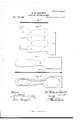
- Figure l a perspective view of the lower part, and Fig. 2 a perspective view of the upper part of the die; Fig. 3, a side view of the two when closed together; Fig. 4, the blank prepared for introduction to the die, and Fig. 5, the blank as it comes from the die; Figs. 6 to 10, diagrams illustrating previous construction.
- This invention relates to an improvement in a die to be used in the manufacture of spoons,
- A is the lower part and B the upper part of the die.
- the longitudinal shape of these shoulders corresponds to the form of the edge of the blank to be produced.
- a cavity, f is formed, which in shape corresponds to the blank to be pro quizd, and in order to hold the parts in the proper relative position vertically, a groove, g, is formed in the lower die and the upper die extended downward below the shoulder a to form a tongue, 10., to enter the said groove, and a similar groove, '03, in the upper die and similar tongue 1 on the lower die to interlock the two parts, as seen in Fig. 3, so as to prevent transverse movement or spread of the dies in consequence of the compression of the metal between the two shoulders (I. b hence the force of the die will be imparted to drawing the blank lengthwise only and not permit a thickening of the blank.
- one or both faces above the working point are recessed, as seen at n.
- the blank is cut from metal of the required thickness, and of the form seen in Fig. 4, which is substantially of the usual form but considerably shorter.
- This blank is placed on the shoulder of the lower die, and then the upper die struck 0r pressed thereon forces the metal to extend longitudinally and to produce the blank, as seen in Fig. 5, which is of substantially the usual length for the blanks for forks and spoons.
- the blank is then drawn down thinner, both ways from the narrow portion, in the usual manner and to the usual extent, and the fork or spoon cut from that blank.
- Fig. 4 is seen the usual form of blank. These are cut, as seen in Fig. 7, successively from a strip, the edge of one corresponding to the edge of the next, so that a simple shearcut, extending from edge to edge of the blank, separates one and forms the edge of the next blank.
- the bowl portion P is necessarily of a certain defined width-that is, sufficiently broad for the bowlthe remaining portion is divided between the narrower part B of the handle and the broader part S.
- These blanks are then rolled out, as seen in Fig. 8, and to produce the required longitudinal thickness, seen in Fig. 9, the metal at the thickest part being the normal thickness of the metal from which the blank is cut; hence the blank at the point B retains its original width; then from this blank the spoon-blank proper is cut, as seen in Fig. 10.
- the blank is produced, as seen in Fig. 5, of substantially the usual length, as seen in Fig. 7, with an equal thickness throughout, but greatly reduced at the narrower portion. Then, when subjected to the same drawing out as in the usual blank,
Landscapes
- Engineering & Computer Science (AREA)
- Mechanical Engineering (AREA)
- Containers Having Bodies Formed In One Piece (AREA)
Description
2 She ets-Sheet I.
H. W. BASSETT.
DIES FOR SPOON-BLANKS. No. 191,639. Patented. June 5,1877.
fly 2 N.PETB?S, PHOTO-LITNOGRAPHER. WASHINGTON D C 2 Sheets-Sheet 2'.
H. W. BASSETT. 4 DIES FOR SPOON-BLANKS. No. 191,639. Patented June 5,1877.
/fim/ 56 al/M.
%% 3] (d v/Kiwi W 62w;
N-PEfER$, PROTO-LITHOGRAPNER, WASHINGTON. D. C.
UNITED ST 'Es PATENT QFFIGE.
H. WILLIAMS BASSETT, on wALLINeFoRD, CONNECTICUT, ASSIGNOB TO HALL, ELTON & 00., on sAME PLAoE.
IMPROVEMENT IN DIES FOR SPOON-BLANKSa Specification forming part of Letters Patent No. 91,639, dated J une 5, 1877 application filed March 30, 1877.
erence marked thereon, to be a full, clear, and
exact description of the same, and which draw: ings constitute part of this specification, and represent, in-
Figure l, a perspective view of the lower part, and Fig. 2 a perspective view of the upper part of the die; Fig. 3, a side view of the two when closed together; Fig. 4, the blank prepared for introduction to the die, and Fig. 5, the blank as it comes from the die; Figs. 6 to 10, diagrams illustrating previous construction.
This invention relates to an improvement in a die to be used in the manufacture of spoons,
forks, and similar articles, the object being to avoid the scrap incident to the usual method of manufacture; and it consists of the dies in the form shown in the accompanyingdrawings, and hereinafter described.
A is the lower part and B the upper part of the die. On the lower part there is formed a shoulder, a, in thickness corresponding to the thickness of the blank, and on the upper part a corresponding shoulder, b. The longitudinal shape of these shoulders corresponds to the form of the edge of the blank to be produced. Upon the back of the lower shoulder the surface 0 rises in a vertical line, and from the shoulder 11 a similar surface, 01, extends downward, and so that when the two parts are together, as in Fig. 3, a cavity, f, is formed, which in shape corresponds to the blank to be pro duced, and in order to hold the parts in the proper relative position vertically, a groove, g, is formed in the lower die and the upper die extended downward below the shoulder a to form a tongue, 10., to enter the said groove, and a similar groove, '03, in the upper die and similar tongue 1 on the lower die to interlock the two parts, as seen in Fig. 3, so as to prevent transverse movement or spread of the dies in consequence of the compression of the metal between the two shoulders (I. b hence the force of the die will be imparted to drawing the blank lengthwise only and not permit a thickening of the blank.
To avoid friction between the vertical meeting surfaces of the die, one or both faces above the working point are recessed, as seen at n.
The blank is cut from metal of the required thickness, and of the form seen in Fig. 4, which is substantially of the usual form but considerably shorter. This blank is placed on the shoulder of the lower die, and then the upper die struck 0r pressed thereon forces the metal to extend longitudinally and to produce the blank, as seen in Fig. 5, which is of substantially the usual length for the blanks for forks and spoons. The blank is then drawn down thinner, both ways from the narrow portion, in the usual manner and to the usual extent, and the fork or spoon cut from that blank.
In Fig. 4 is seen the usual form of blank. These are cut, as seen in Fig. 7, successively from a strip, the edge of one corresponding to the edge of the next, so that a simple shearcut, extending from edge to edge of the blank, separates one and forms the edge of the next blank. As the bowl portion P is necessarily of a certain defined width-that is, sufficiently broad for the bowlthe remaining portion is divided between the narrower part B of the handle and the broader part S. These blanks are then rolled out, as seen in Fig. 8, and to produce the required longitudinal thickness, seen in Fig. 9, the metal at the thickest part being the normal thickness of the metal from which the blank is cut; hence the blank at the point B retains its original width; then from this blank the spoon-blank proper is cut, as seen in Fig. 10.
By drawing out the handle portion, as described, by these dies, the blank is produced, as seen in Fig. 5, of substantially the usual length, as seen in Fig. 7, with an equal thickness throughout, but greatly reduced at the narrower portion. Then, when subjected to the same drawing out as in the usual blank,
one part, and corresponding shoulder b and face d on the other part, and operating together, substantiaily as specified.
H. WILLIAMS BASSETT.
Witnesses GEO. M. HALLEN'BEGK, W. J. LEAVENWOBTH.
Publications (1)
| Publication Number | Publication Date |
|---|---|
| US191639A true US191639A (en) | 1877-06-05 |
Family
ID=2261046
Family Applications (1)
| Application Number | Title | Priority Date | Filing Date |
|---|---|---|---|
| US191639D Expired - Lifetime US191639A (en) | williams bassbtt |
Country Status (1)
| Country | Link |
|---|---|
| US (1) | US191639A (en) |
-
0
- US US191639D patent/US191639A/en not_active Expired - Lifetime
Similar Documents
| Publication | Publication Date | Title |
|---|---|---|
| US1680369A (en) | Method of making compound stock | |
| US774241A (en) | Dies for making keys or similar articles. | |
| US225076A (en) | Amos eidal | |
| US2210062A (en) | Method of manufacturing floor clips | |
| US460374A (en) | Manufacture of spoons and forks | |
| USRE10831E (en) | pearce | |
| US403049A (en) | Spike-blank bar | |
| US1000050A (en) | Die for forging. | |
| US192801A (en) | Improvement in blanks for table-forks | |
| US123943A (en) | Improvement in dies for making perch-irons | |
| US359961A (en) | deeble | |
| US181227A (en) | Improvement in axes | |
| US128790A (en) | Improvement in dies for the manufacture of felly-plates | |
| US351382A (en) | kiekee | |
| US1360892A (en) | Method of making spades | |
| US1935727A (en) | Method of making sliders for fasteners | |
| US1213878A (en) | Forging-die. | |
| US931471A (en) | Method of making table-knives. | |
| US416693A (en) | Herbert symonds | |
| US395888A (en) | Henry p | |
| US252676A (en) | keller | |
| US1026421A (en) | Process for the manufacture of metal forks and spoons. | |
| US325073A (en) | Peter gillick | |
| US264233A (en) | Die for upsetting gimlet bit-shanks | |
| US116345A (en) | Improvement in dies for making carriage-clips |