US191400A - Improvement in machines for whitening and shaving leather - Google Patents
Improvement in machines for whitening and shaving leather Download PDFInfo
- Publication number
- US191400A US191400A US191400DA US191400A US 191400 A US191400 A US 191400A US 191400D A US191400D A US 191400DA US 191400 A US191400 A US 191400A
- Authority
- US
- United States
- Prior art keywords
- roller
- whitening
- machines
- leather
- improvement
- Prior art date
- Legal status (The legal status is an assumption and is not a legal conclusion. Google has not performed a legal analysis and makes no representation as to the accuracy of the status listed.)
- Expired - Lifetime
Links
Images

Classifications
-
- B—PERFORMING OPERATIONS; TRANSPORTING
- B24—GRINDING; POLISHING
- B24B—MACHINES, DEVICES, OR PROCESSES FOR GRINDING OR POLISHING; DRESSING OR CONDITIONING OF ABRADING SURFACES; FEEDING OF GRINDING, POLISHING, OR LAPPING AGENTS
- B24B27/00—Other grinding machines or devices
- B24B27/02—Bench grinders
Definitions
- the design of this invention is to enable the rough loose fiber upon the inner side of the tanned skins of animals to be easily and quickly removed, so as to leave the surface smooth and not injure the leather; to which end it consists in the means employed for passing a skin in front of, and regulating its pressure upon, the abrading roller, substantially as and for the purpose hereinafter specified.
- A represents a central standard
- -B two side standards, which extend upward from a suitable base, 0, and upon their upper ends support a table, D, which has, preferably, the form shown in Fig. 1.
- an exhaust-fan, H which is provided with an induction-pipe, H, that extends forward, and at its end loosely incloses the upper and lower sides and the ends of the roller G.
- roller-shaft F and fan-shaft h are each provided with belt-pulleys f and h, re-. spectively, from which belts extend to a suitably-located driving-shaft, the arrangement being such as to cause said parts to rotate simultaneously, so that all material removed by the abrasive action of the roller Gr shall be drawn into the fan and driven from the room.
- a frame Pivoted between the lower ends of the standards B is a frame, which consists of two side bars, I, that have an L shape in side elevation, and are connected together by means of a cross-bar, I,near their upper ends, and a second cross-bar, I, that is placed at the intersection of the vertical and horizontal portions of said side bars.
- the bearings for the pivoted frame are near the longitudinal center of its horizontal portions, while its vertical portion extends upward in front of the roller-shaft F, and furnishes, at its upper end, bearings for a second roller, K, which is journaled therein parallel to, and upon a line horizontally with, the roller G.
- a set-Screw, L is fitted into a vertical threaded opening in the rear end of each horizontal arm I of the pivoted frame, and has its lower end in contact with the base-plate O, or with suitable lugs c, that are formed thereon.
- the pivoted frame may be moved outward at its upper end, within its limits of motion, but cannot pass inward beyond the limit fixed by Said screws.
- a spring, M, placed beneath the outer end of the horizontal portion of each bar I holds the pivoted frame at its inner limit, while an outward extension of the lower cross-bar I" furnishes a bearing for the foot of an operator, and enables him to move the roller K outward by a downward pressure upon said crossbar.
- the springs M may be omitted, if desired,
- a foot-lever, N (shown by dotted lines of Fig. 2,) employed for pressing the bearingroller to its inner limit.
- the device thus constructed is employed as follows: The bearing-roller is moved outward until a skin can be. passed over the same with its inner side toward the abrading-roller, after which the operators foot is removed from the foot-bar, and the springs move said bearing-roller toward said abrading-roller, and press against the latter such portion of the skin as is between their peripheries.
- the operator now moves the skin so as to bring each portion of its inner face into contact with the abrading-roller, and cause the latter to remove any loose fibers, flesh, 860., from the same.
- the surplus stock can be removed, and the skin rendered uniform in thickness.
- a fixed-bar can be employed in place of the bearing-roller, the only advantage obtained by use of the latter being a decrease-in friction, and, consequently, the more easy operation of the machines.
- a cylinder or other support for receiving the leather which is arranged parallel to, and in a plane with, the abrading-roller, and is supported within a spring-yieldingpivoted frame, and is capable of beingmoved toward or from said abrading-roller by the osoillationof said frame, substantially as and for the purpose shown.
Landscapes
- Engineering & Computer Science (AREA)
- Mechanical Engineering (AREA)
- Treatment Of Fiber Materials (AREA)
Description
2 Sheets-Sheet 1.
J'. G. BUZZELL.
MACHINE FOR WHITENING AND SHAVING LEATHER.
No. 191,400.. PatentedMay 29,1877.
. ZSheets-Sheet Z. J. G. BUZZELL.
MACHINE FO R WHITENING AND S HA'V'ING LEATHER.
No. 191,400. PatentedMay M; 1877.
UNITE JOHN .G. BUZZELL, or LYNN, MASSACHUSETTS.
IMPROVEMENT IN MACHINES FOR WHITENING AND SHAVING LEATHER Specification forming part of Letters Patent No. 191,400, dated May 29, 1877; application filed November 20, 1876.
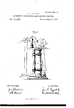
To all whom it may concern Be it known that I, JOHN G. BUZZELL, of Lynn, in the county of Essex and in the State of Massachusetts, have invented certain new and useful Improvements in Machines for Shaving and Whitening Leather; and do hereby declare that the following is a full, clear, and exact description thereof, reference being bad to the accompanying drawings, making a part of this specification, in which- Figure 1 is a perspective view of my improved machine as arranged for use, and Fig. 2 is a side elevation of the same.
Letters of like name and kind refer to like parts in each of the figures.
The design of this invention is to enable the rough loose fiber upon the inner side of the tanned skins of animals to be easily and quickly removed, so as to leave the surface smooth and not injure the leather; to which end it consists in the means employed for passing a skin in front of, and regulating its pressure upon, the abrading roller, substantially as and for the purpose hereinafter specified.
In the annexed drawings, A represents a central standard, and -B two side standards, which extend upward from a suitable base, 0, and upon their upper ends support a table, D, which has, preferably, the form shown in Fig. 1.
From the front corners of the table D two posts, E, extend upward for a short distance, and within their upper ends have journaled a shaft, E, which, between said posts or bearings, carries a roller, G, that is covered with sand-paper, emery, or other suitable abrasive material.
Upon the rear side of the table D is placed an exhaust-fan, H, which is provided with an induction-pipe, H, that extends forward, and at its end loosely incloses the upper and lower sides and the ends of the roller G.
The roller-shaft F and fan-shaft h are each provided with belt-pulleys f and h, re-. spectively, from which belts extend to a suitably-located driving-shaft, the arrangement being such as to cause said parts to rotate simultaneously, so that all material removed by the abrasive action of the roller Gr shall be drawn into the fan and driven from the room.
. Pivoted between the lower ends of the standards B is a frame, which consists of two side bars, I, that have an L shape in side elevation, and are connected together by means of a cross-bar, I,near their upper ends, and a second cross-bar, I, that is placed at the intersection of the vertical and horizontal portions of said side bars.
The bearings for the pivoted frame are near the longitudinal center of its horizontal portions, while its vertical portion extends upward in front of the roller-shaft F, and furnishes, at its upper end, bearings for a second roller, K, which is journaled therein parallel to, and upon a line horizontally with, the roller G.
As thus arranged, it will be seen that by moving the pivoted frame upon its bearings the roller K can be caused to approach to, or recede from, the roller G.
In order that the movement of the roller K toward the roller G may be regulated so as to prevent their peripheries from approaching more nearly than is desired, a set-Screw, L, is fitted into a vertical threaded opening in the rear end of each horizontal arm I of the pivoted frame, and has its lower end in contact with the base-plate O, or with suitable lugs c, that are formed thereon.
As thus arranged, by turning the screws L downward the rear ends ofthe horizontal arms I will be raised, their outer ends depressed, and the upper portion of the frame, with the roller K, moved away from the roller G, while by withdrawing said Screws said rollers will be caused to approach each other. When the screws have been adjusted, the pivoted frame may be moved outward at its upper end, within its limits of motion, but cannot pass inward beyond the limit fixed by Said screws.
A spring, M, placed beneath the outer end of the horizontal portion of each bar I holds the pivoted frame at its inner limit, while an outward extension of the lower cross-bar I" furnishes a bearing for the foot of an operator, and enables him to move the roller K outward by a downward pressure upon said crossbar.
The springs M may be omitted, if desired,
and a foot-lever, N, (shown by dotted lines of Fig. 2,) employed for pressing the bearingroller to its inner limit.
The device thus constructed is employed as follows: The bearing-roller is moved outward until a skin can be. passed over the same with its inner side toward the abrading-roller, after which the operators foot is removed from the foot-bar, and the springs move said bearing-roller toward said abrading-roller, and press against the latter such portion of the skin as is between their peripheries.
The operator now moves the skin so as to bring each portion of its inner face into contact with the abrading-roller, and cause the latter to remove any loose fibers, flesh, 860., from the same. When one portion of the skin has greater thickness than other portions the surplus stock can be removed, and the skin rendered uniform in thickness.
If desired, a fixed-bar can be employed in place of the bearing-roller, the only advantage obtained by use of the latter being a decrease-in friction, and, consequently, the more easy operation of the machines.
Having thus fully set forth the nature and merits of my inven'tiomwhat I claim as new 1s- 1. In combination with the abrading-rollor G, the bearing-roller K, the pivoted rollerframe I, If, and I, the set-screws L, and the springs M, said parts being constructed to operate in the manner and for the purpose substantially as specified.
2. In a machine for shaving and whitening leather, a cylinder or other support for receiving the leather, which is arranged parallel to, and in a plane with, the abrading-roller, and is supported within a spring-yieldingpivoted frame, and is capable of beingmoved toward or from said abrading-roller by the osoillationof said frame, substantially as and for the purpose shown. r
In testimony that I claim the foregoing I have hereunto set my hand this 14th day of November, 1876. y
, JOHN G. BUZZELL. Witnesses:
WM. HOWLAND, J OHN GARNEY.
Publications (1)
| Publication Number | Publication Date |
|---|---|
| US191400A true US191400A (en) | 1877-05-29 |
Family
ID=2260807
Family Applications (1)
| Application Number | Title | Priority Date | Filing Date |
|---|---|---|---|
| US191400D Expired - Lifetime US191400A (en) | Improvement in machines for whitening and shaving leather |
Country Status (1)
| Country | Link |
|---|---|
| US (1) | US191400A (en) |
Cited By (2)
| Publication number | Priority date | Publication date | Assignee | Title |
|---|---|---|---|---|
| US2708432A (en) * | 1949-07-06 | 1955-05-17 | Saul A Eller | Wheel truing device |
| US20050187481A1 (en) * | 2003-12-05 | 2005-08-25 | Feras Hatib | Real-time measurement of ventricular stroke volume variations by continuous arterial pulse contour analysis |
-
0
- US US191400D patent/US191400A/en not_active Expired - Lifetime
Cited By (2)
| Publication number | Priority date | Publication date | Assignee | Title |
|---|---|---|---|---|
| US2708432A (en) * | 1949-07-06 | 1955-05-17 | Saul A Eller | Wheel truing device |
| US20050187481A1 (en) * | 2003-12-05 | 2005-08-25 | Feras Hatib | Real-time measurement of ventricular stroke volume variations by continuous arterial pulse contour analysis |
Similar Documents
| Publication | Publication Date | Title |
|---|---|---|
| US270964A (en) | Machine for treating leather | |
| US320650A (en) | goettler | |
| US592992A (en) | Sandpapering-machine | |
| US953031A (en) | Grinding and polishing machine. | |
| US452004A (en) | Rotary grinding-machine | |
| US537411A (en) | Machine for concaving razors | |
| US1011306A (en) | Hide-working machine. | |
| US312643A (en) | Leather-cutting machine | |
| US132898A (en) | Improvement im machines for grinding saw-blades | |
| US1146529A (en) | Leather-buffing machine. | |
| US748391A (en) | Cutlery-polishing machine. | |
| US736278A (en) | Machine for fleshing hides. | |
| US578382A (en) | Cloth cutting machine | |
| US367200A (en) | Isidoe deesdneb | |
| US477459A (en) | Leather-skiving machine | |
| US454480A (en) | B u r nis hin g - m a c hin e | |
| US202226A (en) | Improvement in machines for shaving and whitening | |
| US941957A (en) | Sanding, abrading, or polishing machine. | |
| US426397A (en) | And william h | |
| US477458A (en) | Leather-skiving machine | |
| US137104A (en) | Improvement in machines for grinding metal castings | |
| US998191A (en) | Hat-tip-clipping machine. | |
| US575350A (en) | B u r nis hin g - m a c hin e | |
| US178398A (en) | Improvement in sandpapering-machines | |
| US165073A (en) | Improvement |