US190898A - Improvement in quadruplex telegraphs - Google Patents
Improvement in quadruplex telegraphs Download PDFInfo
- Publication number
- US190898A US190898A US190898DA US190898A US 190898 A US190898 A US 190898A US 190898D A US190898D A US 190898DA US 190898 A US190898 A US 190898A
- Authority
- US
- United States
- Prior art keywords
- instrument
- wire
- receiving
- bridge
- current
- Prior art date
- Legal status (The legal status is an assumption and is not a legal conclusion. Google has not performed a legal analysis and makes no representation as to the accuracy of the status listed.)
- Expired - Lifetime
Links
- 230000001264 neutralization Effects 0.000 description 6
- 230000000694 effects Effects 0.000 description 4
- 238000010276 construction Methods 0.000 description 2
- 238000007599 discharging Methods 0.000 description 2
- 230000002441 reversible Effects 0.000 description 2
Images

Classifications
-
- H—ELECTRICITY
- H04—ELECTRIC COMMUNICATION TECHNIQUE
- H04N—PICTORIAL COMMUNICATION, e.g. TELEVISION
- H04N7/00—Television systems
- H04N7/16—Analogue secrecy systems; Analogue subscription systems
- H04N7/173—Analogue secrecy systems; Analogue subscription systems with two-way working, e.g. subscriber sending a programme selection signal
- H04N7/17309—Transmission or handling of upstream communications
- H04N7/17318—Direct or substantially direct transmission and handling of requests
Definitions
- My invention relates to that class of quadruplex telegraphs in which two receiving-instruments are employed at each terminal station, one being operated by changes in the polarity of the line-current without reference to its strength, and the other by changes in the strength of the current without reference to its polarity.
- My improvement consists in the peculiar construction and arrangement of a differential receiving-instrument, operated by changes in the strength of the current, in combination with a condenser, which is charged and discharged by the current traversing the bridgewire, by means of which combination the mutilation of the signals upon this instrument, resulting from the reversal of the polarity of the line-current, which has hitherto formed a serious obstacle in working longlines, is more effectually prevented.
- P represents a polarized relay or receiving instrument, which is operated solely by changes in the polarity of the current, and It represents a neutral relay, which is operated solely by changes in the strength of the current. In some instances this relay is also provided with a polarized armature.
- the main magnet of the receiving-instrument B is provided with two equal and opposing helices, m 'n, preferably arranged in the manner shown in the drawing, although the precise arrangement is not very material.
- the rheostats or resistances A and B, which form the first and second sides of the bridge, are preferably made equal to each other, and this being the case the resistance X should, of course, be made equal to the resistance of the line.
- the receiving instrument R is provided with an auxiliary magnet, T, which acts upon the same armature-lever with the main magnet m n.
- This auxiliary magnet is inserted in a wire. 7, which is connected to the bridgewire 3 5, and through which the condenserO is charged and discharged.
- the charging and discharging of the condenser is effected as usual, by means of a rheostat, D, placed in the bridge-wire between the point of junction of the Wire 7 and that of the Wire 8, which is attached to the opposite pole of the condenser.
- the outgoing currents pass over the wire 1 to the point 2, where they divide into two equal portions, one portion going to line by way of A, 3, m, and 4, and the other to earth by way of B, 5, n, X, and 6.
- the bridge-wire 3 being neutral in respect to outgoing currents, the instrument P will not be affected, nor will the instrument R, for the reason that the currents traversing the opposing helices m n are necessarily equal to each other.
- a receiving-instrument composed of a difl'erential magnet whose opposing coils are respectively included in the circuit of the main and of the artificial line, in combination with an auxiliary magnet, so arranged as to be operated by the charge or discharge of a condenser.
- a receiving-instrument provided with two electro-magnets acting upon the same armature-lever, one a differential magnet, whose opposing coils are respectively included in the circuit of the main and of the artificial line, and the other so arranged as to be actuated by the charge or discharge of a condenser, in combination with a rheostat inserted in the bridge-wire, to effect the charging of said condenser, substantially as and for the purpose herein specified.
Description
G. B. PRESCOTT.
QUADRUPLEX TELEGRAPH.
No. 190,898. Patented May15, 1877.
lllllhiiiiii KEYS AN D BA TTERY.
INVENTOR.
WITNESSES "THERE. PNOTO-LITHOGHAPNER. WASHINGTON, D c.
" NITED STATEs PATENT OFFICE.
GEORGE B. PRESCOTT, OF NEW YORK, N. Y.
IMPROVEMENT IN QUADRUPLEX TELEGRAPHS.
Specification forming part of Letters Patent No. 190,898, dated May 15, 1877 application filed April 22, 1876.
To all whom it may concern Be it known that I, GEORGE B. PRESCOTT, of the city of New York, in the county and State of New York, have invented certain new and useful Improvements in Quadruplex Telegraphs; and I do hereby declare 'that the following is a full, clear, and exact description thereof, which will enable others skilled in the art to which it appertains to make and use the same, reference being had to the accompanying drawings, and to the letters of reference marked thereon, which form a part of this specification.
My invention relates to that class of quadruplex telegraphs in which two receiving-instruments are employed at each terminal station, one being operated by changes in the polarity of the line-current without reference to its strength, and the other by changes in the strength of the current without reference to its polarity.
My improvement consists in the peculiar construction and arrangement of a differential receiving-instrument, operated by changes in the strength of the current, in combination with a condenser, which is charged and discharged by the current traversing the bridgewire, by means of which combination the mutilation of the signals upon this instrument, resulting from the reversal of the polarity of the line-current, which has hitherto formed a serious obstacle in working longlines, is more effectually prevented.
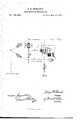
In the accompanying drawing, P represents a polarized relay or receiving instrument, which is operated solely by changes in the polarity of the current, and It represents a neutral relay, which is operated solely by changes in the strength of the current. In some instances this relay is also provided with a polarized armature. The main magnet of the receiving-instrument B is provided with two equal and opposing helices, m 'n, preferably arranged in the manner shown in the drawing, although the precise arrangement is not very material. The rheostats or resistances A and B, which form the first and second sides of the bridge, are preferably made equal to each other, and this being the case the resistance X should, of course, be made equal to the resistance of the line. When the respective resistances are thus arranged the bridge-wire 3 5, polarized receiving-instrument P, and condenser G will be in a neutral position in respect to outgoing currents.
The receiving instrument R is provided with an auxiliary magnet, T, which acts upon the same armature-lever with the main magnet m n. This auxiliary magnet is inserted in a wire. 7, which is connected to the bridgewire 3 5, and through which the condenserO is charged and discharged. The charging and discharging of the condenser is effected as usual, by means of a rheostat, D, placed in the bridge-wire between the point of junction of the Wire 7 and that of the Wire 8, which is attached to the opposite pole of the condenser.
The outgoing currents, without regard to their strength or polarity, pass over the wire 1 to the point 2, where they divide into two equal portions, one portion going to line by way of A, 3, m, and 4, and the other to earth by way of B, 5, n, X, and 6. The bridge-wire 3 5, being neutral in respect to outgoing currents, the instrument P will not be affected, nor will the instrument R, for the reason that the currents traversing the opposing helices m n are necessarily equal to each other.
For the purposes of this explanation it is only necessary to take into consideration the effects of such incoming currents as are of sufficient strength to actuate the receiving instrument R. In my arrangement the full strength of the incoming current, whatever may be its polarity, passes, unopposed, through the helix m of the instrument R, and thence to the point 3, where it divides, one portion going to earth by way of A, 2, and 1, another portion by way of 5, B, 2, and 1, and the remainder by way of 5 through the other coil 12 of the receiving-instrument R, (its direction now being such as to assist the action of the other helix m,) and thence through the rheostat X to the earth. The incoming current traversing the bridge-wire from 3 to 5, being partially obstructed by the rheostat D, a portion of it flows through the wire 7 and charges the condenser G.
If, now, the polarity of the current upon the line be suddenly reversed for the purpose of operating the polarized receiving-instrument P, the armature of the instrument It tends to fall off momentarily while the change of polarity is taking place, but this action is prevented by the discharge of the condenser G through the wire 7, which occurs at the same instant, and, acting upon the auxiliary magnet r, retains the armature-lever a in its place.
I am aware that it is not new to place a receiving-instrument, operated by changes in the strength of current in the bridge-wire, in combination with an auxiliary magnet, a condenser, and a rheostat; nor is it new to make use of a differential magnet placed in the circuit of the main and artificial line, instead of in the bridge-wire, in combination with another receiving-instrument placed in the bridge-wire. I believe it, however, to be both new and important to substitute a differential receiving-instrument in the circuit of both the main and artificial lines for the receiving-instrument heretofore placed in the bridge-wire, and to combine therewith an auxiliary magnet actuated by the charge or discharge of a condenser connected to the bridge-wire, as I am thereby enabled to util ize the entire strength of the incoming current, and obtain at least double the effective working margin from a given strength of current passing over the line, without sacrificing any of the advantages heretofore derived from placing this portion of the apparatus in the bridge-wire. By the use of my improvement it, therefore, becomes possible to work the quadruplex apparatus over lines of greater length than has hitherto been the case.
I claim as my invention- 1. A receiving-instrument composed of a difl'erential magnet whose opposing coils are respectively included in the circuit of the main and of the artificial line, in combination with an auxiliary magnet, so arranged as to be operated by the charge or discharge of a condenser.
2. A receiving-instrument provided with two electro-magnets acting upon the same armature-lever, one a differential magnet, whose opposing coils are respectively included in the circuit of the main and of the artificial line, and the other so arranged as to be actuated by the charge or discharge of a condenser, in combination with a rheostat inserted in the bridge-wire, to effect the charging of said condenser, substantially as and for the purpose herein specified.
In testimony that I claim the foregoing I have hereunto affixed my signature in the presence of two witnesses.
GEORGE BARTLETT PRESCOTT.
Witnesses:
H. M. HAIGH, E. W. GRIFFITH.
Publications (1)
| Publication Number | Publication Date |
|---|---|
| US190898A true US190898A (en) | 1877-05-15 |
Family
ID=2260305
Family Applications (1)
| Application Number | Title | Priority Date | Filing Date |
|---|---|---|---|
| US190898D Expired - Lifetime US190898A (en) | Improvement in quadruplex telegraphs |
Country Status (1)
| Country | Link |
|---|---|
| US (1) | US190898A (en) |
-
0
- US US190898D patent/US190898A/en not_active Expired - Lifetime
Similar Documents
| Publication | Publication Date | Title |
|---|---|---|
| US190898A (en) | Improvement in quadruplex telegraphs | |
| US349945A (en) | William mavee | |
| US201374A (en) | Improvement in apparatus for neutralizing the effects of induced electrical currents | |
| US475938A (en) | Telegraphy | |
| US781752A (en) | Telegraph. | |
| US358890A (en) | Beeghe | |
| US196248A (en) | Improvement in quadruplex telegraphs | |
| US126847A (en) | Improvement in duplex telegraph apparatus | |
| US236321A (en) | Joseph e | |
| US909877A (en) | Telegraphy. | |
| US238094A (en) | Geoeges dtofeeville | |
| US191439A (en) | Improvement in quadruplex telegraphs | |
| US154479A (en) | Improvement in duplex telegraphs | |
| US259106A (en) | Duplex telegraph | |
| US217781A (en) | Improvement in sextuplex telegraphs | |
| US711943A (en) | Telegraphy. | |
| US1333014A (en) | Signaling system | |
| US684415A (en) | Quadruplex telegraphy. | |
| US1254829A (en) | Means for compensating for disturbances of earth potential. | |
| US165263A (en) | Improvement in duplex telegraphs | |
| US166305A (en) | Improvement in telegraphic circuits | |
| US182486A (en) | Improvement in electrical circuits for chemical telegraphs | |
| US258366A (en) | Charles l | |
| US332549A (en) | nicholson | |
| USRE8889E (en) | Improvement in |