US1908960A - Method of and apparatus for feeding or pulling tape - Google Patents
Method of and apparatus for feeding or pulling tape Download PDFInfo
- Publication number
- US1908960A US1908960A US441963A US44196330A US1908960A US 1908960 A US1908960 A US 1908960A US 441963 A US441963 A US 441963A US 44196330 A US44196330 A US 44196330A US 1908960 A US1908960 A US 1908960A
- Authority
- US
- United States
- Prior art keywords
- tape
- loop
- ticker
- projection
- projection field
- Prior art date
- Legal status (The legal status is an assumption and is not a legal conclusion. Google has not performed a legal analysis and makes no representation as to the accuracy of the status listed.)
- Expired - Lifetime
Links
Images

Classifications
-
- H—ELECTRICITY
- H04—ELECTRIC COMMUNICATION TECHNIQUE
- H04L—TRANSMISSION OF DIGITAL INFORMATION, e.g. TELEGRAPHIC COMMUNICATION
- H04L13/00—Details of the apparatus or circuits covered by groups H04L15/00 or H04L17/00
- H04L13/02—Details not particular to receiver or transmitter
- H04L13/06—Tape or page guiding or feeding devices
Definitions
- My invention relates to a tape-pulling system and involves a method of and apparatus for pulling tape along a path which extends, for example, through a projection field.
- My invention involves a tape-pulling system controlled by or responsiveto the control effected'by the tape upon suitable mechanism.
- My invention also relates to air-pressure control mechanism actuated in a novel manner by the tape after passage thereof from suitable printing mechanism. 7
- My invention resides in the method, apparatus, system, features of construction, and combinations of parts of the character hereinafter described and claimed.
- Figure 1 is a plan view, partly broken away, and diagrammatically showing one form of a tape-pulling system as constructed in accordance with my invention
- Figure 1a is a vertical sectional view, partly in elevation, and is taken on the line 1w1a of Fig. 1 looking in the direction of the arrows;
- Fig. 2 is an enlarged vertical sectional view, partly in elevation, of a part of the control mechanism of Fig. 1;
- Fig. 3 is an enlarged fragmentary view, partly in horizontal section, mechanism shown in Fig. 1
- Figs. 4, and 6 are vertical sectional views taken, respectively, on the lines 4-4, 55 and 6-6 of Fig. 3;
- Fig. 7 is a plan view showing another form of a tape-pulling system as constructed in accordance with my invention.
- Fig. 8 is a transverse, vertical sectional view, partly in elevation, of a part of the mechanism shown in Fig. 7
- A represents of a part of the l mounted in the gear hOlISlIlg 5 and, by said mo. Serial No. 441,963.
- ticker or typewriting mechanisms of the character stated print characters indicative of stock quotations on a tape T, the printed tape, in a pulsating manner, passing from the printing mechanism A in the direction of the arrows a, Figs. 1 and 3.
- ticker mechanism shall be understood as generically comprehending or including typewriter mechanism, stock ticker mechanisms, as aforesaid, and the like.
- rollers. 1 and 2 are shown as coacting with said tape T.
- the roller 1 is of the idler type and it may be rotatably mounted at one end of an arm 3 pivoted at 4 on a suitable support which, as hereinafter described, may be a gear housing 5.
- a spring 6 which may be mounted on said gear housing 5 and coacts with the arm 3 to bias the same in a clockwise direction, Figfl.
- the roller 2 may be rotated in any suitable manner and by any suitable mechanism.
- a motor M is utilized for this purpose, the motor armature rotating a worm gear 7 which meshes with and drives a gear 8 to which is connected a shaft. carrying the aforesaid roller 2.
- the gears 7 and 8 are gears, the rotative speed of the tape-pulling roller 2 is suitably reduced compared to the rotative speed of the armature of motor M.
- the aforesaid projection field or zone is constituted by anaperture 9, Fig. 111, at the front of a condenser housing 10 into which light passes'from a suitable source of light disposed within a lamp housing 11.
- the projecting beam of light traverses that section of the tape T framed by the aperture 9 and then passes into coacting relation with a mirror 12" from which said light beam passes to and throu h an objective or projection lens 13 where y images of the tape'characters are obtained on any suitable screen, not shown.
- tape having stock quotation characters printed thereon issues from the ticker mechanism in a pulsating manner and more particularly in an irregular pulsating manner at times.
- the latter should pass through the projection field or zone in a regular or even manner even though, at times, there may be a temporary cessation of tape movement through said field or zone, the latter arising, ordinarily, because of temporary discontinuation of the ticker mechanism.
- a housing H forming an air chamber 15 from which air is drawn in any suitable manner such, for example, as through a conduit 16 opening into the inlet side ofa housing 17 containing suitable fan structure, not shown, the latter being operated by a motor 18, or the like, whereby air is drawn through the conduit 16 in the direction of the arrow 6, Fig. 1.
- the housing H has a wall 19, the exterior surface of which the tape T, to more or less extent, is adapted to engage as it passes toward the aforesaid, projection field.
- the wall 19 has a .perforation or slot 20 through which, by the motor 18, air may be drawn into the chamber '15 from the atmosphere provided that said slot 20 is-not closed or substantially closed by an adjacent section of the tape T.
- the contact members 22 and 23 may be carried, in suitable insulated relation, by a lateral arm 24a of a member 24, Fig. 2.
- one of them may carry an insu lating member 25 connected by a member 26 with a plunger or piston- 27 slidably dis osed, in'suitable sealed relation, in a cylin er or housing 28.
- Extending between the cylinder 28 and the aforesaid housing H is a member 29 having a passage 30 placing said cylinder and housing in communicating relation.
- the housing H, member-24, cylinder 28 and member 29 may be intergrally formed with each other, as by a casting process, and the structure thus produced may be secured to the side of the condenser housing 10 as shown in Figs. 1 and Y 3; however, if desired, said structure may be disposed or mounted in any other suitable manner.
- the tape section with which the projecting light beam coacts at any given time extends horizontally and is disposed edgewise, i. e., perpendicular to the plane of the sheet on which the drawing is made. Said tape section is maintained in this position by the rollers 1 and 2 in conof they tape T in engagement with the nose 34 of the housing H under pressure conditions suflicient to insure the requisite tautness of the tape section extending to the rollers 1 and 2 but insufiicient to impede movement of the tape, under the influence of said rollers, to an undesired or unwarranted extent.
- the longitudinal axis of the tape path through the projection field is disposed at right angles to the path taken by the tape as it leaves the ticker mechanism. This is desirable but not necessary and may be varied, if desired,
- Figs. 1,2 and 3 flatwise and in a horizontal Y direction. Due to the fact that an advanced tape section is held, by the lever end 31a, in vertical edgewise position, it results that the tape T, after leaving the printing wheel Assumlng that a tape loop such as shown by the full lines of Fig. 3 has been formed I between the ticker mechanism and the lever end 31a, it will be obvious that the tape section immediately adjacent the wall 19 of housing H will have come nearly to vertical edgewise position and that this relation to greater and greater extent obtains as the lever end 31a is approached.
- the configuration of the exterior surface of wall 19 is shaped substantially the same as the configuration of the aforesaid last named tape section.
- the slot 20 remains covered and the motor M remains in operation.
- the more rapid operation of the ta -pulling roller 2 causes reduction in size 0 the tape loop between the ticker mechanism A and lever end 31a and, if this reduction in size continues to a suflicient extent, the slot 20 will be uncovered to permit passage of air therethrough from the atmosphere in the-manner described above.
- pressure conditions on the pis- .ton 27 are equalized and the latter moves downwardly whereby the circuit through the motor M is opened.
- the arrangement may be such that said circuit is opened and closed in quick succession or, alternatively, the resistance characteristics the motor speed.
- Figs. 7 and 8 there is shown another form of my invention for controlling of the motor circuit to effect change in movement of a tape through a suitable pro- I jection field.
- the tape T passes from the ticker mechanism, not shown, in the direction of the arrows a, Figs. 7 and 8, flatwise and in a horizontal direction. It is then so controlled that it passes through the projection field flatwise and in a horizontal direction.
- the tape is in inverted position (upside-down) as regaids the manner in WlllCh it comes from the ticker mechanism and, therefore, it'results that the tape, between the ticker mechanism and the projection field,has a 180 degree twist therein.
- the tape-pulling mechanism is the same as heretofore described in connection with Fig. 1, the longitudinal axes of the rollers 1 and 2 being horizoutally disposed whereas in Fig. 1, such axes are vertically disposed.
- the projection field or projection aperture is indicated at 40, Fig. 7, the projectlon light beam, as heretofore described but not necessarily, passing through said aperture and the tape sectiohdefined thereby, said light beam thereafter coacting with the projection lens 13.
- the aforesaid pulling rollers 1 and 2 are disposed adjacent the exit end of theaperture 40, a member 41 coactablewith the tape being positioned adjacent the entrance of said aperture.
- the lower end of the member 41 corresponds in function with the. hereinbe fore described lever end 31a.
- said member 41 may be a gravity-controlled weight, a downwardly-biased spring or the like; it coacts with a fixed surface at that side of the tape removed therefrom and, in conjunction with the rollers 1 and 2, causes the tape section in the projection field to have the necessary degree of tautne'ss for projection purposes.
- the longitudinal axis of the projection field 40 is disposed preferably, but not necessarily at right angles to the path taken by the tape as it leaves the ticker mechanism, such path being designated by the-arrow a, Fig. 7
- the tape passes from the ticker mechanism horizontal, flatwise and with that surface uppermost to which the ink has been applied for forming the printed characters.
- the member 41, or equivalentfthe inked tape surface is maintainedhorizontal, flatwise and facing downwardly as the tape enters and passes through the projection field.
- the aforesaid 180 degree tape twist exists between the projection field and the ticker mechanism.
- a tape loop is formed after the tape leaves the ticker mechanism, and the configuration or depth of such tape loop is utilizable, in accordance with my invention, for controling movement of the tape through the projection field.
- vacuum-producing mechanism of the general character hereinbefore described with the exception that ahousing H1 is substituted for the housing H of Figs. 1, 2 and 3.
- the housing H1 comprises or has a wall 42, the exterior surface of which the tape T, to more or less extent, is adapted to engage as it passes toward the projection field 40.
- the Wall 42 has a slot or passage 43 through which, at times, air passes to the chamber 15 of housing H1, the latter having an evacuating conduit 16 connected thereto the same as described in connectionwith the housing H.
- the switch mechanism of Fig. 8 controls the motor M of Fig. 7 the same as described in connection with Figs. 1, 2 and 3..
- the control which may be exercised by any given tape section on the motor M occurs before that section, to any substantial extent, has passed into tape loop formation.
- the aforesaid wall 42 of housing H1 be disposed substantially transversely and beneath the path taken by the tape after leaving the ticker mechanism.
- Said wall 42 should be curved somewhat as shown in Fig. 8 and the exterior surface thereof should be slightly tilted, with respect to the plane of the paper on which the drawing is made, in a progressive manner for increasing distances from the ticker mechanism.
- housing H1 if housing H1 is to be ositioned as' shown, then the configuration o the exterior surface of housing wall 42 should be such that the adjacent section of the tape T, as positioned in Fig. 8, is entirely flush thereagainst, and that said tape section has closed the slot 43. It shall be understood, however, that the housing H1 may be positioned otherwise as desired and that the housing wall 43- a twisted tape loop at or adjacent the entrance to the projection field coacts with a surface having an air passage therethrough to produce variation in the tape movement through the projection field. threaded through the projection field before operation of the projection system, the twisted tape loop is formed, and successive sections of the tape pass progressively through the twisted loop formation.
- my invention is not to be limited to lamp housings condenser housings, reflecting systems, etc. o any particular type since myinvention is ap plicable to any suitable type of such arrangements.
- the method which comprises supporting said tape for movement through a projection field with said one surface facing in a direction different than said predetermined direction,
- a-twisted tape loop is disposed adjacent the entrance to said pro-' jection field, and controlling movement of said tape through said projection field in response to change in configuration of said tape loop.
- a character-bearlng tape passes from ticker mechanism flatwise and'with one surface facing in a predetermined direction, comprises supporting said tape-for movement through a projectionfieldwith said one surface facing in a direction different than said the method. which predetermined direction, forming a loop between said'ticker mechanism and the projection field whereby a twisted tape loop is disposed adjacent the entrance to said projection field, and efl'ecting movement of said tape through said projection field response to increase in depth of said tape loop.
- ticker mechanism from which a character-bearing tape passes flatwise and with one surface facing in predemined direction, means for supporting the tape in a projection field with said one surface facin in a direction different than said one irection, means for pulling the tape through said projection field, there being a twisted tape loop between said projection field and said ticker mechanism which changes in configuration when said tape-pulling means operates non-synchronously with respect to said ticker mechanism, the twist in said tape loop being formed due to the different facing relations of sections of said tape, and means for varying the operation of said tape-pulling means in response to change in configuration of said tape loop.
- ticker mechanism means for supporting the tape ejected therefrom in a projection field, said ticker mechanism and said means being so positioned as to form a twist in the ta e therebetween and with a loop at the twiste ta section, means for ulling said tape throug said projection.
- ticker mechanism means for supporting the tape ejected therefromin a projection field, said ticker mechanism and said means being so positioned as to form a twist in the tape loop therebctween and with a loop at the twisted tape section, means for pulling said tape through said projection field, and means comprising an air chamber for controlling operation of said tape-pulling means, the twisted tape loop controlling the pressure in said air chamber.
- ticker mechanism from which character-bearing tape passes along a path, means for supporting the tape in a projection field disposed substantially at right angles with respect to said path, said ticker mechanism and said means being so positioned as to form a twist in the tape loop therebetween and with a loop at the twisted tape section, means for pulling said tape through said projection field, and means comprising an air chamber for controlling operation of said tape-pulling means, a-wall of said chamber having a passage for placing the latter in communication with the atmosphere, the twisted tape loop opening and closing said passage to control the pressure in said air chamber.
- a character-bearing tape passes from ticker mechanism flatwise and with one surface facing in a predetermined direction
- the method which comprises supporting said tape for movement through a projection field with said one surface maintained in vertical edgewise relation, forming a loop between said ticker mechanism and the projection field whereby a twisted tape loop is disposed adjacent the entrance to said pro ection field, and controlling movement of said tape through said projection field in response to change in configuration of said tape loop.
- a character-bearing tape passes from ticker mechanism flatwise and with one surface facing upwardly
- the method which comprises supporting said tape for movement through a projectionfield with said one surface facing downwardly, forming a loop between said ticker mechanism and the projection field whereby a twisted tape loop is disposed adjacent the entrance to said pro'ection field, and controlling movement 0 said tape through said rojection field in response to change in con guration of said tape loop.
- a character-bearing tape passes flatwise from ticker mechanism and with one surface facing upwardly
- the method which comprises supporting said tape for horizontal movement throu h a projection field with said one surface acing downwardl and controlling movement of said tape t rough said projection field in response to change in configuration of a tape loop disposed at the entrance to said projection field.
- ticker mechanism from which a character-bearing tape passes flattwisted tape loop between said projection field and said ticker mechanism which changes in configuration when said tape-pulling means operates non-synchronously with respect to said ticker mechanism, the twist in said tape loop being. formed due to the different facing relations of sections of said tape, and means for varying the operation of said tape-pulling means in response to change in configuration of said tape loop.
- ticker mechanism from which a character-bearing tape passes flatwise and with one surface facing upwardly, means for supporting the tape in a projection field with said one surface facing downwardly, means for pulling the tape through said projection field, there being a twisted tape loop between said projection fieldand said ticker mechanism which changes inconfiguration when said tape-pulling means operates non-synchronously with respect to said ticker mechanism, the twist in said ta e loop being formed due to the different acing relations of sections of said tape, and means for varying the operation of said tape-pulling means in response to change in configuration of said tape loop.
- ticker mechanism from which a character-bearing tape passes fiatwise and with one surface facing in predetermined direction, means for supporting the tape in a projection field with said one surface facing in a direction different than said one direction, means for pulling the tape through said projection field, there being a twisted tape loop between said projection field and said ticker mechanism which changes in configuration when said tape-pulling means operates non-synchronously with respect to said ticker mechanism, the twist in said tape loop being formed due to the difierent facing relations of sections of said tape, and means for varying the operation of said taipe-pulling means in response to change in con guration of said tape loop, said last named means comprising a suction housing having a surface conformable in configuration with that of the adjacent section of the tape loop.
- ticker mechanism from which a character-bearing tape passes flatwiseand with one surface facing in predetermined direction, means for supporting the tape for horizontal movement hrough a projection field while maintaine in vertical edgewise relation, means for pulling the tape through said projection field, there being a twisted tape loop between said projection field and said ticker mechanism which changes in configuration when said tape-pullof a tape loop at the entrance to said projection field, said mechanism comprising a housing having a suction port adapted to be more or less covered by an adjacent section of the tape loop, means for withdrawing air from said housmg, a cylinder, a conduit connecting said housing and cylinder, and a piston movable in said cylinder in response to change in coverage of said suction port by the adjacent tape section, said piston controlling the circuit of said motor.
- a motor for pulling a character-bearing tape through a projection field
- suction-control mechanism for varying the operation of said motor in accordance with change in configuration of a tape loop at the entrance to said projection field
- said mechanism comprising a housing having a suction port adapted to be more or less covered by an adjacent section of the tape loop, means for withdrawing air from said housing, a cylinder, a conduit connecting said housing and cylinder, and a piston movable in said cylinder in response to 1 0 change in coverage of said suction port by the adjacent tape section, said piston carrying an electrical contact member for opening and closing the circuit of said motor.
Landscapes
- Engineering & Computer Science (AREA)
- Computer Networks & Wireless Communication (AREA)
- Signal Processing (AREA)
- Advancing Webs (AREA)
Description
May 16, 1933.
K. L. CURTIS METHGD OF AND' APPARATUS FOR FEEDING 0R PULLING TAPE Filed April 5, 1950 2 Sheets-Sheet l 8 6 Z J 'h M ,4 [M35 w 9 s Rm 0. ms w mw n H. w a Z w 87 Z a W M 9- M :ATTORNEYS "May16,1933.- v m. um l 1,908,960
OF AND APPARATUS FOR FEEDING 6R PULLING TAPE Filed April 5, 1950 2 Sheets-Sheet 2 INVENTOR- ATTORNEYS KENNETH L. CURTIS, OF NEW YORK, IN. PICTURE SCREEN CORPORATION, 01 NEW YORK, N. Y A CORPORATION OF DELA- Patented May 16, 1933 WARE Y; ABSIGNOB TO TBANS-LUX DAY'LIGET METHOD OEANlD APPARATUS FOR- FEEDING OR PULLING TAIPE Application filed April 5,
My invention relates to a tape-pulling system and involves a method of and apparatus for pulling tape along a path which extends, for example, through a projection field.
My invention, among other prominent features, involves a tape-pulling system controlled by or responsiveto the control effected'by the tape upon suitable mechanism.
My invention also relates to air-pressure control mechanism actuated in a novel manner by the tape after passage thereof from suitable printing mechanism. 7
Various other objects, advantages and characteristics of my invention will become apparent from the following description tak- -en in connection with the accompanying drawings. 7
My invention resides in the method, apparatus, system, features of construction, and combinations of parts of the character hereinafter described and claimed.
For an understanding of my method and for anillustration of some of the many forms of my apparatus, reference is to be had to the accompanying drawings, in which;
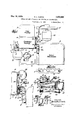
Figure 1 is a plan view, partly broken away, and diagrammatically showing one form of a tape-pulling system as constructed in accordance with my invention;
Figure 1a is a vertical sectional view, partly in elevation, and is taken on the line 1w1a of Fig. 1 looking in the direction of the arrows;
Fig. 2 is an enlarged vertical sectional view, partly in elevation, of a part of the control mechanism of Fig. 1;
Fig. 3 is an enlarged fragmentary view, partly in horizontal section, mechanism shown in Fig. 1
Figs. 4, and 6 are vertical sectional views taken, respectively, on the lines 4-4, 55 and 6-6 of Fig. 3;
Fig. 7 is a plan view showing another form of a tape-pulling system as constructed in accordance with my invention; and
Fig. 8 is a transverse, vertical sectional view, partly in elevation, of a part of the mechanism shown in Fig. 7
' Referring to Figs. 1 and 3, A represents of a part of the l mounted in the gear hOlISlIlg 5 and, by said mo. Serial No. 441,963.
suitable printing mechanism such, for example, as typewriter mechanism having individual keys, stock ticker mechanism of a character well known to the art and more particularly such as the high speed ticker mechanism now coming into use, such stock ticker mechanisms having rotatable printing wheels. As is well understood, ticker or typewriting mechanisms of the character stated print characters indicative of stock quotations on a tape T, the printed tape, in a pulsating manner, passing from the printing mechanism A in the direction of the arrows a, Figs. 1 and 3. In the appended claims, the term ticker mechanism shall be understood as generically comprehending or including typewriter mechanism, stock ticker mechanisms, as aforesaid, and the like.
To the end that the tape T may be pulled or moved through a pro ection field or zone where a projecting light beam coacts therewith, rollers. 1 and 2 are shown as coacting with said tape T. As herein illustrated, the roller 1 is of the idler type and it may be rotatably mounted at one end of an arm 3 pivoted at 4 on a suitable support which, as hereinafter described, may be a gear housing 5. For biasing the roller 1 toward the roller 2, there may be utilized a spring 6 which may be mounted on said gear housing 5 and coacts with the arm 3 to bias the same in a clockwise direction, Figfl.
The roller 2 may be rotated in any suitable manner and by any suitable mechanism. As herein shown, a motor M is utilized for this purpose, the motor armature rotating a worm gear 7 which meshes with and drives a gear 8 to which is connected a shaft. carrying the aforesaid roller 2. 'The gears 7 and 8 are gears, the rotative speed of the tape-pulling roller 2 is suitably reduced compared to the rotative speed of the armature of motor M.
As herein illustrated although not necessarily, the aforesaid projection field or zone is constituted by anaperture 9, Fig. 111, at the front of a condenser housing 10 into which light passes'from a suitable source of light disposed within a lamp housing 11. As may be determined from Figs. 1 and 1a, the projecting beam of light traverses that section of the tape T framed by the aperture 9 and then passes into coacting relation with a mirror 12" from which said light beam passes to and throu h an objective or projection lens 13 where y images of the tape'characters are obtained on any suitable screen, not shown. It is well understood in the art that tape having stock quotation characters printed thereon issues from the ticker mechanism in a pulsating manner and more particularly in an irregular pulsating manner at times. In contradistinction to this pulsating movement of the tape, the latter should pass through the projection field or zone in a regular or even manner even though, at times, there may be a temporary cessation of tape movement through said field or zone, the latter arising, ordinarily, because of temporary discontinuation of the ticker mechanism.
In accordance with my invention, operation of the tape-pulling mechanism, herein shown as the motor M, is controlled in a novel manner by the tape T soon after the latter leaves the ticker mechanism A. To this end and as shown in Figs. 1-6 which illustrate a preferred arrangem nt, there may be utilized a housing H forming an air chamber 15 from which air is drawn in any suitable manner such, for example, as through a conduit 16 opening into the inlet side ofa housing 17 containing suitable fan structure, not shown, the latter being operated by a motor 18, or the like, whereby air is drawn through the conduit 16 in the direction of the arrow 6, Fig. 1.
The housing H has a wall 19, the exterior surface of which the tape T, to more or less extent, is adapted to engage as it passes toward the aforesaid, projection field. The wall 19 has a .perforation or slot 20 through which, by the motor 18, air may be drawn into the chamber '15 from the atmosphere provided that said slot 20 is-not closed or substantially closed by an adjacent section of the tape T.
In accordance with my invention, operation ofthe tape-pulling motor M continues so longas air, to any substantial extent, is preanism. The contact members 22 and 23 may be carried, in suitable insulated relation, by a lateral arm 24a of a member 24, Fig. 2.
For maintaining the contact members 22 and 23 closed as shown in Fig. 2 or for holding said contact members open, one of them, as the contact member 23, may carry an insu lating member 25 connected by a member 26 with a plunger or piston- 27 slidably dis osed, in'suitable sealed relation, in a cylin er or housing 28. Extending between the cylinder 28 and the aforesaid housing H is a member 29 having a passage 30 placing said cylinder and housing in communicating relation.
9 Preferably but not necessarily, the housing H, member-24, cylinder 28 and member 29 may be intergrally formed with each other, as by a casting process, and the structure thus produced may be secured to the side of the condenser housing 10 as shown in Figs. 1 and Y 3; however, if desired, said structure may be disposed or mounted in any other suitable manner.
When the air pressure conditions on both sides of'the piston 27 are substantially balanced, the latter remains in a position lower than the one shown in Fig. 2 and sufliciently lower to cause the contactsof contact members 22 and 23 to be separated, the contact member 23 supporting piston 27 in said lower position. e 1
As shown in Fig. 1, the tape section with which the projecting light beam coacts at any given time extends horizontally and is disposed edgewise, i. e., perpendicular to the plane of the sheet on which the drawing is made. Said tape section is maintained in this position by the rollers 1 and 2 in conof they tape T in engagement with the nose 34 of the housing H under pressure conditions suflicient to insure the requisite tautness of the tape section extending to the rollers 1 and 2 but insufiicient to impede movement of the tape, under the influence of said rollers, to an undesired or unwarranted extent.
As clearly appears from Figs. 1 and 3, the longitudinal axis of the tape path through the projection field is disposed at right angles to the path taken by the tape as it leaves the ticker mechanism. This is desirable but not necessary and may be varied, if desired,
by positioning the ticker mechanism A in such different position that the aforesaid right angular relation does not exist. The tape T, as it leaves the ticker mechanism A, travels first in the direction of the arrows a,
Figs. 1,2 and 3, flatwise and in a horizontal Y direction. Due to the fact that an advanced tape section is held, by the lever end 31a, in vertical edgewise position, it results that the tape T, after leaving the printing wheel Assumlng that a tape loop such as shown by the full lines of Fig. 3 has been formed I between the ticker mechanism and the lever end 31a, it will be obvious that the tape section immediately adjacent the wall 19 of housing H will have come nearly to vertical edgewise position and that this relation to greater and greater extent obtains as the lever end 31a is approached.
In accordance with my invention, the configuration of the exterior surface of wall 19 is shaped substantially the same as the configuration of the aforesaid last named tape section. This clearly appears from a consideration of Figs. 4, 5 and 6 which show the progressive way in which said'tape section approaches a true vertical edgewise relation as the lever end 31a is approached and which also show the corresponding shape of the wall 19 at diflerent sections thereof. 7
Assuming that the tape T is held in the projection field or zone by the rollers 1 and 2 in conjunction with the lever end 31a as shown in Fig. 1, that the tape loop between the ticker mechanism A and said lever end 31a is as illustrated by the broken l'nes in Fig. 3, andthat the motor 18 is operating to draw air through the conduit 16 in the direction of the arrow 6, Fig. 1, the operation is as follows: I
With the aforesa d tape loop occupying a position substantially as shown by the broken lines of Fig. 3, the slot 20 is uncovered and,
J therefore, air from the atmosphere passes through said slot 20, into the chamber 15, through the conduit 16 and then is exhausted to the atmosphere from the fan housing 17. During continuance of such a condition,
the air pressure onboth sides of piston 27 is substantially equal and, therefore, the latter is in a position lower than the one shown in Fig. 2 whereby the circuit of motor M is open at the switch contacts of contact members 22 and 23. Accordingly, at this time, the motor M is not in operation and a section of the .tapeT remains stationary in the projection field.
The aforesaid'condition obtains until, by operation of the ticker mechanism A, suflicient tape T is ejected therefromv to form a tape loop substantially as illustrated in Figs. 1 and 2 and by the fulllines of Fig. 3. Dur- 'ing progressive format on of sucha loop, it
results that the slot 20, to greater and greater extent, is covered or closed by the adjacent tape section. Eventually, as said slot 20 is substantially or entirely closed, passage of air therethrough from the atmosphere is substantiallyor entirely prevented. As a result, the motor 18, byaction of the fan in housing 17, causes the immediate development of a partial vacuum in the chamber and 3.
may be varied as desired 15, this partial vacuum also obtaining in the conduit 30, cylinder 28 and interiorlyof piston 27. Due to the unbalanced air pressure condition thus set up on piston 27, theilatter moves upwardly to the position shown in Fig. 2 to thereby close the switch contacts F of contact members 22 and 23, whereby the circuit of motor M is closed and thetapepulling roller 2 is actuated to pull or move the tape inva regular or even manner across the projection field or through the projection zone in the direction of the arrow 0', Figs. 1
As long as the tape T is ejected from the ticker mechanism A at substantially the rate at which it is moved by the pulling roller 2, the slot 20 remains covered and the motor M remains in operation. However, should operation of the ticker mechanism A be temporarlly discontinued or should said ticker mechanism operate at a slower rate, comparatively speaking, the more rapid operation of the ta -pulling roller 2 causes reduction in size 0 the tape loop between the ticker mechanism A and lever end 31a and, if this reduction in size continues to a suflicient extent, the slot 20 will be uncovered to permit passage of air therethrough from the atmosphere in the-manner described above. When this happens, pressure conditions on the pis- .ton 27 are equalized and the latter moves downwardly whereby the circuit through the motor M is opened. Instead of thus opening the circuit of motor M, the arrangement may be such that said circuit is opened and closed in quick succession or, alternatively, the resistance characteristics the motor speed.
Referring to Figs. 7 and 8, there is shown another form of my invention for controlling of the motor circuit to effect change in movement of a tape through a suitable pro- I jection field. As illustrated, the tape T passes from the ticker mechanism, not shown, in the direction of the arrows a, Figs. 7 and 8, flatwise and in a horizontal direction. It is then so controlled that it passes through the projection field flatwise and in a horizontal direction. However, during passage through said projection field, the tape is in inverted position (upside-down) as regaids the manner in WlllCh it comes from the ticker mechanism and, therefore, it'results that the tape, between the ticker mechanism and the projection field,has a 180 degree twist therein.
As illustrated in Fig. 7, the tape-pulling mechanism is the same as heretofore described in connection with Fig. 1, the longitudinal axes of the rollers 1 and 2 being horizoutally disposed whereas in Fig. 1, such axes are vertically disposed. The projection field or projection aperture is indicated at 40, Fig. 7, the projectlon light beam, as heretofore described but not necessarily, passing through said aperture and the tape sectiohdefined thereby, said light beam thereafter coacting with the projection lens 13.
Still referring to Figs. 7 and 8, the aforesaid pulling rollers 1 and 2 are disposed adjacent the exit end of theaperture 40, a member 41 coactablewith the tape being positioned adjacent the entrance of said aperture.
The lower end of the member 41, .Fig. 8, corresponds in function with the. hereinbe fore described lever end 31a. If desired, said member 41 may be a gravity-controlled weight, a downwardly-biased spring or the like; it coacts with a fixed surface at that side of the tape removed therefrom and, in conjunction with the rollers 1 and 2, causes the tape section in the projection field to have the necessary degree of tautne'ss for projection purposes.
As with the form of my invention shown in Figs. 1, 2 and 3, the longitudinal axis of the projection field 40 is disposed preferably, but not necessarily at right angles to the path taken by the tape as it leaves the ticker mechanism, such path being designated by the-arrow a, Fig. 7 Further, as illustrated in Fig. 7, the tape passes from the ticker mechanism horizontal, flatwise and with that surface uppermost to which the ink has been applied for forming the printed characters. By the member 41, or equivalentfthe inked tape surface is maintainedhorizontal, flatwise and facing downwardly as the tape enters and passes through the projection field. As a result of the foregoing, the aforesaid 180 degree tape twist exists between the projection field and the ticker mechanism.
As shown particularly in Fig. 8, it results that a tape loop is formed after the tape leaves the ticker mechanism, and the configuration or depth of such tape loop is utilizable, in accordance with my invention, for controling movement of the tape through the projection field. To this end, there may be utilized vacuum-producing mechanism of the general character hereinbefore described with the exception that ahousing H1 is substituted for the housing H of Figs. 1, 2 and 3.
As shown particularly in Fig. 8, the housing H1 comprises or has a wall 42, the exterior surface of which the tape T, to more or less extent, is adapted to engage as it passes toward the projection field 40. The Wall 42 has a slot or passage 43 through which, at times, air passes to the chamber 15 of housing H1, the latter having an evacuating conduit 16 connected thereto the same as described in connectionwith the housing H. Further, it will be obvious from the drawings that the switch mechanism of Fig. 8 controls the motor M of Fig. 7 the same as described in connection with Figs. 1, 2 and 3..
Assuming that a tape loop exists as shown particularly in Fig. 8, it results that the slot 43 is coveredby the adjacent tape section.
Accordingly, a partial vacuum exists inte mechanism at about the speed of movement thereof under the influence of the motor M.
When operation of the ticker mechanism is discontinued, the motor M continues inoperatlon and, Immediately, there occurs a substantial change in configuration of or decrease in depth of the tape loop, Fig. 8. As
a result, the'tape is drawn from the slot.43 to open the latter and effect discontinuation of tape movement through the projection field 40 the same as heretofore described in connection with Figs. 1, 2"and 3. When this happens,'the tape remains stationary in said projection field until after the ticker mechanism has again started to operate; obviously, there is no movement of the tape through the projection field until the ticker mechanism has caused the formation of a loop of proper configuration or sufiicient depth to effect closure of the slot 43.
In an arrangement where the tape T is held. as hereinbefore described, in downwardly facing relation at the entrance end of the aperture 40 by a member 41, or equivalent, it results that increase in size of the tape loop results, in a natural way, in increased loop depth in, a substantially downward direction,
Fig. 8.-
' Preferably but not necessarily, in accordance with my invention, the control which may be exercised by any given tape section on the motor M occurs before that section, to any substantial extent, has passed into tape loop formation. Accordingly, it is desirable that the aforesaid wall 42 of housing H1 be disposed substantially transversely and beneath the path taken by the tape after leaving the ticker mechanism. Said wall 42 should be curved somewhat as shown in Fig. 8 and the exterior surface thereof should be slightly tilted, with respect to the plane of the paper on which the drawing is made, in a progressive manner for increasing distances from the ticker mechanism. In other words, if it is, desired that there shall be operation of the motor M when a tape loop exists as shown in Fig. 8 and if housing H1 is to be ositioned as' shown, then the configuration o the exterior surface of housing wall 42 should be such that the adjacent section of the tape T, as positioned in Fig. 8, is entirely flush thereagainst, and that said tape section has closed the slot 43. It shall be understood, however, that the housing H1 may be positioned otherwise as desired and that the housing wall 43- a twisted tape loop at or adjacent the entrance to the projection field coacts with a surface having an air passage therethrough to produce variation in the tape movement through the projection field. threaded through the projection field before operation of the projection system, the twisted tape loop is formed, and successive sections of the tape pass progressively through the twisted loop formation. In accordance withmy invention as herein disclosed, it is some part of the twisted tape loop that opens or closes the aforesaid air passage. This happens because a section of the tape loop or tape section entering into loop formation, when the tape loop increases in size or changes in configuration, inherently moves in the proper direction to close the aforesaid air passage which opens into the vacuum housing, and this movement of the tape section toward the air passage is thus rendered more certain than if the tape had {10h been twisted. In other words, the tape p, self that any increase in size of the loop results in a rather definite and positive thrust of the tape section against the air passage. A
twisted tape loop functions more satisfacto-.
rily, then, than a tape loop without twist therein because the latter does not inherently have, to such. a marked extent, a directional characteristic such as obtains with a twisted tape loop, and any increase in size of a non-twisted tape loop may notfunction.
' under some circumstances and without other safeguards, to definitely close the air passage. In the preceding part of this specification, I have referred to the tape T as'closing the passages 20 and 43. By this, I mean that the tape restricts the flow of air throu h said passages sufiiciently to cause the evelopment of a partial vacuum in therespective housings H and H1 to cause closure of the circuit through the motor M; In ordinary operation, the tape T does not entirely close either of the aforesaid passages but they are sufficiently throttled from their more open position to cause performance of the operation last described. In lieu of the herein described members 31, 31a and 41, it shall be understood that any suitable alternative or equivalent arrangement may be utilized as desired.
I.d'bed-' Although have escn my mven Ion m face facing in a dlrection d fferent than said connection with through projection, i. e.; projection of that character wherein the projecting light beam passes through a more or less transparent tape section bearing. the image-producing characters, it shall be un- When the tape is due to the twist thereof, so controls itderstood that my invention is applicable as well-to reflecting projection or projection of that character wherein the light beam is reflected by a more or less non-transparent tape section in the given time. j
Further, it is to be understood that my invention is not to be limited to lamp housings condenser housings, reflecting systems, etc. o any particular type since myinvention is ap plicable to any suitable type of such arrangements.
While the invention has been described with respect to certain particular preferred examples which give satisfactory results, it will be understood by those skilled in the art after understanding the invention, that various changes and modifications may be made without departing from the spirit and scope of the invention and it is intended therefore in the appended claims to cover all such changes and modifications.
What is claimed as new and desired to be secured by Letters Patent is u 1. In a projection system. wherein a character-bearing tape passes from ticker mechprojection field at any.
anism flatwise and with one surface facing in a predetermined direction, the method which comprises supporting said tape for movement through a projection field with said one surface facing in a direction different than said predetermined direction,
forming a loop between said ticker mechanism and the projection fieldwhereby a-twisted tape loop is disposed adjacent the entrance to said pro-' jection field, and controlling movement of said tape through said projection field in response to change in configuration of said tape loop.
2. Ina projection system wherein a character-bearlng tape passes from ticker mechanism flatwise and'with one surface facing in a predetermined direction, comprises supporting said tape-for movement through a projectionfieldwith said one surface facing in a direction different than said the method. which predetermined direction, forming a loop between said'ticker mechanism and the projection field whereby a twisted tape loop is disposed adjacent the entrance to said projection field, and efl'ecting movement of said tape through said projection field response to increase in depth of said tape loop.
3. In a" projection system wherein ,a' char; acter-bearing tape passes from ticker mechanism flatwise and with one surface facing in predetermined direction, the method which comprises supporting said tape for movement through a projection field with said one surpredetermined direction, forming a loop between said ticker, mechanism and the projecton field whereby a twisted tape loop is disposed adjacent the entrance to said projection tion of a tape loop disposed at the entrance,
to said projection field.
5. In combination, ticker mechanism from which a character-bearing tape passes flatwise and with one surface facing in predemined direction, means for supporting the tape in a projection field with said one surface facin in a direction different than said one irection, means for pulling the tape through said projection field, there being a twisted tape loop between said projection field and said ticker mechanism which changes in configuration when said tape-pulling means operates non-synchronously with respect to said ticker mechanism, the twist in said tape loop being formed due to the different facing relations of sections of said tape, and means for varying the operation of said tape-pulling means in response to change in configuration of said tape loop.
6. In combination, ticker mechanism, means for supporting the tape ejected therefrom in a projection field, said ticker mechanism and said means being so positioned as to form a twist in the ta e therebetween and with a loop at the twiste ta section, means for ulling said tape throug said projection.
through said projection field, and means whereby said tape-pulling means is controlled in response to change in configuration of the twisted tape loop.
8. In combination, ticker mechanism, means for supporting the tape ejected therefromin a projection field, said ticker mechanism and said means being so positioned as to form a twist in the tape loop therebctween and with a loop at the twisted tape section, means for pulling said tape through said projection field, and means comprising an air chamber for controlling operation of said tape-pulling means, the twisted tape loop controlling the pressure in said air chamber.
9. .In combination, ticker mechanism from which character-bearing tape passes along a path, means for supporting the tape in a projection field disposed substantially at right angles with respect to said path, said ticker mechanism and said means being so positioned as to form a twist in the tape loop therebetween and with a loop at the twisted tape section, means for pulling said tape through said projection field, and means comprising an air chamber for controlling operation of said tape-pulling means, a-wall of said chamber having a passage for placing the latter in communication with the atmosphere, the twisted tape loop opening and closing said passage to control the pressure in said air chamber.
10. In a projection system wherein a character-bearing tape passes from ticker mechanism flatwise and with one surface facing in a predetermined direction, the method which comprises supporting said tape for movement through a projection field with said one surface maintained in vertical edgewise relation, forming a loop between said ticker mechanism and the projection field whereby a twisted tape loop is disposed adjacent the entrance to said pro ection field, and controlling movement of said tape through said projection field in response to change in configuration of said tape loop.
11. In a projection system wherein a character-bearing tape passes from ticker mechanism flatwise and with one surface facing upwardly, the method which comprises supporting said tape for movement through a projectionfield with said one surface facing downwardly, forming a loop between said ticker mechanism and the projection field whereby a twisted tape loop is disposed adjacent the entrance to said pro'ection field, and controlling movement 0 said tape through said rojection field in response to change in con guration of said tape loop.
12. In a projection system wherein a character-bearing tape passes flatwise from ticker mechanism and with one surface facing upwardly, the method which comprises supporting said tape for horizontal movement throu h a projection field with said one surface acing downwardl and controlling movement of said tape t rough said projection field in response to change in configuration of a tape loop disposed at the entrance to said projection field.
13. Incombination, ticker mechanism from which a character-bearing tape passes flattwisted tape loop between said projection field and said ticker mechanism which changes in configuration when said tape-pulling means operates non-synchronously with respect to said ticker mechanism, the twist in said tape loop being. formed due to the different facing relations of sections of said tape, and means for varying the operation of said tape-pulling means in response to change in configuration of said tape loop.
14. In combination, ticker mechanism from which a character-bearing tape passes flatwise and with one surface facing upwardly, means for supporting the tape in a projection field with said one surface facing downwardly, means for pulling the tape through said projection field, there being a twisted tape loop between said projection fieldand said ticker mechanism which changes inconfiguration when said tape-pulling means operates non-synchronously with respect to said ticker mechanism, the twist in said ta e loop being formed due to the different acing relations of sections of said tape, and means for varying the operation of said tape-pulling means in response to change in configuration of said tape loop.
15. In combination, ticker mechanism from which a character-bearing tape passes fiatwise and with one surface facing in predetermined direction, means for supporting the tape in a projection field with said one surface facing in a direction different than said one direction, means for pulling the tape through said projection field, there being a twisted tape loop between said projection field and said ticker mechanism which changes in configuration when said tape-pulling means operates non-synchronously with respect to said ticker mechanism, the twist in said tape loop being formed due to the difierent facing relations of sections of said tape, and means for varying the operation of said taipe-pulling means in response to change in con guration of said tape loop, said last named means comprising a suction housing having a surface conformable in configuration with that of the adjacent section of the tape loop.
16. In combination, ticker mechanism from which a character-bearing tape passes flatwiseand with one surface facing in predetermined direction, means for supporting the tape for horizontal movement hrough a projection field while maintaine in vertical edgewise relation, means for pulling the tape through said projection field, there being a twisted tape loop between said projection field and said ticker mechanism which changes in configuration when said tape-pullof a tape loop at the entrance to said projection field, said mechanism comprising a housing having a suction port adapted to be more or less covered by an adjacent section of the tape loop, means for withdrawing air from said housmg, a cylinder, a conduit connecting said housing and cylinder, and a piston movable in said cylinder in response to change in coverage of said suction port by the adjacent tape section, said piston controlling the circuit of said motor.
18. In a projection system, a motor for pulling a character-bearing tape through a projection field, and suction-control mechanism for varying the operation of said motor in accordance with change in configuration of a tape loop at the entrance to said projection field, said mechanism comprising a housing having a suction port adapted to be more or less covered by an adjacent section of the tape loop, means for withdrawing air from said housing, a cylinder, a conduit connecting said housing and cylinder, and a piston movable in said cylinder in response to 1 0 change in coverage of said suction port by the adjacent tape section, said piston carrying an electrical contact member for opening and closing the circuit of said motor.
In testimony whereof I have signed my 1 name to this specification.
KENNETH L. CURTIS.
Priority Applications (1)
| Application Number | Priority Date | Filing Date | Title |
|---|---|---|---|
| US441963A US1908960A (en) | 1930-04-05 | 1930-04-05 | Method of and apparatus for feeding or pulling tape |
Applications Claiming Priority (1)
| Application Number | Priority Date | Filing Date | Title |
|---|---|---|---|
| US441963A US1908960A (en) | 1930-04-05 | 1930-04-05 | Method of and apparatus for feeding or pulling tape |
Publications (1)
| Publication Number | Publication Date |
|---|---|
| US1908960A true US1908960A (en) | 1933-05-16 |
Family
ID=23754998
Family Applications (1)
| Application Number | Title | Priority Date | Filing Date |
|---|---|---|---|
| US441963A Expired - Lifetime US1908960A (en) | 1930-04-05 | 1930-04-05 | Method of and apparatus for feeding or pulling tape |
Country Status (1)
| Country | Link |
|---|---|
| US (1) | US1908960A (en) |
-
1930
- 1930-04-05 US US441963A patent/US1908960A/en not_active Expired - Lifetime
Similar Documents
| Publication | Publication Date | Title |
|---|---|---|
| US2243047A (en) | Control method and mechanism for photographic printers | |
| US1908960A (en) | Method of and apparatus for feeding or pulling tape | |
| US1912892A (en) | Magnetically controlled tape pulling device | |
| USRE20095E (en) | K l curtis | |
| US2664038A (en) | Apparatus for type composition | |
| US2264615A (en) | Keyboard controlled photographic recorder | |
| US2043239A (en) | Control system particularly for an indicia-bearing web | |
| US1738095A (en) | Photographic-film printer | |
| US2174339A (en) | Web controlling mechanism for projectors | |
| US2208946A (en) | Tape controlling arrangement | |
| US3460730A (en) | Film advancing device | |
| US2028146A (en) | Method of and apparatus for feeding tape and projecting images therefrom | |
| USRE21884E (en) | Apparatus for pulling tape | |
| US2084031A (en) | Tape-drawing arrangement | |
| US2277136A (en) | Tape-controlling arrangement | |
| US2341646A (en) | Combined typing-projection system | |
| US1722644A (en) | Synchronization of motion pictures and music | |
| US2234714A (en) | Film gate structure | |
| US1999552A (en) | Method and apparatus for feeding tape and projecting images therefrom | |
| US2307433A (en) | Typing-projection system | |
| US2188896A (en) | Page printer | |
| US1982201A (en) | Projection apparatus and/or system | |
| USRE20130E (en) | Tape puller | |
| USRE20793E (en) | Control system | |
| US2421930A (en) | Mechanism for the advancement of the carriage of typewriters and the like |