US1908896A - Transmission system for sound-carrying currents - Google Patents
Transmission system for sound-carrying currents Download PDFInfo
- Publication number
- US1908896A US1908896A US489882A US48988230A US1908896A US 1908896 A US1908896 A US 1908896A US 489882 A US489882 A US 489882A US 48988230 A US48988230 A US 48988230A US 1908896 A US1908896 A US 1908896A
- Authority
- US
- United States
- Prior art keywords
- circuit
- currents
- windings
- transformer
- current
- Prior art date
- Legal status (The legal status is an assumption and is not a legal conclusion. Google has not performed a legal analysis and makes no representation as to the accuracy of the status listed.)
- Expired - Lifetime
Links
Images

Classifications
-
- H—ELECTRICITY
- H04—ELECTRIC COMMUNICATION TECHNIQUE
- H04H—BROADCAST COMMUNICATION
- H04H20/00—Arrangements for broadcast or for distribution combined with broadcast
- H04H20/65—Arrangements characterised by transmission systems for broadcast
- H04H20/76—Wired systems
-
- H—ELECTRICITY
- H04—ELECTRIC COMMUNICATION TECHNIQUE
- H04H—BROADCAST COMMUNICATION
- H04H20/00—Arrangements for broadcast or for distribution combined with broadcast
- H04H20/65—Arrangements characterised by transmission systems for broadcast
- H04H20/76—Wired systems
- H04H20/84—Wired systems combined with power distribution network
Definitions
- HARRIS ET AL may 16 1933 TRANSMISSION SYSTEM FOR SOUND CARRYING CURRENTS- Filed Oct. 20, 1936 Sheets-Sheet l 15 erfi om' ewewm Examiner 6 J 3 ,7 w I wn m p e 6 m 2: S3 W V H W m 3 K m a w 4 Im aha z: JWJ M m C D. B.
- all signal arlllg supply circuits may be isolated from on Another object is to provide a s stem wherein the safety hazards previous y referred to are eliminated throughout the system.
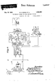
- FIG. 1 is a diagram of one form of our system
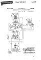
- Figs. 2 and 3 are diagrams of other forms.
- the elements and apparatus located at the left of the heavy broken line AA are located at the central station while the ap aratus at the right of said line are located at one of the distant stations, such as the home of a subscriber to the program service.
- a source of alternating current is available, from the output of a suitable amplifier or other apparatus.
- the plate element of this amplifier is designated by the numeral 4.
- B battery B is also located at the central station. Another source of direct current, such as a B eliminator or generator may be substituted for the B battery.
- the central ofiice output transformer comprising primary winding 1 and secondary windings 2 and 3, having condenser 5 inter osed therebetween, is disposed between t e source of alternating current and line conductors X and Y which extend between the central station and the distant station. These line conductors may be a pair of wires in a conventional communication cable.
- the output transformer is adapted to reduce the impedance of the source to a point where the termination of the line is made equal to the characteristic impedance of the line conductors.
- the B battery B is connected to the line conductors throu h transformer windings 2 and 3.
- Key 6 is also located at the central ofiice for the purpose of operating a remotely located relay at the receiving amplifiers at the distant stations, the contacts of said key opening and closing the filament circuit of the distant amplifier.
- the thermionic am lifier and accessory apparatus At the dist-anct station is located the thermionic am lifier and accessory apparatus.
- the ampli er disclosed is of the single stage push-pull type. It is to be understood, however, that an amplifier with more than one stage or an amplifier using the singletube-per-stage circuit may be employed.
- the ash-pull circuit is desirable in that it affords greater power output for the same plate and grid potentials and also reduces distortion to some extent by eliminating certain harmonics generated in the tubes.
- the structure of the amplifier at the distant station embodies choke coils 7 and 8 and condenser 9 for the puran input transformer comprising primary winding 13 and secondary windings 14 and 15; two thermionic tubes having grid elements 16 and 17, plate elements 18 and 19 and filament or cathode elements 20 and 21 respectively; an output transformer comprising primary windings 22 and 23 and secondar windin'g24; a dynamic speaker 25 inclu ing a voice coil 26 and a field coil 27, which, in the first form, is also employed as a retardation coil for the purpose of further segregating the input and output circuits of the amplifier; a power transformer 28 to supply filament current to the amplifier and having a primary winding 29 and a secondary winding 30; and a key 31 available for the use of the subscriber in opening and closing the filament circuit; a relay including winding 32 and spring contacts 33 and 34 for the purpose of opening and closing the filament circuit by a control from the central oflice.
- a condenser 35 is interposed between the filament and the plate potential tap on the output transformer for the purpose of further segregating the output and input circuits.
- a tapped resistance 37 is connected across the filament supply leads and having a center tap connected to the grid return for the fpurpose of preventing the amplification 0 any alternating current Cross hum which might be generated in the filament circuit.
- a grid bias resistance 38 is connected betweenthe filament and grid return.
- the filament circuit for the thermionic tubes of the amplifier may be conveniently supplied from the household source of alternating current.
- This circuit includes winding 30 of the power transformer, contacts 33 and 34 of relay 32-33-34, filaments 20 and 21 and the contacts of key 31..
- This circuit is closed and supplies current to the filaments as long as the relay is operated and the contacts of key 31 are closed.
- Key 31 is available to the use of the subscriber while the relay is energized by currents transmitted from the central station thereby making it possible for the operators at the central station to energize or de-energize the filament circuits of the distantly located amplifier as may seem desirable.
- the operation of relay 32333-1 will be further treated in the explanation of the control circuit.
- Grid supply circuit Grid supply potentials are generated for grids 16 and 17 by means of potentials created across grid bias resistance 38 through a path from positive battery 13 at the central office, contacts of key 6, winding 3 of central ofiice output transformer, line conductor Y, choke coil 8, choke coil 27, windings 22 and 23 of the output transformer, the space current paths of both tubes, resistance 37. resistance 38, choke coil 7, line conductor X, transformer winding 2 to negative battery B. This current sets up a voltage across resistance 38 which serves to keep the grids 16 and 17 at a negative potential at all times in respect to filaments 20 and 21 respectively.
- Plate supply circuit Plate potentials and currents are supplied to both plates through the identical circuit described in the paragraph headed Grid supply circuit.
- This potential causes a current to flow from tap 11 through winding 13 to oint N inducing a corresponding potentia of greater magnitude across windings 14 and 15, which is applied directly to grids 16 and 17.
- This potential is augmented by the normal amplifying action of the tubes and the resultmg potential created between plates 18 and 19 causes current to flow throu h windings 22 and 23 of the output trans ormer. By induction a current is thereby caused to circulate through the secondary winding 24 of the output transformer and the voice coil 26 of the d namic s eaker.
- this circuit embodies certain impedances which are common both to the input and the output circuit of the amplifier. Specifically line conductors X and Y are used for the transmission of operating potentials to the plate circuit and are also used for the transmission of alternating potentials to the input circuit. For this rea-- son it is necessary to incorporate means in the device for preventing the return of alternating currents generated in the output circuit to the input circuit.
- means are provided in this amplifier for maintaining the impedance of that part of the supply circuit which is disposed between the input and the output circuits of the amplifier at a high value in respect to alternating currents.
- this amplifier for maintaining the impedance of that part of the supply circuit which is disposed between the input and the output circuits of the amplifier at a high value in respect to alternating currents.
- condenser 9 and choke coils 7 and 8 comprising a conventional electrical filter, and choke coil 27.
- the choke coil 27 is shown to be a part of the dynamic speaker, a feature which will contribute considerably to economy in the manufacture of the appara- Manner Specifically these means intus.
- this choke coil will be the field coil of the speaker and its impedance is such that it will retard to a very great extent the passage of any currents due to unbalance potcutials set u between the supply tap on windings 22 an 23 and the filaments of the tubes.
- the impedance of condenser 9 has a low value in respect to alternating currents and oflers a path whereby any unbalance currents may readily return to the filament of the tubes without traversing the line conductors or the input circuit.
- choke coils 7 and 8 ofier an extremely high impedance to unbalance currents and according- 1y prevent the transmission of any such currents to the line or input circuit.
- a path of relatively low im dance is supplied by choke coils 7, 8 an '27 for the transmission of direct currents to the plate circuits of the tubes while condenser 9 has an infinite impedance for currents of this t pe and accordingly does not provide a tfi between line conductors X and Y.
- the two elements referred to provide means whereby direct currents for the purpose of maintaining the various elements of the tubes at operative potentials may be transmitted to the tubes w1th slight loss; whereby alternating currents generated in the plate circuit of the amplifier are prevented from returning to the grid circuit of the amplifier, thereby preventing undesirable regeneration effects; and whereby signal currents transmitted to the amplifier or line conductors X and Y are allowed to traverse the input circuit of the amplifier without attenuation caused by the various taps taken oil for the supply circuit.
- Condenser 12 is interposed between the filter 7-8-9 and the potentiometer 10 for the urpose of preventing1 the passage of supp y currents through t e potentiometer winding while at the same time allowing the passage of alternating signal currents to the input circuit of the am lifier.
- Condenser is provi ed at the central office for the purpose of allowing the passage of signal currents through windings 2 and 3 of the output transformer and for the purpose of preventing the passage of supply currents from the central ofiice battery B.
- Control relay circuit The control relay is energized by current transmit-ted from positive central ofiice battery B through contacts of key 6, winding 3, line conductor Y, choke coil 8, winding 32 of the control relay, choke coil 7, line con- Volume control operation
- signal currents traversing winding of the potentiometer set u a potential between tap 11 and point N. e magnitude of this potential is directly proportional to the resistance included between tap 11 and point N.
- ta 11 is moved along the length 0 the win ing to include a larger amount of resistance, the potential impressed across winding 13 is increased.
- tap 11 is moved to include a smaller amount of resistance, the potential impressed across winding 13 is decreased.
- a corresponding and proportional variation in potential is produced between grids 16 and 17.
- the ap aratus included in this form is similar to t at described in connection with the first form and the individual elements are disposed similarly in respect to each other with the exception that an input transformer and potentiometer, each having two windings separated by a condenser, are employed; and that the plate circuit retardation coil does not form a part of the speaker.
- the Pl'i'. mary windings of the input transformer are numbered 7a and 9a and the windings of the potentiometer are numbered 10a and 11a.
- the condensers employed in connection with the transformer winding and potentiometer are numbered respectively 8a and 12a. ⁇ Vith these exceptions the elements of the circuit are designated by the same numbers in the drawings as were employed in the case of the first form.
- Grid supply circuit Potentials for maintaining the grids at negative potentials with respect to the filaments are created between the terminals of resistance 38 due to the normal plate supply current which flows through a path from positive central otlice battery B, contacts of key 6, transformer winding 3, line conductor Y, potentiometer winding 11a, transformer winding 90, choke coil 27a, transformer windings 22 and 23, the space current paths of both tubes, resistance 37, resistance 38, transformer winding 7a, potentiometer winding 100:, line conductor X, transformer winding 2 to negative central ofiice battery B.
- Plate supply circuit Current supply for the plate circuits of the tubes is transmitted through the same tials are transmitted from the central station to the remote station along line conductors X and Y in a manner exactly similar to that described in connection with the first form.
- the potentiometer windings 10a and 11a cause alternating current to flow through these windings and through condenser 12a and set up between any two points on windings 10a and 11a alternating potentials proportional to the re sistance included between the two points.
- the alternating potentials between potentiometer taps'M and N cause current to How through transformer windings 7a and 9a and condenser 8a.
- induction a corresponding potential is generated in the secondary windings 14 and 15 and impressed on grids l6 and 17 This potential is amplified and delivered to the loud speaker in a manner similar to the first form.
- the combination including transformer windings 7a and 9a and condenser 8a perform a dual function.
- This combination takes the place of filter 789 shown in the first form and is effective in segregating the output circuit from the in put circuit.
- windings 7a and 9a comprise the primary of the input transformer. Cons1dering this combination of elements as a filter, windings 7a and 9a provide a path of high impedance to unbalance potentials generated in the plate circuit thereby preventing the return of any unbalance currents to the grid circuit; while at the same time a path of low impedance is provided for supply currents.
- Condenser 8a provides a path of high impedance to supply currents but allows the passage of alternating signal currents received trom the line conductors.
- Transformer windings 7a and 9a and potentiometer windings 10a and 11a are balanced in respect to the line in such a way that any small capacity effects existing between elements of the amplifier and ground will not produce an unbalanced condition of the line.
- the plate circuit retardation coil 27a is shown as a separate element and does not form a part of the speaker, which in this case is of the magnetic type.
- Control relay circuit The control relay is energized by currents transmitted from positive central ofiice battery B through contacts of key 6, trans- Cross Reference central oflice battery B. By operating key 6 relay 32-33-34 may be energized or deenergized, opening and closing the filament circuit.
- alternating potentials received from the line cause current to flow through the potentiometer windings 10a and 11a and condenser 12a, settin up between any two points along the lengt l of winding 10a and 11a alternating potentials proportional to the resistance included between the two points.
- Taps are taken 01f from windings 10a. and 11a in such a way that as the, potentiometer arms are moved a connection is made from taps M and N to difi'erent points along the length of windings 10a and.
- any increase in the resistance included between tap M and condenser 120 will be accompanied by a corres onding change in the resistance included etween tap N and condenser 12a. Accordingly as the potentiometer arms are moved to include a greater resistance between taps M and N, a greater potential is impressed across the input transformer; while as the potentiome-' ter arms are moved to include a less resistance a smaller potential is applied to the,
- the apparatus included in this form is similar to the first form and the disposition of the various elements in respect to each other is similar. to the arrangement of the first form with the exception that filter combination 789 shown in he first form is replaced by the. combination including transformer windings 7b and 8b and condenser 96; and that potentiometer 10l1 shown in the first form is replaced by potentiometer 10b11b. With these exceptions the elements of the circuit are designated by the same numbers as were applied to the corresponding elements in the first form.
- Filament circuit This circuit is similar to the first form.
- Grid supply circuit Grid supply potentials for maintaining the grid elements of the tubes at a negative bias in respect to the filaments are created between the terminals of resistance 38 due to the passage of the plate supply current which flows through a path from positive central ofiice battery B, contacts of key 6, transformer winding 3, line conductor Y, transformer winding 86, retardation coil 27, transformer windings 22 and 23, the space current paths of both tubes, resistance 37, resistance 38, transformer winding 76, line conductor X, transformer winding 2, to negative central oflice battery B.
- the combination including transformer windings 7'6 and 8?) and condenser 9b performs a dual purpose in acting as a segregatin unit for the se aration of the input and output circuits an also in forming a part of the input circuit for the delivery of the signal current to the grids of the tubes.
- Control relay circuit This circuit is similar to the first form.
- volume control operation The operation and construction of the volume control are similar to those described in connection with the previously outlined second form, except that the potentials generated between taps M and N are ap lied directly to grids 16 and 17 and are not elivered' to the tubes through the input transformer.
- the three embodiments of the invention disclosed successfully fulfill the objec'ts set forth.
- the form shown in Fig. 1 presents certain advantages in relation to the other g forms, but each of the other forms possesses lesser points of advantage in certain remeans tion can be made to have practically anyv constants which may be desirable in order to produce the most effective segregating properties.
- the filter employed is a part of the input transformer and when this input transformer constitutes the line termination, the impedance of the retardation coil is limited by the necessity of making the impedance of both coils in series e ual to the characteristic impedance of the ine. This disadvantage is overcome by usii a separate filter.
- a second advantage 0 the first form is that no supply current traverses the windings of the potentiometer effecting substantial economies in the n'ianufacture of this element.
- a third advantage exists in the fact that no supply current is allowed to traverse winding 13 of the input transformer thereby preventing undesirable saturation efl'ects.
- the form of the invention disclosed in F igi 2 has the advantage that the separate filter combination is eliminated with a corre-' sponding decrease in the cost of mannfac ture. Adequate segregating characteristics in the transformer windings 7a and 9a are maintained by placing the volume control on the line side of the transformer thereby maintaining the impedance of the transformer windin at a relatively high value.
- the form 0 the invention disclosed in Fig. 3 has the same advantages as Fig. 2 in relation to the elimination of the separate filter and has the additional advantage that no current is allowed to traverse the potentiometer windings enabling the construction ofthis element at a lower cost.
- Figs. 1 and 3 show the use of the field coil of the dynamic speaker as a retardation coil for the purpose of impeding the flow of unbalance currents from the plate circuit to the input circuit. This feature should result in desirable savings in manufacturing costs.
- the impedance ratio of the central oifice output transformer is such that the impedance of the source of signal current 4 is reflected through to the line at a value equal to the characteristic impedance of the line. It is a well known principle in transmission of alternating currents that under these conditions a mlnimum voltage level is re ired at the central station for the transmission of a maximum voltage level to the remote station.
- the signal currents will be transmitted from the central station to the remote station at a voltage level sufiiciently low to obviate the possibility of causing any cross talk" in neighboring conductors in the same communication cable, it being remembered that our system is especially adapted for use in program service sup lied by telephone companies wherein con uctors in conventional communication cables may be utilized for the transmission of sound or image-carrying currents as well as for the transmission of operating electro-motive forces for the remotely located amplifiers.
- alternating currents is meant to include all currents described in the'foregoing specification as sound-carrying, image-carrying or signal currents.
- space current path is meant to indicate the path of conductivity existing in a conventional vacuum tube between the plate and filament due to the flow of electrons between said two elements.
- a central station having available a source of direct current and a source of alternating current, a distantly located station, a thermionic am lifier at said distant station having grid, p ate, and cathode elements and including input elements, a pair of metallic conductors extending between said central station and said distant station, a circuit for said alternating current including said conductors and including said input elements, a circuit for said direct current also including said conductors and including the space current path of said amplifier, a resistance element at said distant station inserted in said direct current circuit for maintaining said grid element at operative bias potential with respect to said cathode element, a relay at said distant station having an actuatin coil and a pair of contacts which are close when said coil is energized, and a local source of electrical energy at said distant station for heating said cathode element, the coil of said relay bein connected to said direct current circuit and the contacts of said relay being inserted in a circuit connecting said local source to said cathode element
- a central station having available a source of direct current and a source of alternating current, a distantly located station, a thermionic amplifier at said distant station having grid, filament, and plate elements and including input elements, a pair of metallic conductors extending between said central station and said distant station, a circuit for said alternating current including said conductors and including said input elements, a circuit for said direct current also including said conductors and including the space current path of said amplifier.
- a coil at said central station coupled to said source of alternating currents, said coil being divided at its midpoint to form two equal sections thereof, said source of direct current being connected in series with and between said sections, a condenser connected in multiple with said source of direct current, the remainin terminal of said coil being connected to t e respective conductors of said pair.
- a central station having available a source of direct current and a source of alternating current, a. distantly located station, a thermionic amplifier at said distant station having "rid, filament, and plate elements and including input elements, a pair of metallic conductors extending between said central station and said distant station, coupling means at said central station connecting said source of alternating current and said source of direct current tosaid conductors, a coil at said distant station having two sections, a condenser connected in series with and between" said sections and the remaining ends of said sections bein connected to the respective conductors 0% said pair, said input elements being connected to said conductors, a condenser inserted in series with said input elements, the space current circuit of said amplifier being connected in parallel with said first mentioned condenser, a source of electrical energy local to said distant station for heating said filament element, a relay having an actuating coil and having electrical contacts connected in series withgaid local source, the coil of said relay being connected in parallel with said first mentioned con
- a central station having available a source of direct current and a source of alternating current, a distantly located station, a thermionic amplifier at said distant station having grid, filament, and plate elements and including input elements, a pair of metallic conductors extending between said central station and said distant station, a coil at said central station coupled to said source of alternating circuits, said coil being divided into'two equal sections, said source of direct current being connected in series with and between said sections, a condenser connected in parallel with said source of direct current, the remaining terminals of said coil being connected to the respective conductors of said pair, a coil at said distant station having two sections, a condenser connected in series with and between said sections and the remaining ends of said sections being connected to the respective conductors of said pair, said input elements being connected to said conductors, a condenser inserted in serice with said input elements, the space current circuit of said amplifier being connected in parallel with said second mentioned condenser, a source of electrical energy 10-
Description
xaminer Reference D. B. HARRIS ET AL may 16 1933 TRANSMISSION SYSTEM FOR SOUND CARRYING CURRENTS- Filed Oct. 20, 1936 Sheets-Sheet l 15 erfi om' ewewm Examiner 6 J 3 ,7 w I wn m p e 6 m 2: S3 W V H W m 3 K m a w 4 Im aha z: JWJ M m C D. B. HARRIS ET AL s T N E R R u C G N I v M O l o w 2 s W at 00 F0 mm 9 T n HF S N 0 I s s I M s N A R T .QQQ'OQOOOO In D May 16, 1933 txaminer e C n nu r rm 9 S S 0 r C May 16, 1933.
D. B. HARRIS ET AL TRANSMISSION SYSTEM FOR SOUND CARRYING CURRENTS 3 Sheets-Sheet 3 Filed 001:. 20, 1950 Ji WWWM i Patented May 16, 1933 UNITED STATES PATENT OFFICE DONALD B. HARRIS AND ORVILLE W. KNAUSS, OF ST. PAUL, BUNN'ESOTA, ASSIGNOBS, BY DIRECT AND MESNE ASSIGNMENTS, '10 PROGRAM SERVICE comm, 01' 8'1. PAUL, MINNESOTA, A CORPORATION 01 DELAWARE I TRANSMISSION SYSTEM FOR SOUND-CARRYING GURBENTS Application filed October 20, 1930. Serial No. 489,888.
number of distant stations, such as subscrib-' ers homes, and wherein conductors in con ventional communication systems could be conveniently utilized to transmit not only the sound-carrying currents, but, in conjunction with ground, other elect-ro-motive forces for operating amplifiers located at the distant stations.
As pointed out in our said patent, one of the important advantages of the original system was to eliminate interference caused by induction of energy into other conductors neighboring or in the same cable with the conductors utilized in our system, which induction is often referred to as cross talk. However, cross talk or induction was not entirely overcome due to the fact that the line conductors of the original system were not balanced with respect to ground.
Another objection to the original system was that a small amount of low frequency regeneration resulted in the system due to a feed-back from the plate circuit to the grid circuit and through the medium of a potential generated along the plate circuit side of the line.
In our joint application entitled Transmission': .system for sound-carrying currents, S. N. 460,882, filed June 13th, 1930, we disclosed an improved transmission system for sound-carrying and image-carrying currents which lessened the said objectionable features of said original system. In said improved system, potentials for maintaining the grid at an operative potential with respect to the filament element were supplied from the central ofiice through a circuit in- 59 eluding one of the line conductors in conunction with ground. The line conductors of this system were adequately balanced with respect to ground and efiicient means were provided for preventing undesirable re- 5 generation effects. In the said improved system, under some conditions, however, noise induction of small magnitude resulted in the line transmitting the program service due to a difference between the ground potentials at the central and the remote stations and due to the impossibility of maintaming the terminating impedances in a condition of perfect balance. The installation costs of said improved system were high due to the necessity of making a connection to ground at the subscribers stations.
In both the ori inal and said improved systems, because of the necessity of ground connectlons in conjunction with the several circuits included in the system' and dueto the high plate potentials required in connection with the amplifier, some danger is presented to workmen installing or servicing neighboring telephone or communication lines, and the said high potentials may break down the protective devices associated with the conductors of our system at either the central or distant stations.
It is an object of our present invention to provide an economical and improved system of the class described utilizing apair of conductors between a central and a distant station for transmission of sound and image-carryin currents as well as grid and late potentia wherein the objectionable eatures of said original system and said improved system are obviated; wherein the system is simplified and may be installed at less cost; wherein sound or image-carrying currents are transmitted from the central station to the remote station with a minimum loss of energy, and wherein the pair of line conductors employed are isolated from ground thereby eliminating all chance of noise inductions.
It is a further object to provide a system of the class described wherein conductors, such as, for example, a pair of conductors in a conventional communication cable may be utilized for transmitting soundor imagecarrying currents from a central station to a distant station; wherein the same conductors transmit electro-motive forces for maintaining the plate element of the amplifier at an operative potential in respect to the filament and wherein potentials for maintaining the grid element of the amplifier at an operative potential in respect to the filament element are created in the remotely located amplifier by means of electro-motive forces generated across a resistance inserted in the supply circuit, including the central oflice source of direct current and said line conductors. In our present invention all signal arlllg supply circuits may be isolated from on Another object is to provide a s stem wherein the safety hazards previous y referred to are eliminated throughout the system.
These and other objects and advantages of the invention will be fullv set forth in the following description made in connection with the accompany drawings, in which like reference characters refer to similar parts throughout the several views, and in which Fig. 1 is a diagram of one form of our system, and
Figs. 2 and 3 are diagrams of other forms.
Referring to the first form of the invention, illustrated in Fig. 1, the elements and apparatus located at the left of the heavy broken line AA are located at the central station while the ap aratus at the right of said line are located at one of the distant stations, such as the home of a subscriber to the program service. At the central station a source of alternating current is available, from the output of a suitable amplifier or other apparatus. In the drawings, the plate element of this amplifier is designated by the numeral 4. B battery B is also located at the central station. Another source of direct current, such as a B eliminator or generator may be substituted for the B battery. The central ofiice output transformer, comprising primary winding 1 and secondary windings 2 and 3, having condenser 5 inter osed therebetween, is disposed between t e source of alternating current and line conductors X and Y which extend between the central station and the distant station. These line conductors may be a pair of wires in a conventional communication cable. The output transformer is adapted to reduce the impedance of the source to a point where the termination of the line is made equal to the characteristic impedance of the line conductors. The B battery B is connected to the line conductors throu h transformer windings 2 and 3. Key 6 is also located at the central ofiice for the purpose of operating a remotely located relay at the receiving amplifiers at the distant stations, the contacts of said key opening and closing the filament circuit of the distant amplifier.
At the dist-anct station is located the thermionic am lifier and accessory apparatus. The ampli er disclosed is of the single stage push-pull type. It is to be understood, however, that an amplifier with more than one stage or an amplifier using the singletube-per-stage circuit may be employed. The ash-pull circuit is desirable in that it affords greater power output for the same plate and grid potentials and also reduces distortion to some extent by eliminating certain harmonics generated in the tubes.
In particular the structure of the amplifier at the distant station embodies choke coils 7 and 8 and condenser 9 for the puran input transformer comprising primary winding 13 and secondary windings 14 and 15; two thermionic tubes having grid elements 16 and 17, plate elements 18 and 19 and filament or cathode elements 20 and 21 respectively; an output transformer comprising primary windings 22 and 23 and secondar windin'g24; a dynamic speaker 25 inclu ing a voice coil 26 and a field coil 27, which, in the first form, is also employed as a retardation coil for the purpose of further segregating the input and output circuits of the amplifier; a power transformer 28 to supply filament current to the amplifier and having a primary winding 29 and a secondary winding 30; and a key 31 available for the use of the subscriber in opening and closing the filament circuit; a relay including winding 32 and spring contacts 33 and 34 for the purpose of opening and closing the filament circuit by a control from the central oflice.
A condenser 35 is interposed between the filament and the plate potential tap on the output transformer for the purpose of further segregating the output and input circuits. A tapped resistance 37 is connected across the filament supply leads and having a center tap connected to the grid return for the fpurpose of preventing the amplification 0 any alternating current Cross hum which might be generated in the filament circuit. A grid bias resistance 38 is connected betweenthe filament and grid return.-
In describing our system, the apparatus and elements utilized will be described in conjunction with the several circuits between the central station and the subscriber's home: a
F'Zlawwnt circuit The filament circuit for the thermionic tubes of the amplifier may be conveniently supplied from the household source of alternating current. This circuit includes winding 30 of the power transformer, contacts 33 and 34 of relay 32-33-34, filaments 20 and 21 and the contacts of key 31.. This circuit is closed and supplies current to the filaments as long as the relay is operated and the contacts of key 31 are closed. Key 31 is available to the use of the subscriber while the relay is energized by currents transmitted from the central station thereby making it possible for the operators at the central station to energize or de-energize the filament circuits of the distantly located amplifier as may seem desirable. The operation of relay 32333-1 will be further treated in the explanation of the control circuit.
Grid supply circuit Grid supply potentials are generated for grids 16 and 17 by means of potentials created across grid bias resistance 38 through a path from positive battery 13 at the central office, contacts of key 6, winding 3 of central ofiice output transformer, line conductor Y, choke coil 8, choke coil 27, windings 22 and 23 of the output transformer, the space current paths of both tubes, resistance 37. resistance 38, choke coil 7, line conductor X, transformer winding 2 to negative battery B. This current sets up a voltage across resistance 38 which serves to keep the grids 16 and 17 at a negative potential at all times in respect to filaments 20 and 21 respectively.
Plate supply circuit Plate potentials and currents are supplied to both plates through the identical circuit described in the paragraph headed Grid supply circuit.
Signal circuit Alternating potentials generated by the central oflice amplifier are impressed on winding 1 of the central office output transformer causing current to flow through this winding. In turn this current induces a potential across windings 2 and 3. This potential causes current to flow from point I shown on the drawings through line conductor X, condenser 12, potentiometer winding 10, line conductor Y, to the point Q Reference shown on the drawings. This current in turn creates a potential along the length of potentiometer winding 10 and accordingly generates a proportional potential between tap 11 and line conductor Y at point N. This potential causes a current to flow from tap 11 through winding 13 to oint N inducing a corresponding potentia of greater magnitude across windings 14 and 15, which is applied directly to grids 16 and 17. This potential is augmented by the normal amplifying action of the tubes and the resultmg potential created between plates 18 and 19 causes current to flow throu h windings 22 and 23 of the output trans ormer. By induction a current is thereby caused to circulate through the secondary winding 24 of the output transformer and the voice coil 26 of the d namic s eaker.
It wil be note that this circuit embodies certain impedances which are common both to the input and the output circuit of the amplifier. Specifically line conductors X and Y are used for the transmission of operating potentials to the plate circuit and are also used for the transmission of alternating potentials to the input circuit. For this rea-- son it is necessary to incorporate means in the device for preventing the return of alternating currents generated in the output circuit to the input circuit. In the case of a push-pull amplifier of this type, potentials in the plate circuit to which the supply circuit is accessible are very small, and are lim ited to small unbalance potentials generated between the supply tap on windings 22 and 23 and the filament, due to differences in the electrical properties of windings 22 and 23 or due to a dissimilarity in the amplifying properties of the tubes. These potentials, however, exist to some extent, and if a path of low impedance were provided along the supply circuit, a certain amount of unbalance current would flow from the supply tap on windings 22 and 23 through line conductor Y, windings 2 and 3 of the central office output transformer, line conductor X and winding 13 of the input transformer, inducing a corresponding potential on grids 16 and 17 and cause undesirable regeneration effects.
In order to prevent effects of this kind, means are provided in this amplifier for maintaining the impedance of that part of the supply circuit which is disposed between the input and the output circuits of the amplifier at a high value in respect to alternating currents. clude: the combination of condenser 9 and choke coils 7 and 8 comprising a conventional electrical filter, and choke coil 27.
In the first form the choke coil 27 is shown to be a part of the dynamic speaker, a feature which will contribute considerably to economy in the manufacture of the appara- Manner Specifically these means intus. Preferably this choke coil will be the field coil of the speaker and its impedance is such that it will retard to a very great extent the passage of any currents due to unbalance potcutials set u between the supply tap on windings 22 an 23 and the filaments of the tubes.
In the filter combination 78-9 the impedance of condenser 9 has a low value in respect to alternating currents and oflers a path whereby any unbalance currents may readily return to the filament of the tubes without traversing the line conductors or the input circuit. On the contrary, choke coils 7 and 8 ofier an extremely high impedance to unbalance currents and according- 1y prevent the transmission of any such currents to the line or input circuit. At the same time, a path of relatively low im dance is supplied by choke coils 7, 8 an '27 for the transmission of direct currents to the plate circuits of the tubes while condenser 9 has an infinite impedance for currents of this t pe and accordingly does not provide a tfi between line conductors X and Y.
n combination, the two elements referred to provide means whereby direct currents for the purpose of maintaining the various elements of the tubes at operative potentials may be transmitted to the tubes w1th slight loss; whereby alternating currents generated in the plate circuit of the amplifier are prevented from returning to the grid circuit of the amplifier, thereby preventing undesirable regeneration effects; and whereby signal currents transmitted to the amplifier or line conductors X and Y are allowed to traverse the input circuit of the amplifier without attenuation caused by the various taps taken oil for the supply circuit.
' Condenser 12 is interposed between the filter 7-8-9 and the potentiometer 10 for the urpose of preventing1 the passage of supp y currents through t e potentiometer winding while at the same time allowing the passage of alternating signal currents to the input circuit of the am lifier.
Condenser is provi ed at the central office for the purpose of allowing the passage of signal currents through windings 2 and 3 of the output transformer and for the purpose of preventing the passage of supply currents from the central ofiice battery B.
Control relay circuit The control relay is energized by current transmit-ted from positive central ofiice battery B through contacts of key 6, winding 3, line conductor Y, choke coil 8, winding 32 of the control relay, choke coil 7, line con- Volume control operation As discussed briefly in the description of the signal circuit, signal currents traversing winding of the potentiometer set u a potential between tap 11 and point N. e magnitude of this potential is directly proportional to the resistance included between tap 11 and point N. Accordin 1y, as ta 11 is moved along the length 0 the win ing to include a larger amount of resistance, the potential impressed across winding 13 is increased. Conversely, if tap 11 is moved to include a smaller amount of resistance, the potential impressed across winding 13 is decreased. A corresponding and proportional variation in potential is produced between grids 16 and 17.
Referring to the second form of the invcntion illustrated in Fig. 2, the ap aratus included in this form is similar to t at described in connection with the first form and the individual elements are disposed similarly in respect to each other with the exception that an input transformer and potentiometer, each having two windings separated by a condenser, are employed; and that the plate circuit retardation coil does not form a part of the speaker. The Pl'i'. mary windings of the input transformer are numbered 7a and 9a and the windings of the potentiometer are numbered 10a and 11a. The condensers employed in connection with the transformer winding and potentiometer are numbered respectively 8a and 12a. \Vith these exceptions the elements of the circuit are designated by the same numbers in the drawings as were employed in the case of the first form.
In describing this form, only such circuits will be treated in detail-as deviate from the corresponding circuits outlined in the description of the first form.
Filament circuit This circuit is similar to the first form.
Grid supply circuit Potentials for maintaining the grids at negative potentials with respect to the filaments are created between the terminals of resistance 38 due to the normal plate supply current which flows through a path from positive central otlice battery B, contacts of key 6, transformer winding 3, line conductor Y, potentiometer winding 11a, transformer winding 90, choke coil 27a, transformer windings 22 and 23, the space current paths of both tubes, resistance 37, resistance 38, transformer winding 7a, potentiometer winding 100:, line conductor X, transformer winding 2 to negative central ofiice battery B.
Plate supply circuit Current supply for the plate circuits of the tubes is transmitted through the same tials are transmitted from the central station to the remote station along line conductors X and Y in a manner exactly similar to that described in connection with the first form. At the remote station signal potentials impressed on. the potentiometer windings 10a and 11a cause alternating current to flow through these windings and through condenser 12a and set up between any two points on windings 10a and 11a alternating potentials proportional to the re sistance included between the two points. The alternating potentials between potentiometer taps'M and N cause current to How through transformer windings 7a and 9a and condenser 8a. By induction a corresponding potential is generated in the secondary windings 14 and 15 and impressed on grids l6 and 17 This potential is amplified and delivered to the loud speaker in a manner similar to the first form.
In this form the combination including transformer windings 7a and 9a and condenser 8a perform a dual function. This combination takes the place of filter 789 shown in the first form and is effective in segregating the output circuit from the in put circuit. In addition windings 7a and 9a comprise the primary of the input transformer. Cons1dering this combination of elements as a filter, windings 7a and 9a provide a path of high impedance to unbalance potentials generated in the plate circuit thereby preventing the return of any unbalance currents to the grid circuit; while at the same time a path of low impedance is provided for supply currents. Condenser 8a provides a path of high impedance to supply currents but allows the passage of alternating signal currents received trom the line conductors. Transformer windings 7a and 9a and potentiometer windings 10a and 11a are balanced in respect to the line in such a way that any small capacity effects existing between elements of the amplifier and ground will not produce an unbalanced condition of the line.
In this form the plate circuit retardation coil 27a is shown as a separate element and does not form a part of the speaker, which in this case is of the magnetic type.
Control relay circuit The control relay is energized by currents transmitted from positive central ofiice battery B through contacts of key 6, trans- Cross Reference central oflice battery B. By operating key 6 relay 32-33-34 may be energized or deenergized, opening and closing the filament circuit.
Volume control operation As outlined previously in the discussion of the signal circuit, alternating potentials received from the line cause current to flow through the potentiometer windings 10a and 11a and condenser 12a, settin up between any two points along the lengt l of winding 10a and 11a alternating potentials proportional to the resistance included between the two points. Taps are taken 01f from windings 10a. and 11a in such a way that as the, potentiometer arms are moved a connection is made from taps M and N to difi'erent points along the length of windings 10a and. 114, such that any increase in the resistance included between tap M and condenser 120 will be accompanied by a corres onding change in the resistance included etween tap N and condenser 12a. Accordingly as the potentiometer arms are moved to include a greater resistance between taps M and N, a greater potential is impressed across the input transformer; while as the potentiome-' ter arms are moved to include a less resistance a smaller potential is applied to the,
input transformer.
Referring to the third form of the invention disclosed in Fig. 3, the apparatus included in this form is similar to the first form and the disposition of the various elements in respect to each other is similar. to the arrangement of the first form with the exception that filter combination 789 shown in he first form is replaced by the. combination including transformer windings 7b and 8b and condenser 96; and that potentiometer 10l1 shown in the first form is replaced by potentiometer 10b11b. With these exceptions the elements of the circuit are designated by the same numbers as were applied to the corresponding elements in the first form.
In describing the operation of this form of the invention only such circuits will be treated in detail as deviate from the corresponding circuits of the first form.
" Filament circuit This circuit is similar to the first form. Grid supply circuit Grid supply potentials for maintaining the grid elements of the tubes at a negative bias in respect to the filaments are created between the terminals of resistance 38 due to the passage of the plate supply current which flows through a path from positive central ofiice battery B, contacts of key 6, transformer winding 3, line conductor Y, transformer winding 86, retardation coil 27, transformer windings 22 and 23, the space current paths of both tubes, resistance 37, resistance 38, transformer winding 76, line conductor X, transformer winding 2, to negative central oflice battery B.
. Plate supply circuit tentiometer windings 10b and 11b and ac cordingly set u between any two points along the lengt of windings 10b and 11b alternating signal potentials directly proportional to the resistance included between the oints. These potentials are applied direct y to grids 16 and 17, and are amplified and delivered to the loud speaker in a manner similar to that described in connection with the first form.
As in the case of the previously described second form, the combination including transformer windings 7'6 and 8?) and condenser 9b performs a dual purpose in acting as a segregatin unit for the se aration of the input and output circuits an also in forming a part of the input circuit for the delivery of the signal current to the grids of the tubes.
Control relay circuit This circuit is similar to the first form.
Volume control operation The operation and construction of the volume control are similar to those described in connection with the previously outlined second form, except that the potentials generated between taps M and N are ap lied directly to grids 16 and 17 and are not elivered' to the tubes through the input transformer.
From the foregoing description it will be seen that the three embodiments of the invention disclosed successfully fulfill the objec'ts set forth. Of the three forms disclosed, the form shown in Fig. 1 presents certain advantages in relation to the other g forms, but each of the other forms possesses lesser points of advantage in certain remeans tion can be made to have practically anyv constants which may be desirable in order to produce the most effective segregating properties. When the filter employed is a part of the input transformer and when this input transformer constitutes the line termination, the impedance of the retardation coil is limited by the necessity of making the impedance of both coils in series e ual to the characteristic impedance of the ine. This disadvantage is overcome by usii a separate filter. A second advantage 0 the first form is that no supply current traverses the windings of the potentiometer effecting substantial economies in the n'ianufacture of this element. A third advantage exists in the fact that no supply current is allowed to traverse winding 13 of the input transformer thereby preventing undesirable saturation efl'ects.
The form of the invention disclosed in F igi 2 has the advantage that the separate filter combination is eliminated with a corre-' sponding decrease in the cost of mannfac ture. Adequate segregating characteristics in the transformer windings 7a and 9a are maintained by placing the volume control on the line side of the transformer thereby maintaining the impedance of the transformer windin at a relatively high value.
The form 0 the invention disclosed in Fig. 3 has the same advantages as Fig. 2 in relation to the elimination of the separate filter and has the additional advantage that no current is allowed to traverse the potentiometer windings enabling the construction ofthis element at a lower cost.
Figs. 1 and 3 show the use of the field coil of the dynamic speaker as a retardation coil for the purpose of impeding the flow of unbalance currents from the plate circuit to the input circuit. This feature should result in desirable savings in manufacturing costs.
In the three embodiments of the invention disclosed it is to be borne in mind that the impedance ratio of the central oifice output transformer is such that the impedance of the source of signal current 4 is reflected through to the line at a value equal to the characteristic impedance of the line. It is a well known principle in transmission of alternating currents that under these conditions a mlnimum voltage level is re ired at the central station for the transmission of a maximum voltage level to the remote station. For this reason in the three enibodiments of the invention disclosed the signal currents will be transmitted from the central station to the remote station at a voltage level sufiiciently low to obviate the possibility of causing any cross talk" in neighboring conductors in the same communication cable, it being remembered that our system is especially adapted for use in program service sup lied by telephone companies wherein con uctors in conventional communication cables may be utilized for the transmission of sound or image-carrying currents as well as for the transmission of operating electro-motive forces for the remotely located amplifiers.
In the appended claims the term alternating currents is meant to include all currents described in the'foregoing specification as sound-carrying, image-carrying or signal currents. The term space current path is meant to indicate the path of conductivity existing in a conventional vacuum tube between the plate and filament due to the flow of electrons between said two elements.
What is claimed is:
1. In transmission systems for alternating current, a central station having available a source of direct current and a source of alternating current, a distantly located station, a thermionic am lifier at said distant station having grid, p ate, and cathode elements and including input elements, a pair of metallic conductors extending between said central station and said distant station, a circuit for said alternating current including said conductors and including said input elements, a circuit for said direct current also including said conductors and including the space current path of said amplifier, a resistance element at said distant station inserted in said direct current circuit for maintaining said grid element at operative bias potential with respect to said cathode element, a relay at said distant station having an actuatin coil and a pair of contacts which are close when said coil is energized, and a local source of electrical energy at said distant station for heating said cathode element, the coil of said relay bein connected to said direct current circuit and the contacts of said relay being inserted in a circuit connecting said local source to said cathode element.
2. In transmission systems for alternating current, a central station having available a source of direct current and a source of alternating current, a distantly located station, a thermionic amplifier at said distant station having grid, filament, and plate elements and including input elements, a pair of metallic conductors extending between said central station and said distant station, a circuit for said alternating current including said conductors and including said input elements, a circuit for said direct current also including said conductors and including the space current path of said amplifier. a coil at said central station coupled to said source of alternating currents, said coil being divided at its midpoint to form two equal sections thereof, said source of direct current being connected in series with and between said sections, a condenser connected in multiple with said source of direct current, the remainin terminal of said coil being connected to t e respective conductors of said pair.
3. In transmission systems for alternating current, a central station having available a source of direct current and a source of alternating current, a. distantly located station, a thermionic amplifier at said distant station having "rid, filament, and plate elements and including input elements, a pair of metallic conductors extending between said central station and said distant station, coupling means at said central station connecting said source of alternating current and said source of direct current tosaid conductors, a coil at said distant station having two sections, a condenser connected in series with and between" said sections and the remaining ends of said sections bein connected to the respective conductors 0% said pair, said input elements being connected to said conductors, a condenser inserted in series with said input elements, the space current circuit of said amplifier being connected in parallel with said first mentioned condenser, a source of electrical energy local to said distant station for heating said filament element, a relay having an actuating coil and having electrical contacts connected in series withgaid local source, the coil of said relay being connected in parallel with said first mentioned condenser.
4. The structure defined in claim 3 and a switch at said central station connected in series with said source of direct current whereby the supply of direct current to the space current circuit of said amplifier and to said relay coil may be simultaneously controlled.
5. In transmission systems for alternating current, a central station having available a source of direct current and a source of alternating current, a distantly located station, a thermionic amplifier at said distant station having grid, filament, and plate elements and including input elements, a pair of metallic conductors extending between said central station and said distant station, a coil at said central station coupled to said source of alternating circuits, said coil being divided into'two equal sections, said source of direct current being connected in series with and between said sections, a condenser connected in parallel with said source of direct current, the remaining terminals of said coil being connected to the respective conductors of said pair, a coil at said distant station having two sections, a condenser connected in series with and between said sections and the remaining ends of said sections being connected to the respective conductors of said pair, said input elements being connected to said conductors, a condenser inserted in serice with said input elements, the space current circuit of said amplifier being connected in parallel with said second mentioned condenser, a source of electrical energy 10- cal to said distant station for heating said filament element, a relay having an actuating coil and having electrical contacts connected in series with said local source, the coil of said relay being connected in parallel with said first mentioned condenser.
In testimony whereof we aflix our signatures.
DONALD B. HARRIS. O. W. KNAUSS.
meme
Priority Applications (1)
| Application Number | Priority Date | Filing Date | Title |
|---|---|---|---|
| US489882A US1908896A (en) | 1930-10-20 | 1930-10-20 | Transmission system for sound-carrying currents |
Applications Claiming Priority (1)
| Application Number | Priority Date | Filing Date | Title |
|---|---|---|---|
| US489882A US1908896A (en) | 1930-10-20 | 1930-10-20 | Transmission system for sound-carrying currents |
Publications (1)
| Publication Number | Publication Date |
|---|---|
| US1908896A true US1908896A (en) | 1933-05-16 |
Family
ID=23945663
Family Applications (1)
| Application Number | Title | Priority Date | Filing Date |
|---|---|---|---|
| US489882A Expired - Lifetime US1908896A (en) | 1930-10-20 | 1930-10-20 | Transmission system for sound-carrying currents |
Country Status (1)
| Country | Link |
|---|---|
| US (1) | US1908896A (en) |
-
1930
- 1930-10-20 US US489882A patent/US1908896A/en not_active Expired - Lifetime
Similar Documents
| Publication | Publication Date | Title |
|---|---|---|
| US2307771A (en) | Carrier current communication system | |
| US2288049A (en) | Telephone set circuit | |
| US1908896A (en) | Transmission system for sound-carrying currents | |
| US1992774A (en) | Alternating current transmission system such as telephone systems incorporating echosuppressors | |
| US2282403A (en) | Transmission system | |
| US2000190A (en) | Radio receiving system | |
| US2345026A (en) | Automatic level control | |
| US1919719A (en) | Transmission system for sound carrying currents | |
| US1953465A (en) | Distortion reduction in signaling systems | |
| GB397551A (en) | Improvements in electrical impedance networks and amplifiers | |
| US2101243A (en) | Telegraph signal repeating system | |
| US1855303A (en) | Multiple coaxial conductor system | |
| US1516519A (en) | Electrical transformer | |
| US1922415A (en) | Electrical-including radio-apparatus | |
| US1700393A (en) | Radio frequency amplification circuits | |
| US2149637A (en) | Public address system | |
| US2037546A (en) | Transmission network | |
| US1801774A (en) | Radio signaling system | |
| US2112446A (en) | Means for remote tuning of radio receivers | |
| US1733194A (en) | Nesota | |
| US1813775A (en) | Means for preventing retroactive effects in audion amplifier circuits | |
| US1942551A (en) | Power supply system for electron tube systems | |
| US2080082A (en) | Commutating balanced multiplex telephony | |
| US1412103A (en) | Service-observing set | |
| US1129959A (en) | System for amplifying electric waves. |