US1908892A - Drying apparatus - Google Patents
Drying apparatus Download PDFInfo
- Publication number
- US1908892A US1908892A US477358A US47735830A US1908892A US 1908892 A US1908892 A US 1908892A US 477358 A US477358 A US 477358A US 47735830 A US47735830 A US 47735830A US 1908892 A US1908892 A US 1908892A
- Authority
- US
- United States
- Prior art keywords
- housing
- tube
- tubes
- drier
- casing
- Prior art date
- Legal status (The legal status is an assumption and is not a legal conclusion. Google has not performed a legal analysis and makes no representation as to the accuracy of the status listed.)
- Expired - Lifetime
Links
Images
Classifications
-
- F—MECHANICAL ENGINEERING; LIGHTING; HEATING; WEAPONS; BLASTING
- F26—DRYING
- F26B—DRYING SOLID MATERIALS OR OBJECTS BY REMOVING LIQUID THEREFROM
- F26B21/00—Arrangements or duct systems, e.g. in combination with pallet boxes, for supplying and controlling air or gases for drying solid materials or objects
- F26B21/006—Arrangements or duct systems, e.g. in combination with pallet boxes, for supplying and controlling air or gases for drying solid materials or objects the gas supply or exhaust being effected through hollow spaces or cores in the materials or objects, e.g. tubes, pipes, bottles
- F26B21/008—Arrangements or duct systems, e.g. in combination with pallet boxes, for supplying and controlling air or gases for drying solid materials or objects the gas supply or exhaust being effected through hollow spaces or cores in the materials or objects, e.g. tubes, pipes, bottles the objects being flexible articles, which may be blown up by the drying gas, e.g. tubes, sausage casings
Description
M y 1933- H. E. DIETRICH ET AL DRYING APPARATUS 2 Sheets-Sheet 1 FiledAug. 23, 1930 Q @Mmwhk WW @I' May 16, 1933. H. E. DIETRICH ET AL 1,908,892
DRYING APPARATUS Filed Aug. 23, 1930 2 Sheets-Sheet 2 their contents are transferred to a humidifier Patented May 16, 1933 UNITED s'rArEs PATENT OFFICE HAROLD E. DIETRICH AND ALFRED G. HEWITT, OF CHTCAGO, ILLINOIS, ASSIGNORS TO THE VISKING SORPORATION, OF CHICAGO, ILLINOIS, A CORPORATION OF ILLINOIS DRYING APPARATUS Application filed August 23, 1930. Serial No. 477,358.
The invention relates to drying apparatus, and particularly to apparatus for drying iausage casings or tubes formed from celluose- Cellulose sausage casings or tubes are formed from a viscose which is obtained by practicing the method described in United States Letters Patent 1,612,508 granted to William F. Hendersonand Harold E. Dietrich, December 28, 1926. The viscose is extruded through an annular orifice to form the tubing and the tubing is then subjected to coagulating and regenerating baths, the excess coagulating and regenerating liquids being washed from the tubing in a bath of water. The washed tube is passed through a bath of some hygroscopic agent, preferably glycerine, and is then dried in such manner that it will not become brittle and, yet, will not be so'wet that it will not slip readily on the stufi'er horn of a stuifing machine.
The present invention relates particularly to the drying apparatus. In practice, the tubing is stored in sliver cans when it passes from the glycerine bath, and these cans with placed at one end of the drying a paratus. A plurality of lengths of the tu ing are pulled through the drier and are subjected to the drying process, after which the succeeding lengths of the tubes are subjected to the same treatment. In other words, the drying of the tubes is a step by step process and as the tubes are inflated duringthe drying operation the sections in the drier are severed from the tubing in the humidifier. .To indate the sections, compressed air is introduced in one'end of each section, the other end of the section being closed by a stopper.
Apparatus embodying the present invention preferably comprises fora-minous confining tubes for the casing sections, the confining tubes extending the entire length of the drier and being slidably mounted therein so that they may be removed for repairs, etc. At the discharge ends of the tubes, improved means is provided for securing the forward ends of the casing sections "to the means whereby compressed air is introduced into the sections. The construction is such that trated, the reference character the casing sections will not be in ured during the drying process, nor will they be injured when they are withdrawn through the discharge openings of the tubes.
Many other objects and advantages ofthe invention will become apparent as the following detailed description progresses, reference being had to the accompanying drawings, wherein:
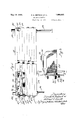
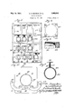
Figure 1 is a side elevation, partly in section, of a drier which embodies the invention; Fig. 2 is an elevation of the discharge end of the drier, certain parts thereof being omitted to illustrate the details of construction; Fig. 3 is an enlarged section taken substantially on line 3-3 of Fig. 2; Fig. 4: is a front elevation of one of a plurality of end plates which form the end wall at the discharge end of the drier; Fig. 5 is a section taken on line 55 of Fig. 3; Fig. 6 is a fragmentary enlarged longitudinal section through one end of one of a plurality of casing confining tubes provided in the drier, and Fig. 7 is a transverse section taken through one of the confining tubes.
Referring to the drawings wherein a preferred embodiment of the invention is illus- 10 designates generally the housing of a drier which comprises side walls 11, a top wall 12, a bottom wall 13 and end walls 14 and 15, the end walls 14 and 15 being at the discharge and loading ends of convenience, the housing 10 is mounted on standards 16.
The end wall 14' comprises a plate vided with rectangular apertures 18. These apertures are normally closed by rectangular plates 19 which are secured to the plate 17 y screws 20. Detachably secured by bolts or screws 21 to the back surface of each of the plates 19 is a rectangular plate 23 which is soldered to a ferrule 24 fixed to the end of a foraminous tube 25 which extends from the wall 14 into one of a plurality of apertures 26 provided in the wall 15. The screws 21 pass through the plates 19 and 23 and are screw-threaded into nuts 21a whichare soldered or brazed to the back surfaces of the plates 23. Y
the drier, respectively. For
17 proits Each of the tubes is provided with ferrules 24 at each end thereof (see Fig. 1). As
illustrated in Figs. 6 and 7, the walls of the ferrules are U-shape in cross-section and are clamped upon the ends of the tubes 25.
Each ferrule is provided with outwardly pronal seam which comprises flanges of the mesh projecting up between the angle irons 28 (see Fig. 7). The flanges and the lugs are preferably riveted to the angle irons 28. Y
The angle irons 28 are slidably mounted in guides or rails 30 which are secured to the.
The ferrules 24 adjacent the wall 15 are alined with the apertures 26 therein and the arrangement is such that when a section 33 of tubing or sausage casing has been drawn into one of the tubes, a stopper 34 may be inserted in the tube to cooperate with the associated ferrule adjacent the wall 15 in such manner that the wall of the tube is clamped between the ferrule and the stopper and that end of the tube is sealed.
Each of the plates 19 carries an im roved collet device 36 comprising a pair 0 semi-.
Iii the operation of the apparatus, when a section of sausage casing is drawn through one of the tubes 25 from the wall 15 to the wall 14, the forward end of the tube is drawn through the associated plate 19, as indicated in Fig. 1, andthe collet members associated with that plate are then brought into their closed positions. A stopper 45 is then inserted in that end of the sausage casing and clamps the wall of the casing between itself and the collet members. The stoppers 45 have tubes 46 projecting therethrough, which tubes 46 are connected by flexible tubes 47, or the equivalent, to a source of fluid pressure, preferably compressed air, which has been heated.
The compressed air inflates the casing section as the other end thereof is closed by a stopper 34. The pressure to which the casing is subjected will notcause it to burst, unless it is imperfect. In practice, a pressure of one pound to one and a half pounds is preferably employed. The tubes 25 are preferably of a larger diameter than the diameters of the uninfiated casings, but the casing is preferably inflated to the diameter of the tube. They function as confining tubes and expose the outer surfaces of the casing to the drying action ofthe air in the drier.
Air that has been heated is supplied to the housing 10 through a pipe 48 and is discharged therefrom through a pipe 49. The air is preferably circulated by means of a fan (not shown) and any suitable means (not shown) may be employed for heating it before it is delivered to the housing 10.
As set forth above, the improved drier is pai'ticularly adapted for use in the produc. tion of sausage casings from cellulose. When the apparatus is so used, the sequence of the steps of the drying'operation is substantially as follows: After the casings have been withdrawn from the glycerine bath and have been placed in the sliver cans, the sliver cans are positioned adjacent the drier. Lengths of the casing are drawn through the confining tubes 25 and are severed from the lengths remaining in the cans. The casing ends protruding from the wall 15 are sealed by the stoppers 34, and the stoppers 45 are inserted into the casing ends protruding through the split collets 36. Thus, the compressed air is admitted into the casing sections to inflate themn After the casings have been subjected to the drying treatment for a predetermined period of time, the stoppers 45 and 34 are withdrawn therefrom and the collet members 36 are swung to their open positions. The ends of the casings remaining in the sliver cans are then tied to the ends protruding from the wall 15 so that when the dried sections are drawn out of the housing 10 through the open collet members 36, other sections of easing will be pulled into the housing. The drying operation is then re ated.
The diameters of the opemngs in the split collets' are smaller than the internal diameters of the confining tubes 25 and are also preferably smaller than the normal diameters drawn, it is obvious that the Withdrawal of. the casings from the confining tubes will not of the inflated sausage casings. However, as the collet members can be swung into open position when the casings are to be withresult in injury thereto as they" pass freely through the openings provided in the plates 19 and 23.
The foregoing detailed description has been given for clearness of understanding only and no unnecessary limitations should be understood therefrom, but the appended claims should be construed'as broadly as per missible, in view of the prior art.
What we claim as new, and desire to secure by Letters Patent, is: I
1. A drier comprising a housing having an aperture therein, a foraminous tube alined with said aperture and removable from said housing through said aperture, said tube being adapted to expose the contents thereof to the air in the housing, rigid means secured to said foraminous tube and extending substantially the entire length thereof, and means in said housing for slidably mounting said rigid means.
2. A drier comprising a housing having alined apertures in opposed walls thereof, a foraminous tube mounted in said housing in alinement with said apertures and removable from said housing through one of them, ferrules fixed to the ends of the tube, and a plate fixed to one of said ferrules and secured to an outer surface of the housing.
3. A drier comprising a housing having alined apertures in opposed walls thereof, a :foraminous tube extending through said housing and alined with said apertures, said tube being adapted to expose the contents thereof to the air in the housing, a split collet mounted on an outer surface of said housing in alinement with said tube, and means cooperating with said collet for inflating a cellulose casing in said tube.
4. A drier comprising a housing having apertures in alined walls thereof, a foraminous tube extending through said housing and alined with said apertures, said tube being adapted to expose the contents thereof to the air in the housing, co-operating pivoted collet members mounted on the outer surface of one ofv said apertured walls in alinement with said tube, a stopper insertable in said collect to secure one end of a cellulose casing thereto, and means extending through said stopper for inflating said cellulose casing.
5. A drier comprising a housing having an aperture therein, a foraminous tube extending through said housing and alined with said aperture, said tube being adapted to expose the contents thereof to the air in the housing, a pair of collet members pivoted to said housing alined with said tube and forming a collet of less diameter than the tube,
operating semi-circular collet members pivoted to an outer surface of said housing, and means for locking said collet members in posltions wherein they form a continuation of said tube, the opening through said collet members being smaller in diameter than the passage through said tube.
7. A drier comprising a housing having front and back walls, said front wall being provlded with a plurality of apertures therein, individual plates detachably secured to said front wall for closing said apertures, a foramlnous tube associated with each of said plates and secured thereto, each foraminous tube being normally disposed between the front and back walls of said housing and being removable from said housing with its associated plate, each of said plates having an aperture alined with the opening through the tube, said back wall having openings registerlng with the openings in the tubes, detachable closure members for closing the ends of the tubes, each of said tubes being adapted to expose its contents to the air in said housing, and a pair of co-operating semi-circular collet members pivoted to the outer surface of each of said plates and alined with the opening in the associated foraminous tube.
A drier of the character set forth comprising: a housing having an aperture there- 1n; a foraminous tube extending into said housing and alined with said aperture, said tube being adapted to contain a cellulose casing; a pair of cooperating collet members pivotally mounted adjacent one end of said tube and adapted to form a seat for a lug-mem-, ber;"and a plug-member adapted to be inserted in an end of said casing and to hold the same against the seat thus formed.
9. A device as specified in claim 8, in which the collet, in operative position, is of less diameter than the tube, and said colletmembers are adapted to be swung clear of an outward extension of said tube.
In testimony whereof, we have hereunto set our signatures, this 8th day of August,
' HAROLD E. DIETRICH.
ALFRED G. HEWITT.
Priority Applications (1)
| Application Number | Priority Date | Filing Date | Title |
|---|---|---|---|
| US477358A US1908892A (en) | 1930-08-23 | 1930-08-23 | Drying apparatus |
Applications Claiming Priority (1)
| Application Number | Priority Date | Filing Date | Title |
|---|---|---|---|
| US477358A US1908892A (en) | 1930-08-23 | 1930-08-23 | Drying apparatus |
Publications (1)
| Publication Number | Publication Date |
|---|---|
| US1908892A true US1908892A (en) | 1933-05-16 |
Family
ID=23895582
Family Applications (1)
| Application Number | Title | Priority Date | Filing Date |
|---|---|---|---|
| US477358A Expired - Lifetime US1908892A (en) | 1930-08-23 | 1930-08-23 | Drying apparatus |
Country Status (1)
| Country | Link |
|---|---|
| US (1) | US1908892A (en) |
Cited By (3)
| Publication number | Priority date | Publication date | Assignee | Title |
|---|---|---|---|---|
| WO1988000678A1 (en) * | 1986-07-11 | 1988-01-28 | Max Wagner | Process and device for drying ceramic hollow bodies |
| US5349763A (en) * | 1992-05-05 | 1994-09-27 | Karl Hafenrichter | Apparatus for drying hoses, particularly fire hoses |
| US6004488A (en) * | 1993-07-14 | 1999-12-21 | Celanese Mexicana, S.A. | Continuous process for the manufacture of tubular food casings |
-
1930
- 1930-08-23 US US477358A patent/US1908892A/en not_active Expired - Lifetime
Cited By (3)
| Publication number | Priority date | Publication date | Assignee | Title |
|---|---|---|---|---|
| WO1988000678A1 (en) * | 1986-07-11 | 1988-01-28 | Max Wagner | Process and device for drying ceramic hollow bodies |
| US5349763A (en) * | 1992-05-05 | 1994-09-27 | Karl Hafenrichter | Apparatus for drying hoses, particularly fire hoses |
| US6004488A (en) * | 1993-07-14 | 1999-12-21 | Celanese Mexicana, S.A. | Continuous process for the manufacture of tubular food casings |
Similar Documents
| Publication | Publication Date | Title |
|---|---|---|
| JPS62220318A (en) | Method for lining pipe or main pipe | |
| US1908892A (en) | Drying apparatus | |
| US2621867A (en) | Expansible mandrel | |
| US2321756A (en) | Apparatus for drying accreted fibrous articles | |
| US2716777A (en) | Manufacture of shrinkable tubes | |
| US1612509A (en) | Apparatus and method for treating sausage casings | |
| US1876279A (en) | Mandrel | |
| US1484741A (en) | Process for flushing and stuffing sausage casings | |
| US2917785A (en) | Closure | |
| US1707794A (en) | Steam-heated tube-splicing mandrel | |
| GB2201623A (en) | Improvements in and relating to the purging of pipework | |
| US1921123A (en) | After treatment of filaments | |
| US1052817A (en) | Dyeing apparatus. | |
| US2138216A (en) | After treatment of packages of spool spun silk | |
| US1249724A (en) | Feed-water filter and grease-extractor. | |
| DE1040671B (en) | Groove lock for electrical machines | |
| US2298266A (en) | Core removing machine | |
| US1335783A (en) | Vulcanizer | |
| US1177678A (en) | Process of treating vulcanizable materials. | |
| US1543643A (en) | Apparatus for package dyeing | |
| DE715534C (en) | Device for winding fire hoses | |
| US2454666A (en) | Apparatus for vulcanizing flexible tubes | |
| US1429831A (en) | Tire mold | |
| US1416067A (en) | Strainer head for tubing machines | |
| US2642622A (en) | Continuous vulcanizing apparatus |