US1908692A - Nonskid attachment for automobiles - Google Patents
Nonskid attachment for automobiles Download PDFInfo
- Publication number
- US1908692A US1908692A US568020A US56802031A US1908692A US 1908692 A US1908692 A US 1908692A US 568020 A US568020 A US 568020A US 56802031 A US56802031 A US 56802031A US 1908692 A US1908692 A US 1908692A
- Authority
- US
- United States
- Prior art keywords
- arms
- wheel
- bolt
- portions
- grip
- Prior art date
- Legal status (The legal status is an assumption and is not a legal conclusion. Google has not performed a legal analysis and makes no representation as to the accuracy of the status listed.)
- Expired - Lifetime
Links
Images
Classifications
-
- B—PERFORMING OPERATIONS; TRANSPORTING
- B60—VEHICLES IN GENERAL
- B60C—VEHICLE TYRES; TYRE INFLATION; TYRE CHANGING; CONNECTING VALVES TO INFLATABLE ELASTIC BODIES IN GENERAL; DEVICES OR ARRANGEMENTS RELATED TO TYRES
- B60C27/00—Non-skid devices temporarily attachable to resilient tyres or resiliently-tyred wheels
- B60C27/02—Non-skid devices temporarily attachable to resilient tyres or resiliently-tyred wheels extending over restricted arcuate part of tread
- B60C27/04—Non-skid devices temporarily attachable to resilient tyres or resiliently-tyred wheels extending over restricted arcuate part of tread the ground-engaging part being rigid
- B60C27/045—Non-skid devices temporarily attachable to resilient tyres or resiliently-tyred wheels extending over restricted arcuate part of tread the ground-engaging part being rigid involving retractable devices
Landscapes
- Engineering & Computer Science (AREA)
- Mechanical Engineering (AREA)
- Tires In General (AREA)
Description
May 16, 1933. M -co g 1,908,692
NONSKID ATTACHMENT FOR AUTOMOBILES Filed Oct. 10, 1931 Z a /7 0 THLE- .14 m1 n W E INVENi'EIR:
yM ,CZzAH/\.W
Patented May 16, 1933 MARTIN F. CON N ELL, F I-IO-LLISTON, MASSACHUSETTS NON-SKID ATTACHMENT {E03 AUTOMOBILES Application filed October 1 931, ,Serial flo. 568,020.
This invention relates to a new and useful improvement in a non-skid attachment for automobiles. It is more especially intended for use during a time when there: is snow or 6 ice on the ground, but it'is' also useful when travelling over any surface where there is liability of skidding. Preferably, a plurality of the devices are-attached to the Wheels at intervals apart between the spokes.
The invention will be more fully understood from the following description when taken'in conjunction with the accompanying drawing and the novel features thereof will claims at the close of thisspecification.
' In the drawing:
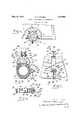
Fig. 1 is a fragmentary view ofan automobile equipped with devices embodying the invention.
V F ig. 2 is an enlarged view of a portion of Fig. 1.
' Fig. 3 is a section on line 33 of Fig. 2. Fig. 4 is a sectional view of the device taken on line 4-4501 Fig. 3.
In the drawing, the device is shown as applied to a wood wheel but it is to be understood that itis applicable to wire Wheels by slight change in the arms.
Referring to the drawing, there is shown at 10 a felly, at 11 a felly rim, at 12 Va de- .mountable the rim and at 13 a pneumatic tire all of which may be of any well known form of construction. The spokes are shown The preferredform of non-skid device embodying the invention is as follows:
Two clamping members A, B preferably of metal, are adjustably connected together and have arms 15, 16 respectively which serve as jaws to embrace the wheel rim and tire rim. The arms 15, 16 have cut out spaces to form respectively cross-over portions 17, 18 which lie. side by side and extend in opposite directions.
The cross-over portion 17 of the arm 15 merges into an outwardly bowed portion 19 terminating in an upwardly extending straight portion 21 as viewed in Fig. 3 and the cross-over portion 18 merges into a bowed portion 20 terminating in a straight portion are provided "which passes a headed bolt 23 having on its th a m action is permitted to cause the extends further 22 The said portions 21 and 22 respectively with aligned holes through outer end a nut 24. By setting up the nut 24 thea'rms'l5 16 will be drawn toward each other and cause the arms 15-, 16 to tighten their grip" on the tire rim and by turning the nut in the. reverse direction it permits spreadmg the armsito. -loosen their grip on the tire IlIII. The bolt hole in thearm extension 21 and the portion of the bolt which engages therein are preferably non-circular so that the bolt will not turn on its axis. be clearly pointed out and defined in the A'bolt 25 passes through a screw hole in the bowed portion 20 and has a ball and socketconnection at 26 with a foot piece 27. The
A screw 33 passes through a hole in abearing block 34 and at its lower end is screwed into the prong head 30. The block 34 is adjustably mounted in the grooved ways 29. The screw 33 has a head 35 which engages the upper end of the block 34L to limit the down" ward movement of the head 30 and theblades '31 and 32. A coil spring 36 around the screw 33 is under compression and its opposite ends engage-respectively the upper end of the head 30 and thelower end of the block 34: to normally cause the blades 31, 32
to extend slightly below the plane of the surface on which the tire travels. The spring will permit the iblades t'o yield when riding over anjuneven surface. s.
as shown, any other suitable'pointed members may be employed. For convenience I have designated them generally. as prong members.
Preferably means are provided whereby the prong members may be retained at an elevation above the surface on'which the car is travelling during weather when the device is notneeded for non-skid purposes. To this end'the block 34: is secured to the'blocks 37, 37 which are adjustable longitudinally of the arm 28; Theblocks 37,37 have flanges 3 8 -between which the "block 34 is secured by a screw 39.
' The blocks 37 are adjustablelongitudinally of the extension arm 28. To'this end the outer sides of the arm 28 are formed with transverse teeth 4O and the innerfaces of the two blocks 37 are formed with teeth 41 adapted to engage in the'gro'oves between the teeth 40. looseningthe-screw the blocks 37, 37 jmay be moved furtherapart' to permit disengagement of their teeth from the teeth 40 of the arm 28 and thus permit readjustment of theblocks 37 "upwardly and raise the blades 31, 32. Then the's'crew 39 may beset 'up again to secure the blocksf37 in the raised position;
When adjusted to operative position for icy' weather or whenever otherwise the ground is slippery, it is preferable to have the blades normally'extend about one-half of an inch below the periphery ofthe tire, but this distance may be varied according to the desire of the user.
' When the device is adjusted so that the blades .will' normally {extend down low enough to be operative as a'non-skid, the
sprin 36 W l d- Whl e e e 'e adjustably secured together at their upper .ends to permit the lower portions to be moved into and out of gripping engagement wlth a wheel rim, means for clamping the said arms to a wheel mm, a prong member,
' one of said arms having at its lower end a ,holder for said prong member, said prong member being adjustable up and down in said holder, a spring seat for said prong member which normally causes said prong or to var'ylng positions Iof elevation on said arm.
the surface on which the vehicle travels, two arms which he crosswise of each other intermediate their ends, said arms having por-;
tions which are adapted to engage the inner face of thefelly and having portions adapted to embrace the wheel rim, means to move "bodily toward each other the end 'portions of the arms on the opposite side of the crossover from the wheel rim, and means to spread further apart the portions of'said arms which are intermediate the said arm ends and the cross-over and thereby draw the clamping portions toward each. other.
' '3. A non-skid attachment for a vehicle wheel having'a projection adapted to engage the surface on which the vehicle travels, two clamping membe'rswhich lie crosswise of each other intermediate their ends, said two clamping members having portions adapted to engage the telly and to grip the rim of the'wheel, the said two clamping members having arms which extend on the opposite side of the cross-over from the wheelr-im, a bolt which passes through the two arms near their ends, means for moving the said bolt axially whereby the said two arms can be drawn toward each other and cause the clamping membersto grip'the wheel rim, a screw bolt which passes through one of said "arms between saidcross-ov'er and said first bolt and is thereby operativev to spread the intermediate portions of said two arms further apart and cause the clamping portions to be drawn toward each other.
4. A 'non-skid attachment for a vehicle wheel having two clamping members which :lie'crosswise of each other,said two members having portions which are adapted to grip member to project below the lower end,of;-. said holder, said prong holder and the arm to which itis attached having interengaging .teeth'which permit adjustment of said hold- 7 p 7 .eo 2. Anon-skid attachment for a vehicle wheel having a projectionadapted to engage the rim of a wheel, the clamping members having arms which are adapted to extend from the cross-over toward the axis of the wheel, a bolt which passes through said arms near their ends and is adapted to be operated to draw said arms and clamping members toward each other to cause the clamping members to grip the wheel rim, said arms being formed intermediate their ends with a portion having a concave inner face, a bolt which passes through one of said concave portions and presses against the concaved portion of the other arm and is operative to spread said arms further apart intermediate their ends and cause the clamping members to grip the wheel rim, one of said clamping members having a skid preventing member which projects below the tread surface of the wheel.
5. A non-skid attachment for a vehicle wheel having two clamping members which lie crosswise of each other, said two members having portions which are adapted to grip the rim of a wheel, the clamping members having arms which are adapted to extend from the cross-over toward the axis of the wheel, a bolt which passes through said arms near their ends and is adapted to be operated to draw said arms and clamping members toward each other to cause the clamping members to grip the wheel rim, said arms being formed intermediate their ends with a concave inner face, a bolt which passes through one of said concave faced portions and has a socket connection with a foot piece having a convex face which presses against the concave surface of the other arm and is operative to spread said arms further apart intermediate their ends and cause the clamping members to grip the wheel rim, one of said clamping members having a skid preventing members which projects below the tread surface of the wheel.
In testimony whereof I afi ix my signature.
MARTIN F. CONNELL.
Priority Applications (1)
| Application Number | Priority Date | Filing Date | Title |
|---|---|---|---|
| US568020A US1908692A (en) | 1931-10-10 | 1931-10-10 | Nonskid attachment for automobiles |
Applications Claiming Priority (1)
| Application Number | Priority Date | Filing Date | Title |
|---|---|---|---|
| US568020A US1908692A (en) | 1931-10-10 | 1931-10-10 | Nonskid attachment for automobiles |
Publications (1)
| Publication Number | Publication Date |
|---|---|
| US1908692A true US1908692A (en) | 1933-05-16 |
Family
ID=24269593
Family Applications (1)
| Application Number | Title | Priority Date | Filing Date |
|---|---|---|---|
| US568020A Expired - Lifetime US1908692A (en) | 1931-10-10 | 1931-10-10 | Nonskid attachment for automobiles |
Country Status (1)
| Country | Link |
|---|---|
| US (1) | US1908692A (en) |
Cited By (4)
| Publication number | Priority date | Publication date | Assignee | Title |
|---|---|---|---|---|
| US3382008A (en) * | 1966-07-19 | 1968-05-07 | Edward J. Kindlon | Adjustable tread traction device |
| US4252377A (en) * | 1978-04-05 | 1981-02-24 | Carter Bros. Iron Works, Inc. | Blowout protector |
| US4266832A (en) * | 1978-03-06 | 1981-05-12 | Michel Boyer | Vehicle wheel anti-slip device |
| US4685743A (en) * | 1984-12-15 | 1987-08-11 | Hitoshi Sakurai | Wheel anti-skid attachment |
-
1931
- 1931-10-10 US US568020A patent/US1908692A/en not_active Expired - Lifetime
Cited By (4)
| Publication number | Priority date | Publication date | Assignee | Title |
|---|---|---|---|---|
| US3382008A (en) * | 1966-07-19 | 1968-05-07 | Edward J. Kindlon | Adjustable tread traction device |
| US4266832A (en) * | 1978-03-06 | 1981-05-12 | Michel Boyer | Vehicle wheel anti-slip device |
| US4252377A (en) * | 1978-04-05 | 1981-02-24 | Carter Bros. Iron Works, Inc. | Blowout protector |
| US4685743A (en) * | 1984-12-15 | 1987-08-11 | Hitoshi Sakurai | Wheel anti-skid attachment |
Similar Documents
| Publication | Publication Date | Title |
|---|---|---|
| US2443319A (en) | Traction device | |
| DE2250955A1 (en) | SKID PROTECTION FOR VEHICLES | |
| US2598851A (en) | Traction device | |
| US1908692A (en) | Nonskid attachment for automobiles | |
| US4662417A (en) | Antiskid traction device | |
| US2066368A (en) | Antiskid device | |
| US1366031A (en) | Traction-block for automobiles | |
| US2044812A (en) | Antiskidding device for automobiles | |
| US1213949A (en) | Antiskidding grip-tread for vehicle-wheels. | |
| US1370758A (en) | Antiskid device for wheel-tires | |
| US3482880A (en) | Device for improving the traction,stability and flotation of vehicles with tired wheels | |
| US1400358A (en) | Antiskid device | |
| CN216545568U (en) | Special antiskid tire for snowfield | |
| US3178232A (en) | Non-skid and non-slide attachment for vehicle wheels | |
| US1215302A (en) | Non-skid device. | |
| US1800878A (en) | Traction device for vehicle tires | |
| US2681680A (en) | Nonskid tire | |
| US2457068A (en) | Antiskid chain | |
| US1359887A (en) | Mud-shoe | |
| US1655122A (en) | Antiskid tire chain | |
| US1257379A (en) | Tread-shoe for vehicle-wheels. | |
| US1695450A (en) | Tire shoe | |
| US1441198A (en) | Mud lug | |
| US1662392A (en) | Traction device for motor vehicles | |
| US1522816A (en) | Runner attachment for automobiles |