US1908642A - Die - Google Patents
Die Download PDFInfo
- Publication number
- US1908642A US1908642A US366364A US36636429A US1908642A US 1908642 A US1908642 A US 1908642A US 366364 A US366364 A US 366364A US 36636429 A US36636429 A US 36636429A US 1908642 A US1908642 A US 1908642A
- Authority
- US
- United States
- Prior art keywords
- die
- plate
- cutting
- block
- base
- Prior art date
- Legal status (The legal status is an assumption and is not a legal conclusion. Google has not performed a legal analysis and makes no representation as to the accuracy of the status listed.)
- Expired - Lifetime
Links
Images


Classifications
-
- C—CHEMISTRY; METALLURGY
- C14—SKINS; HIDES; PELTS; LEATHER
- C14B—MECHANICAL TREATMENT OR PROCESSING OF SKINS, HIDES OR LEATHER IN GENERAL; PELT-SHEARING MACHINES; INTESTINE-SPLITTING MACHINES
- C14B5/00—Clicking, perforating, or cutting leather
- C14B5/02—Stamps or dies for leather articles
-
- Y—GENERAL TAGGING OF NEW TECHNOLOGICAL DEVELOPMENTS; GENERAL TAGGING OF CROSS-SECTIONAL TECHNOLOGIES SPANNING OVER SEVERAL SECTIONS OF THE IPC; TECHNICAL SUBJECTS COVERED BY FORMER USPC CROSS-REFERENCE ART COLLECTIONS [XRACs] AND DIGESTS
- Y10—TECHNICAL SUBJECTS COVERED BY FORMER USPC
- Y10T—TECHNICAL SUBJECTS COVERED BY FORMER US CLASSIFICATION
- Y10T83/00—Cutting
- Y10T83/202—With product handling means
- Y10T83/2092—Means to move, guide, or permit free fall or flight of product
- Y10T83/2096—Means to move product out of contact with tool
- Y10T83/2135—Moving stripper timed with tool stroke
- Y10T83/2144—Single stripper operative upon plural tools
-
- Y—GENERAL TAGGING OF NEW TECHNOLOGICAL DEVELOPMENTS; GENERAL TAGGING OF CROSS-SECTIONAL TECHNOLOGIES SPANNING OVER SEVERAL SECTIONS OF THE IPC; TECHNICAL SUBJECTS COVERED BY FORMER USPC CROSS-REFERENCE ART COLLECTIONS [XRACs] AND DIGESTS
- Y10—TECHNICAL SUBJECTS COVERED BY FORMER USPC
- Y10T—TECHNICAL SUBJECTS COVERED BY FORMER US CLASSIFICATION
- Y10T83/00—Cutting
- Y10T83/202—With product handling means
- Y10T83/2092—Means to move, guide, or permit free fall or flight of product
- Y10T83/2096—Means to move product out of contact with tool
- Y10T83/2135—Moving stripper timed with tool stroke
- Y10T83/2163—Stripper biased against product
- Y10T83/2166—Spring biased stripper
-
- Y—GENERAL TAGGING OF NEW TECHNOLOGICAL DEVELOPMENTS; GENERAL TAGGING OF CROSS-SECTIONAL TECHNOLOGIES SPANNING OVER SEVERAL SECTIONS OF THE IPC; TECHNICAL SUBJECTS COVERED BY FORMER USPC CROSS-REFERENCE ART COLLECTIONS [XRACs] AND DIGESTS
- Y10—TECHNICAL SUBJECTS COVERED BY FORMER USPC
- Y10T—TECHNICAL SUBJECTS COVERED BY FORMER US CLASSIFICATION
- Y10T83/00—Cutting
- Y10T83/869—Means to drive or to guide tool
- Y10T83/8752—Tool moves work to and against cooperating tool
- Y10T83/8753—With means to clamp or bind work to moving tool
-
- Y—GENERAL TAGGING OF NEW TECHNOLOGICAL DEVELOPMENTS; GENERAL TAGGING OF CROSS-SECTIONAL TECHNOLOGIES SPANNING OVER SEVERAL SECTIONS OF THE IPC; TECHNICAL SUBJECTS COVERED BY FORMER USPC CROSS-REFERENCE ART COLLECTIONS [XRACs] AND DIGESTS
- Y10—TECHNICAL SUBJECTS COVERED BY FORMER USPC
- Y10T—TECHNICAL SUBJECTS COVERED BY FORMER US CLASSIFICATION
- Y10T83/00—Cutting
- Y10T83/869—Means to drive or to guide tool
- Y10T83/8798—With simple oscillating motion only
- Y10T83/8799—Plural tool pairs
- Y10T83/8801—Plural tools on single oscillating arm [i.e., tool holder]
Definitions
- This invention relates to dies for cutting or dying out blanks from sheet material such as leather, libre-board, cloth, or the like, and pertains more particularly to dies of the type used with a cut-out press for cutting out ornamental perforations and the like in the fitted uppers of shoes, slippers, and the like, although certain features of the invention are applicable as well to dies for cutting .'10 flat work.
- a further obj ect is the provision of a die structure in which the die block and the locating gage or mask are rapidly and easily detachable from the remainder of the structure, the latter being adapted for the alternative reception of a plurality of dies and gages or masks adapted for differently cutting or ornamenting the work, thereby obviating the necessity of manufacturing a complete die structure for each different die or cutter and permitting the same base and hinge structure to be used for a plurality of different designs.
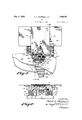
- Figure 1 is a. plan view of one illustrative embodiment of the invention, sho vving apiece of work in position in the die; 1
- a 5 V Figure 2 is a front elevation of the same
- Figure 3 is a plan vienT of the die structure as it appears with the die block and locating plate removed;
- Figure t is a rear elevation of the structure of Figure 3 ;V
- Figure 5 is a vertical sectional view taken on the irregular line .5*5 in Figure 1, the work being indicated by broken-and-dotted lines;
- Figure 6 is a plan view of the die block of Figure l as it appears when detached;
- FIG. 7 is a fragmentary sectional view taken on the line 7 7 in Figure 3;
- Figure 8 is a vertical front-to-rcar sec- 60 tional view of a modification
- Figure 9 is a plan view of the same, parts of the gage being broken away, and
- Figure 10 is a front elevation of the same.
- rlhe embodiment shown in Figures 1 to G5 7, inclusive comprises a base or master die holderV 1, a die block 2, a stripper 3, and a locating device l to facilitate the positioning of the stecken the die.
- the base 1 is a substantially rectangular slab of metal bifurcated or recessed at its rear end to form a pair of arms 5 that straddle a portion ofthe cut-out press therebetween.
- rlhe -die block 2 is supported on and spaced from the base 1 by columns 6, preferably of cylindrical 75 formation. The ends of two, at least, of the columns 6 are reduced in diameter to form shoulders 7.
- the reduced ends 8 may be provided with tapped holes 11 to receive screws 12 that pass through the blocks l 85 and 2, respectively, to detachably secure said blocks in spaced relation to one another.
- the reduced ends fit snugly, as indicated, so that the use of screws may be dispensed with to facilitate interchange of dies.
- Apertures 9 are preferably counterbored at their lower ends 14 to receive the heads of screws 12.
- the base plate 1 is preferably provided with a large number of apertures 9, closely spaced and regularly distributed over a wide area for alternative co-operation with said spacers whereby a cutting unit 2 may be secured to the base 1 in any one of a plurality of alternative positions thereon or whereby the spacers may be separated or brought together to accommodate cutting locks of dierent areas and positions.
- the apertures 9 constitute but one form of alternative conformations that may co-operate with any suitable form of complemental conformations of which the complemental ends 8 of the spacers are merely illustrative.
- the die block 2 presents elevated portions 15 on its upper face that operate on the stock or work.
- the portions 15 terminate upwardly in cutting edges 16 that are adapted to form ornamental perforations in the stock, the scrap passing down through the openings 17 that extend through the block and are defined by the cutting edges 16.
- the assembling of the cutting unit 2 on the base 1 may be facilitated by suitably marking the apertures 9 for individual identification,
- the stripper 3 preferably comprises a thin plate or metal sheet, having riveted or otherwise suitably secured thereto the depending studs 20, that fit slidably in openings 21 in the block 2.
- the openings 21 enlarge at their upper ends to form sockets 22 for receiving the compressed expansible springs 23 that are coiled loosely around the studs 2O and bear against the underside of the stripper plate 3.
- the lower ends of Astuds 20 are provided with tapped holes to receive screws 24 whose heads 25 are adapted to abut against the underside of the block 2 and thereby to limit the ascent of the plate 3 under the impulsion of the springs 23.
- Plate 3 is provided with openings 26 to accommodate the portions 15 when the plate descends, and with openings 27 to afford access to the spacer screws 12 in the die'block 2.
- the stripper plate 3 projects forwardly of the die 2 to form a work supporting tongue 28 adapted to be embraced by the fitted upper of a shoe.
- the rear ends of the arms 5 are provided with screw-threaded openings therethrough to receive the externally screw-threaded lower ends 29 of sleeves 30, that are provided with intermediate annular flanges 31 that present shoulders 32 and 33 that are adapted to react respectively against the upper face of the base 1 and the lower ends of the coinpressed expansible springs 34, loosely coiled around the sleeves 30.
- rl ⁇ he lower end of each of the sleeves 30 is larger in internal diameter than the upper end of the sleeves in order to leave a shoulder 35, that is adapted to be engaged by the head 36 of a screw 37, screwed into a tapped hole in the 'lower end of the stud 38, that fits slidably in the upper end of the sleeves 30.
- each stud 38 enlarges to form a shoulder 39 against which the upper end of the spring 34 may be seated, thereby urging stud 38 upwardly until head 36 of screw 37 abuts against shoulder 35.
- the upper ends of the lstudsV 38 are bifurcated to receive between prongs 40 the tongues 41 of the studs 42, whose upper ends 43 are riveted or otherwise suitably secured to the locating plate 44.
- Tongues 41 and prongs 40 are pivotally connected by a pin 45, that passes through the prongs and tongues of each pair of studs 38 and 42.
- Pin 45 is preferably held against longitudinal displacement by means of nuts or knobs 46, that lit the externally screwthreaded ends 47 of the pin 45.
- An inverted U-shaped member 48 has its extremities 49 attached to the rear ends of the straddling portions 5 of the base 1 by means of screws 59, the intermediate portion 51 of said member being adapted to pass over the aforesaid stationary post of the press and to trip a safety device thereon.
- the portion 51 is provided with a pair of vertically extending apertures or sockets 52 that enlarge at their lower ends to form shoulders 53 and to vreceive the head of screws 54 that are adapted to abut against the shoulders 53. Screws 54 screw tightly into tapped holes in the lower ends of rods 55, slidably fitting in apertures 52.
- Compressed eXpansible coil springs 56 surround the rods and bear against the underside of plate 44 and the upper face of the horizontal portion 51 of member48, tending to rotate plate 44 in a clockwise direction about pivot rod 45, as seen in Figure 5.
- Rods 55 are preferably provided with conformations or heads 57 at their upper ends that engage the springs 56 between adjacent convolutions toprevent withdrawal of the rods 55 down through the holes 52.
- the work locating plate or gage 4 is secured upon the upper face of the plate 44 by a screw 58that screws into a tapped hole 59 in plate 44 and whose head bears against the bottom of a vrecess 60 in plate 4.
- Plate 4 Vis prevented from rotating about screw 58 by a pair of dowel pins 61, that are riveted to the plate 4 and t into openings 62 therefor in the plate 41. rllhe forward end of plate 4 presents edges 63 that conform to or follow locating marks or identifying characters, such as the edges 64 on the fitted upper 65 of a shoe, and that serve thereby to locate the litted upper correctly with relation to the die.
- the construction of the die having been fully described, the manner of using it will be readily understood.
- the base 1 of the die fits Aslidably in the groove of the table or bed of the press so that it may be with'- drawn from under the head of the press to a position in front of the operator.
- the operator rotates plate 44 counter-clockwise against the urge of springs 56 and thereby lifts plate 4 lfrom its normal position of abutment against stripper plate 3 to the position shown in broken lines in Figure 5, and, having placed the sleeve-like fitted upper 65 around the tongue 28 and the portion to be ornamented over the cutting edges of the die 2, the edges 64 of the upper are placed approximately under the edges 63 of the locating plate 4 and the plate 4 is permitted to descend automatically and clamp the portion of the upper forward of the said edges between the plates 3 and 4, after which the clamped upper may be shifted to bring the edges 64 of the upper into correct registry with the edges 63 of the hold down or locating plate or gage 4.
- the block 2 overhangs the spacers 6 so that the upper can be eX- tended underneath as well as above the block 2 and that a substantial space is provided between the rear end of the block'2 and the posts 38 to which the plate 44 is pivoted. It will be observed that this space also eX- tends under the die block 2 and between the posts 38 and that it is sufficiently deep to receive a substantial portion of a. made or assembled upper that may need to be extended thereinto when certain portions of the upper are placed against the cutting edges.
- the said space or recess is also preferably sufficiently deep to receive the hand of the operator, or so much of it as is necessary for adjusting the upper in relation to the die.
- the looped upper is passed directly rearwardly over the forwardly projecting work supporting tongue 28 of the stripper plate 3 in order to place the work in position on the die. It is also worthy of note that after the work has been placed on the die, it may be held thereonl automatically by the holddown gage 4, thereby making it unnecessary for the operator to hold the gage against the work while it is Asubsequently being shifted rearwardly from the work placing position on the machine to the work cutting position thereon.
- the gage has been for pumps and to have-a strap portion 66 that is passed rearwardly underneath the gage 4 beyond thel stripper platev 3.
- the lining 67 of the upper is intentionally cut so as to allow a portion 68 to project beyond -the top seam 64 of the upper so that it may be clamped between the gage 4 and stripper V3, and after the projecting portion 68 of the 'lining has served its purpose in thus affording a clamping site on the upper, it may be cut oif at the top seam 64.
- the spacers or supports 6 are placed at strategic points underneath the die under the cutting edges or so that they lie in the line of pressure exerted on the die by the vhead of the press, thereby eliminating undue bending or shearing strains that might occur in the die if it were supported at points Outside of such line of pressure. Moreover, less material need be used than is required in cases where the die must be supported at an extended marginal portion on spacers or lugs located definitely and non-shiftably on the base plate. Further, the spacers 6 are of small dimensions and located so as not to obstruct the discharge of the scrap from the openings 17, and the scrap can be easily removed from the openwork supporting arrangement produced by the posts 6.
- the pin 45 insures the correctV alinement of the pivotal axis of each hinge post with that of the other, and the pin may be easily. removed to detach plate 44 from the die by unscrewing the nuts 46.
- Figures 8, 9, and 10 exhibit a modification of the form of the invention shown in Figf ures 1 to 7, inclusive.
- the spacers 69 are tubular, and are secured to the base 1 and die block 7 0 by screws 71 that screw into tapped holes in the block 70.
- the cutting edges of the cutting unit 70 are arranged symmetrically with respect to the front-to-rear medial axis of the die, so that the single die presents right and left cutting designs on opposite sides of such axis, whereby it is capable of cutting the reversely shaped perforations of both sides of the upper, thereby avoiding the expense of two separate dies, one side first of the shoe upper being held between the locating ⁇ plate 72 and one of the tongues 7 3 of the stripper plate 74 and being cut by the forming means 15 Vadjacent to the said tongue, after which the other side of the shoe is held against the other tongue 7 5 and cut by the reversely shaped forming means 15 associated therewith.
- the locating gage 72 covers the entire stripper plate 74 and its tongues 7 3 and 75, as well as .the space 76 between said tongues, thereby enabling the operator to lift the gage 72 very conveniently by grasping it between the tongues 7 3 and 7 5.
- Plate 72 contains perforations 77 that conform in outline to stitches or other identifying characters on the fitted upper 78, and that serve thereby to locate the latter correctly with relation to the cutting edges 16 of the die.
- Plate 72 also, vcontains openings 79 that are adapted to register with similar openings 8O in plate 74 to indicate the correct positioning of these plates vwith relation to one another.
- the plate 72 When the upper has been so placed, the plate 72 is lowered, and the upper or blank 78 is shifted until the appropriate locating characters thereon, such, for instance, as a line of stitching or the edge of an overlaid portion follow and then pushes the die under the head of the press, whereupon-the head descends on the plate 72, pressing the-blank or upper against the cutting edges 16 and against the stripper plate 74, which thereupon descends until the upper has been died-out, the scrap descending through the openings in the die that are defined by the edges 16.
- the appropriate locating characters thereon such, for instance, as a line of stitching or the edge of an overlaid portion follow and then pushes the die under the head of the press, whereupon-the head descends on the plate 72, pressing the-blank or upper against the cutting edges 16 and against the stripper plate 74, which thereupon descends until the upper has been died-out, the scrap descending through the openings in the die that are defined by the edges 16.
- a baseblock In a die of the character described, a baseblock, a cutting b lock, spacers connecting said base and cutting blocks and being internally screw-threaded in each end, screws passing in unthreaded relation through said blocks and screwing into the screw-threaded ends of said spacers, and a stripperfor the cutting block having openings therein overlying said screws to afford access thereto.
- a master die holder having a pivoted gage-holding member mounted there ⁇ on, a gage removably connected therewith,
- said member having confor-mations adapted vto cooperate with conformations on the gage to secure the latter in proper position on said member.
- a masl ter die holder having a plurality of predetermined mounting means associated therewith for kselective use, and means for detachably supporting different die. blocks on said holder in association with selective groups of the plurality Vof predetermined mounting means, thereby to accommodate variable thrust conditions arising by the substitution of one die for another.
- a base support a cutting unit mounted thereon, and a plurality of spacers supporting different points of said cutting unit, said base having a plurality of differently located contormations for selective cooperation with said spacers whereby different cutting units may be mounted on said base in dierent selected, predetermined positions thereon.
- a base supporting member having a. plurality or" closely spaced apertures therein distributed over a wide area for selective use and means for locating different cutting units, selectively in predetermined groups of said apertures.
- a die for the purpose set forth comprising a supporting base portion, a cutting die block disposed thereover in spaced relation thereto and apertured for the discharge of scrap underneath itself, and spacing and supporting means connecting the base and cutting block in the area of pressure exerted on the latter and so as to permit the discharge of scrap through said cutting block, said spacing means comprising columns being detachably seated in said base portion and freely supporting said die block, and means for selectively seating said columns in variable posit-ion in said base, whereby to accommodate variable thrust conditions arising by the substitution of one die for another.
- a master die holder for a shoe ornamenting die block and means for detachably connecting different blocks to said holder' in different positions, said holder provided with selective means to retain said connecting means in said different selected positions, thereby to accommodate variable thrust conditions arising by the substitution of one die for another.
- a master die holder for a shoe ornamenting die block a pivoted gauge holding member mounted thereon, a gauge removably connected therewith, said member having conformations adapted to cooperate with conformations cn the gauge to secure the latter in proper position on the member, and means for detachably connecting different blocks to said holder in dierent positions, said holder being provided with selective means to retain said connecting means in diierent selected positions, thereby to accommodate variable CHARLES A. MESSMER, JR.
Landscapes
- Engineering & Computer Science (AREA)
- Mechanical Engineering (AREA)
- Chemical & Material Sciences (AREA)
- Organic Chemistry (AREA)
- Footwear And Its Accessory, Manufacturing Method And Apparatuses (AREA)
Description
May 9, 1933 c. A. MEssMER, JR 1,908,642
DIE
Filed May 27, 1929 4 Sheets-Sheet 1 May 9, 1933.
c. A. MESSMER, .JR 31,998,642
DIE
Filed May 27, 1929 4 sheets-sheet Patented May 9, i933 muren i stares hadnt-i2 CHARLES A. MESSMER, JR., F ST. LOUIS, MISSGURI, ASSIGNOR TO BENJAMN W. FREEMAN, OF CINCINNATI, OI-IO DIE Application led May 27,
This invention relates to dies for cutting or dying out blanks from sheet material such as leather, libre-board, cloth, or the like, and pertains more particularly to dies of the type used with a cut-out press for cutting out ornamental perforations and the like in the fitted uppers of shoes, slippers, and the like, although certain features of the invention are applicable as well to dies for cutting .'10 flat work.
f tions.
A further obj ect is the provision of a die structure in which the die block and the locating gage or mask are rapidly and easily detachable from the remainder of the structure, the latter being adapted for the alternative reception of a plurality of dies and gages or masks adapted for differently cutting or ornamenting the work, thereby obviating the necessity of manufacturing a complete die structure for each different die or cutter and permitting the same base and hinge structure to be used for a plurality of different designs.
Other objects, advantages, and desirable features of the invention will appear in the course of the fallowing description of illustrative embodiments of the invention.
In the accompanying drawings forming part of this specification, in which like-numto bers of reference denote like parts wherever they occur,
Figure 1 is a. plan view of one illustrative embodiment of the invention, sho vving apiece of work in position in the die; 1
A 5 VFigure 2 is a front elevation of the same,
1929. Serial No. 366,364.
indicating the work by means of broken lines; Figure 3 is a plan vienT of the die structure as it appears with the die block and locating plate removed;
Figure t is a rear elevation of the structure of Figure 3 ;V
Figure 5 is a vertical sectional view taken on the irregular line .5*5 in Figure 1, the work being indicated by broken-and-dotted lines;
Figure 6 is a plan view of the die block of Figure l as it appears when detached;
Figure 7 is a fragmentary sectional view taken on the line 7 7 in Figure 3; I
Figure 8 is a vertical front-to-rcar sec- 60 tional view of a modification; Y,
Figure 9 is a plan view of the same, parts of the gage being broken away, and
Figure 10 is a front elevation of the same. rlhe embodiment shown in Figures 1 to G5 7, inclusive, comprises a base or master die holderV 1, a die block 2, a stripper 3, and a locating device l to facilitate the positioning of the stecken the die. The base 1 is a substantially rectangular slab of metal bifurcated or recessed at its rear end to form a pair of arms 5 that straddle a portion ofthe cut-out press therebetween. rlhe -die block 2 is supported on and spaced from the base 1 by columns 6, preferably of cylindrical 75 formation. The ends of two, at least, of the columns 6 are reduced in diameter to form shoulders 7. that abut against the underside of the block 2 and the upper face of the block 1, respectively, the diametrically reduced end portions 8 entering apertures 9 in the base l and apertures l0 in the die block 2, respectively. The reduced ends 8 may be provided with tapped holes 11 to receive screws 12 that pass through the blocks l 85 and 2, respectively, to detachably secure said blocks in spaced relation to one another. The reduced ends fit snugly, as indicated, so that the use of screws may be dispensed with to facilitate interchange of dies. There are preferably three such spacers 6 interposed between the blocks in order to afford a threepoint support for the die block 2. However, only two such spacers need be secured to the die block 2, the third having no reduced upper end 8, but merely an end face that underlies the block 2 to support the latter, as best shown in Figures 3 and 4. Apertures 9 are preferably counterbored at their lower ends 14 to receive the heads of screws 12. The base plate 1 is preferably provided with a large number of apertures 9, closely spaced and regularly distributed over a wide area for alternative co-operation with said spacers whereby a cutting unit 2 may be secured to the base 1 in any one of a plurality of alternative positions thereon or whereby the spacers may be separated or brought together to accommodate cutting locks of dierent areas and positions. It will be understood and appreciated thatthe apertures 9 constitute but one form of alternative conformations that may co-operate with any suitable form of complemental conformations of which the complemental ends 8 of the spacers are merely illustrative. The die block 2 presents elevated portions 15 on its upper face that operate on the stock or work. In the illustrative embodiments the portions 15 terminate upwardly in cutting edges 16 that are adapted to form ornamental perforations in the stock, the scrap passing down through the openings 17 that extend through the block and are defined by the cutting edges 16. The assembling of the cutting unit 2 on the base 1 may be facilitated by suitably marking the apertures 9 for individual identification,
as by means of numbers 18, and by marking those portions of the die adjacent the spacers 6 that enter certain apertures 9 with identification marks 19 that correspond to the marks 18 of the holes 9 in which the respective spacers are secured.
The stripper 3 preferably comprises a thin plate or metal sheet, having riveted or otherwise suitably secured thereto the depending studs 20, that fit slidably in openings 21 in the block 2. The openings 21 enlarge at their upper ends to form sockets 22 for receiving the compressed expansible springs 23 that are coiled loosely around the studs 2O and bear against the underside of the stripper plate 3. The lower ends of Astuds 20 are provided with tapped holes to receive screws 24 whose heads 25 are adapted to abut against the underside of the block 2 and thereby to limit the ascent of the plate 3 under the impulsion of the springs 23. Plate 3 is provided with openings 26 to accommodate the portions 15 when the plate descends, and with openings 27 to afford access to the spacer screws 12 in the die'block 2. The stripper plate 3 projects forwardly of the die 2 to form a work supporting tongue 28 adapted to be embraced by the fitted upper of a shoe.
The rear ends of the arms 5 are provided with screw-threaded openings therethrough to receive the externally screw-threaded lower ends 29 of sleeves 30, that are provided with intermediate annular flanges 31 that present shoulders 32 and 33 that are adapted to react respectively against the upper face of the base 1 and the lower ends of the coinpressed expansible springs 34, loosely coiled around the sleeves 30. rl`he lower end of each of the sleeves 30 is larger in internal diameter than the upper end of the sleeves in order to leave a shoulder 35, that is adapted to be engaged by the head 36 of a screw 37, screwed into a tapped hole in the 'lower end of the stud 38, that fits slidably in the upper end of the sleeves 30. The upper end of each stud 38 enlarges to form a shoulder 39 against which the upper end of the spring 34 may be seated, thereby urging stud 38 upwardly until head 36 of screw 37 abuts against shoulder 35. The upper ends of the lstudsV 38 are bifurcated to receive between prongs 40 the tongues 41 of the studs 42, whose upper ends 43 are riveted or otherwise suitably secured to the locating plate 44. Tongues 41 and prongs 40 are pivotally connected by a pin 45, that passes through the prongs and tongues of each pair of studs 38 and 42. Pin 45 is preferably held against longitudinal displacement by means of nuts or knobs 46, that lit the externally screwthreaded ends 47 of the pin 45. An inverted U-shaped member 48 has its extremities 49 attached to the rear ends of the straddling portions 5 of the base 1 by means of screws 59, the intermediate portion 51 of said member being adapted to pass over the aforesaid stationary post of the press and to trip a safety device thereon. The portion 51 is provided with a pair of vertically extending apertures or sockets 52 that enlarge at their lower ends to form shoulders 53 and to vreceive the head of screws 54 that are adapted to abut against the shoulders 53. Screws 54 screw tightly into tapped holes in the lower ends of rods 55, slidably fitting in apertures 52. Compressed eXpansible coil springs 56 surround the rods and bear against the underside of plate 44 and the upper face of the horizontal portion 51 of member48, tending to rotate plate 44 in a clockwise direction about pivot rod 45, as seen in Figure 5. Rods 55 are preferably provided with conformations or heads 57 at their upper ends that engage the springs 56 between adjacent convolutions toprevent withdrawal of the rods 55 down through the holes 52. The work locating plate or gage 4 is secured upon the upper face of the plate 44 by a screw 58that screws into a tapped hole 59 in plate 44 and whose head bears against the bottom of a vrecess 60 in plate 4. Plate 4 Vis prevented from rotating about screw 58 by a pair of dowel pins 61, that are riveted to the plate 4 and t into openings 62 therefor in the plate 41. rllhe forward end of plate 4 presents edges 63 that conform to or follow locating marks or identifying characters, such as the edges 64 on the fitted upper 65 of a shoe, and that serve thereby to locate the litted upper correctly with relation to the die.
The construction of the die having been fully described, the manner of using it will be readily understood. The base 1 of the die fits Aslidably in the groove of the table or bed of the press so that it may be with'- drawn from under the head of the press to a position in front of the operator. Assuming the die to be in front of the operator preparatory to placing a blank or fitted upper thereon, the operator rotates plate 44 counter-clockwise against the urge of springs 56 and thereby lifts plate 4 lfrom its normal position of abutment against stripper plate 3 to the position shown in broken lines in Figure 5, and, having placed the sleeve-like fitted upper 65 around the tongue 28 and the portion to be ornamented over the cutting edges of the die 2, the edges 64 of the upper are placed approximately under the edges 63 of the locating plate 4 and the plate 4 is permitted to descend automatically and clamp the portion of the upper forward of the said edges between the plates 3 and 4, after which the clamped upper may be shifted to bring the edges 64 of the upper into correct registry with the edges 63 of the hold down or locating plate or gage 4. It will be observed that the block 2 overhangs the spacers 6 so that the upper can be eX- tended underneath as well as above the block 2 and that a substantial space is provided between the rear end of the block'2 and the posts 38 to which the plate 44 is pivoted. It will be observed that this space also eX- tends under the die block 2 and between the posts 38 and that it is sufficiently deep to receive a substantial portion of a. made or assembled upper that may need to be extended thereinto when certain portions of the upper are placed against the cutting edges. The said space or recess is also preferably sufficiently deep to receive the hand of the operator, or so much of it as is necessary for adjusting the upper in relation to the die. The looped upper is passed directly rearwardly over the forwardly projecting work supporting tongue 28 of the stripper plate 3 in order to place the work in position on the die. It is also worthy of note that after the work has been placed on the die, it may be held thereonl automatically by the holddown gage 4, thereby making it unnecessary for the operator to hold the gage against the work while it is Asubsequently being shifted rearwardly from the work placing position on the machine to the work cutting position thereon.
In the present instance, the gage has been for pumps and to have-a strap portion 66 that is passed rearwardly underneath the gage 4 beyond thel stripper platev 3. The lining 67 of the upper is intentionally cut so as to allow a portion 68 to project beyond -the top seam 64 of the upper so that it may be clamped between the gage 4 and stripper V3, and after the projecting portion 68 of the 'lining has served its purpose in thus affording a clamping site on the upper, it may be cut oif at the top seam 64.
It willrbe observed that the spacers or supports 6 are placed at strategic points underneath the die under the cutting edges or so that they lie in the line of pressure exerted on the die by the vhead of the press, thereby eliminating undue bending or shearing strains that might occur in the die if it were supported at points Outside of such line of pressure. Moreover, less material need be used than is required in cases where the die must be supported at an extended marginal portion on spacers or lugs located definitely and non-shiftably on the base plate. Further, the spacers 6 are of small dimensions and located so as not to obstruct the discharge of the scrap from the openings 17, and the scrap can be easily removed from the openwork supporting arrangement produced by the posts 6. Since this manner of supporting the die permits the use of a small die for a given cutting or oranmenting design than heretofore, economy is effected through the use of a smaller amount of the expensive steel used in the construction of the die. Moreover, the smaller die is more easily accommodatedto the inside of a made or assembled upper than a larger die.
Attention is further directed to the fact that the plate 4 can not be distorted and shifted inadvertently forward or backward, such distortion being prevented by reason of the vertical shiftability of the hinges under the pressure of the head of the press, thereby insuring at all times the proper lateral positioning of the locating plate or gage 4 with relation to the die block 2.
The pin 45 insures the correctV alinement of the pivotal axis of each hinge post with that of the other, and the pin may be easily. removed to detach plate 44 from the die by unscrewing the nuts 46.
rlhe same base and hinge structure may be used interchangeablyv with different cutting units and gage for producing a variety of designs or cut-outs in shoe uppers, thereby saving the expense of providing separate base and hinge structures for each individual cutting unit and its associated gages, as has heretofore been the practice. Moreover, the
change from one cutting unit and associated rection necessary to suitably support the work thereon. l
Figures 8, 9, and 10 exhibit a modification of the form of the invention shown in Figf ures 1 to 7, inclusive. In this form the spacers 69 are tubular, and are secured to the base 1 and die block 7 0 by screws 71 that screw into tapped holes in the block 70. The cutting edges of the cutting unit 70 are arranged symmetrically with respect to the front-to-rear medial axis of the die, so that the single die presents right and left cutting designs on opposite sides of such axis, whereby it is capable of cutting the reversely shaped perforations of both sides of the upper, thereby avoiding the expense of two separate dies, one side first of the shoe upper being held between the locating` plate 72 and one of the tongues 7 3 of the stripper plate 74 and being cut by the forming means 15 Vadjacent to the said tongue, after which the other side of the shoe is held against the other tongue 7 5 and cut by the reversely shaped forming means 15 associated therewith. In this form of the invention the locating gage 72 covers the entire stripper plate 74 and its tongues 7 3 and 75, as well as .the space 76 between said tongues, thereby enabling the operator to lift the gage 72 very conveniently by grasping it between the tongues 7 3 and 7 5. Plate 72 contains perforations 77 that conform in outline to stitches or other identifying characters on the fitted upper 78, and that serve thereby to locate the latter correctly with relation to the cutting edges 16 of the die. Plate 72, also, vcontains openings 79 that are adapted to register with similar openings 8O in plate 74 to indicate the correct positioning of these plates vwith relation to one another. The full line representation of this modification as shown in Figure 8 indicates the omission of the springs 55 that hold the mask 72 down on the work 78 automatically. If desired, a spring or springs 81 may be coiled around the hinge rod 45', as shown in dotted lines in Figure 8, and they will bear against plate 44 and a U-shaped member 82 that is a modification of the U-shaped member 48, thereby tend ing to rotate plates 44 and 72 clockwise to clamp the work automatically between plates 72 and 74. To load the die, the operator lifts plate 72 to the position shown in Figure 8, and places the fitted upper of sleeve or loop formation around one of the anteriorly projecting tongues 73 or 75 of plate 74. When the upper has been so placed, the plate 72 is lowered, and the upper or blank 78 is shifted until the appropriate locating characters thereon, such, for instance, as a line of stitching or the edge of an overlaid portion follow and then pushes the die under the head of the press, whereupon-the head descends on the plate 72, pressing the-blank or upper against the cutting edges 16 and against the stripper plate 74, which thereupon descends until the upper has been died-out, the scrap descending through the openings in the die that are defined by the edges 16. i On the upstroke of the Y head, the stripper 74 rises under the impulsion of springs 23, and the plate 72 rises under' the impulsion ofthe springs 23 and 84, also, by reason of the eforts of the springs 81. The die is then withdrawn forwardly from its position under the head of the press and the plate 72 is lifted, and the blank or upper removed, and placed on the other side of the die to die out the opposite side of the shoe, the foregoing cycle of operations being, of course, then repeated. Y
Having thus fully described this invention, I hereby reserve the benefit of all changes in form, arrangement, order, or use of parts, as it is evident that many minor changes may be made therein without departing from the spirit of this invention or the scope of the following claims.
I claim: t
1. In a die of the character described, a baseblock, a cutting b lock, spacers connecting said base and cutting blocks and being internally screw-threaded in each end, screws passing in unthreaded relation through said blocks and screwing into the screw-threaded ends of said spacers, and a stripperfor the cutting block having openings therein overlying said screws to afford access thereto.
2. In a machine for cutting designs in shoe upper material, a master die holder having a pivoted gage-holding member mounted there` on, a gage removably connected therewith,
said member having confor-mations adapted vto cooperate with conformations on the gage to secure the latter in proper position on said member.
3. In an assembly for use in a machine for cutting designs in shoe upper material, a masl ter die holder having a plurality of predetermined mounting means associated therewith for kselective use, and means for detachably supporting different die. blocks on said holder in association with selective groups of the plurality Vof predetermined mounting means, thereby to accommodate variable thrust conditions arising by the substitution of one die for another. f
4. In adie of the character described, a-
`ilo
master die holder, work positioning means thrust conditions arising by the substitution removably supported on said holder, said of one die for another.
means shiftable toward and away from a In testimony whereof I hereunto aiiX my mounted die block, and means for detachably Signature.
supporting diderent die blocks on said holder in selective, predetermined positions thereon with respect to said work positioning means, thereby to accommodate variable thrust conditions arising by the substitution of one die tor another.
5. In a device of the character described, a base support, a cutting unit mounted thereon, and a plurality of spacers supporting different points of said cutting unit, said base having a plurality of differently located contormations for selective cooperation with said spacers whereby different cutting units may be mounted on said base in dierent selected, predetermined positions thereon.
6. In a. device of the character described, a base supporting member having a. plurality or" closely spaced apertures therein distributed over a wide area for selective use and means for locating different cutting units, selectively in predetermined groups of said apertures.
7. A die for the purpose set forth comprising a supporting base portion, a cutting die block disposed thereover in spaced relation thereto and apertured for the discharge of scrap underneath itself, and spacing and supporting means connecting the base and cutting block in the area of pressure exerted on the latter and so as to permit the discharge of scrap through said cutting block, said spacing means comprising columns being detachably seated in said base portion and freely supporting said die block, and means for selectively seating said columns in variable posit-ion in said base, whereby to accommodate variable thrust conditions arising by the substitution of one die for another.
8. In a device of the character described, a master die holder for a shoe ornamenting die block, and means for detachably connecting different blocks to said holder' in different positions, said holder provided with selective means to retain said connecting means in said different selected positions, thereby to accommodate variable thrust conditions arising by the substitution of one die for another.
9. In a device of the character described, a master die holder for a shoe ornamenting die block, a pivoted gauge holding member mounted thereon, a gauge removably connected therewith, said member having conformations adapted to cooperate with conformations cn the gauge to secure the latter in proper position on the member, and means for detachably connecting different blocks to said holder in dierent positions, said holder being provided with selective means to retain said connecting means in diierent selected positions, thereby to accommodate variable CHARLES A. MESSMER, JR.
Priority Applications (1)
| Application Number | Priority Date | Filing Date | Title |
|---|---|---|---|
| US366364A US1908642A (en) | 1929-05-27 | 1929-05-27 | Die |
Applications Claiming Priority (1)
| Application Number | Priority Date | Filing Date | Title |
|---|---|---|---|
| US366364A US1908642A (en) | 1929-05-27 | 1929-05-27 | Die |
Publications (1)
| Publication Number | Publication Date |
|---|---|
| US1908642A true US1908642A (en) | 1933-05-09 |
Family
ID=23442708
Family Applications (1)
| Application Number | Title | Priority Date | Filing Date |
|---|---|---|---|
| US366364A Expired - Lifetime US1908642A (en) | 1929-05-27 | 1929-05-27 | Die |
Country Status (1)
| Country | Link |
|---|---|
| US (1) | US1908642A (en) |
-
1929
- 1929-05-27 US US366364A patent/US1908642A/en not_active Expired - Lifetime
Similar Documents
| Publication | Publication Date | Title |
|---|---|---|
| US1908642A (en) | Die | |
| US1689633A (en) | Apparatus for manufacturing ornamented shoe uppers | |
| US3253493A (en) | Unitary punch and die assembly | |
| US2239377A (en) | Method of making shoes | |
| US2039251A (en) | Perforating die | |
| US2278542A (en) | Die | |
| US2268628A (en) | Machine for bending metal gutter hangers | |
| USRE18260E (en) | messmer | |
| US2185094A (en) | Die | |
| US2013679A (en) | Shoe part ornamenting machine | |
| US1533681A (en) | Tip-perforating machine | |
| US2071003A (en) | Marking device | |
| US2208858A (en) | Die | |
| US2175725A (en) | Die | |
| US1851667A (en) | Shoe ornamenting device | |
| US2080994A (en) | Perforating die | |
| US1912158A (en) | Embossing sheet metal | |
| US2282473A (en) | Copy character holder | |
| US1990932A (en) | Ornamenting die | |
| US2059344A (en) | Machine for operating upon sheet materials | |
| USRE20202E (en) | Cut-out machine for shoe uppers | |
| US3129623A (en) | Plural die elements surrounded by single stripper pad means with work gauge overlying stripper | |
| US2234536A (en) | Marking machine | |
| US2386102A (en) | Die | |
| US2097363A (en) | Die |