US1908477A - Control device - Google Patents
Control device Download PDFInfo
- Publication number
- US1908477A US1908477A US302371A US30237128A US1908477A US 1908477 A US1908477 A US 1908477A US 302371 A US302371 A US 302371A US 30237128 A US30237128 A US 30237128A US 1908477 A US1908477 A US 1908477A
- Authority
- US
- United States
- Prior art keywords
- plunger
- lever
- valve
- move
- levers
- Prior art date
- Legal status (The legal status is an assumption and is not a legal conclusion. Google has not performed a legal analysis and makes no representation as to the accuracy of the status listed.)
- Expired - Lifetime
Links
- 239000012530 fluid Substances 0.000 description 19
- XLYOFNOQVPJJNP-UHFFFAOYSA-N water Substances O XLYOFNOQVPJJNP-UHFFFAOYSA-N 0.000 description 14
- 239000000446 fuel Substances 0.000 description 10
- 230000004044 response Effects 0.000 description 8
- 238000005192 partition Methods 0.000 description 7
- 230000002441 reversible effect Effects 0.000 description 5
- 230000007246 mechanism Effects 0.000 description 4
- 238000012856 packing Methods 0.000 description 4
- 230000001105 regulatory effect Effects 0.000 description 4
- 230000009471 action Effects 0.000 description 3
- 238000010276 construction Methods 0.000 description 3
- 230000006835 compression Effects 0.000 description 2
- 238000007906 compression Methods 0.000 description 2
- 230000001276 controlling effect Effects 0.000 description 2
- 210000005069 ears Anatomy 0.000 description 2
- 239000007788 liquid Substances 0.000 description 2
- 229910052751 metal Inorganic materials 0.000 description 2
- 230000025508 response to water Effects 0.000 description 2
- 102000007469 Actins Human genes 0.000 description 1
- 108010085238 Actins Proteins 0.000 description 1
- HEMHJVSKTPXQMS-UHFFFAOYSA-M Sodium hydroxide Chemical compound [OH-].[Na+] HEMHJVSKTPXQMS-UHFFFAOYSA-M 0.000 description 1
- 230000008859 change Effects 0.000 description 1
- 230000008602 contraction Effects 0.000 description 1
- 239000000835 fiber Substances 0.000 description 1
- 210000004907 gland Anatomy 0.000 description 1
- 238000010438 heat treatment Methods 0.000 description 1
- QSHDDOUJBYECFT-UHFFFAOYSA-N mercury Chemical compound [Hg] QSHDDOUJBYECFT-UHFFFAOYSA-N 0.000 description 1
- 229910052753 mercury Inorganic materials 0.000 description 1
- 239000002184 metal Substances 0.000 description 1
- 230000004048 modification Effects 0.000 description 1
- 238000012986 modification Methods 0.000 description 1
- 238000007789 sealing Methods 0.000 description 1
Images


Classifications
-
- F—MECHANICAL ENGINEERING; LIGHTING; HEATING; WEAPONS; BLASTING
- F24—HEATING; RANGES; VENTILATING
- F24D—DOMESTIC- OR SPACE-HEATING SYSTEMS, e.g. CENTRAL HEATING SYSTEMS; DOMESTIC HOT-WATER SUPPLY SYSTEMS; ELEMENTS OR COMPONENTS THEREFOR
- F24D19/00—Details
- F24D19/10—Arrangement or mounting of control or safety devices
- F24D19/1006—Arrangement or mounting of control or safety devices for water heating systems
- F24D19/1009—Arrangement or mounting of control or safety devices for water heating systems for central heating
- F24D19/1015—Arrangement or mounting of control or safety devices for water heating systems for central heating using a valve or valves
- F24D19/1024—Arrangement or mounting of control or safety devices for water heating systems for central heating using a valve or valves a multiple way valve
- F24D19/1033—Arrangement or mounting of control or safety devices for water heating systems for central heating using a valve or valves a multiple way valve motor operated
Definitions
- An object of my invention is to provide a device which is operable to reciprocate a plunger of acontrol means which in the preferred embodiment is a flow control valve.
- Another object is to provide a device having regulating means operable between limits to reciprocate the plunger of a valve or the like and having means to move the plunger beyond the limit of movement of the regulating means.
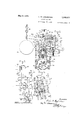
- Fig. is an end view looking from the left toward th right of Fig. 2, with the motor and gear housings removed and with the valve operable by my device in vertical central section and showing a slight modification having provision for remote control means instead of certain direct acting motor and gear control means,
- FIG. 6 is a detail view looking from the right toward the left of Fig. with a portion of the casing broken away and showing parts of the mechanism within the casing in dotted lines, and
- Fig. 7 is a diagrammatic view showing a system embodying my invention and particularly the form shown in Fig. 5.
- 1 designates generally a hollow casing comprising a support preferably composed of three sections including a mechanism housing 2, a gear housing 3, and a motor and motor housing 4:, but the casing may be formed as an integral unit.
- the mechanism housing 2 is preferably substantially rectangular having top and bottom walls 5, 6 respectively and vertical side walls 7, 8.
- the gear housing 3 is also preferably substantially rectangular having top and bottom walls 9, 10 respectively and side walls 11, 12 which respectively join the walls of the housing 2.
- Within the housing 3 is a vertical partition or wall 13 beyond-which thehousing 3 is preferably substantially cylindrical, as at 14c for union with the motor housing 4- which is preferably substantially cylindrical.
- the member 27 cooperates with a valve port 28 in a web or partition 29 which divides the interior of the casing 21 between the inlet and outlet ports 30, 31 thereof, respectively.
- Concentric with the guideway in the top of the bonnet 22 is a cylindrical recess 32 forming an annular packing receiving space around the plunger 26 containing packing 33 and into which is threaded a packing gland or nut 34 to secure the packing in the recess 32 and seal the guideway 25 around the stem 26.
- the lever member is substantially horizontal for a portion of its length, namelyfrom its fulcrum to the far side of the arm members 41, 42 and .then for the remainder of its length is inclined downward at about 18 from the horizontal.
- an internally threaded aperture 50 Through the bot tom wall 6 of housing 2 adjacent the side wall 7 and directly beneath lever member 49 is an internally threaded aperture 50 through which is threaded an adjustment screw 51 which projects into the housing and has a lock nut 52 to secure the screw 51 in adjusted position.
- the underside of lever member 49 is recessed, as at 53, to form a horizontal seat for engagement with the upwardly extending end of screw 51.
- the screw 51 serves as a stop means or abutment to limit movement of the lever member 49.
- a derice 77 Secured to the bottom wall 6 outside the housing and depending therefrom is a derice 77 comprising a substantially cup-shaped hollow casing 'Z 8 sealed along its top edge or rim to the wall 6 by screws or the like 79.
- the casing 78 is a substantially cylindrical corrugated enpa-nsible-collapsible metallic element 80 preferably a metal bellows having a head 81 closing and sealing its inner lower end which is adjacent the base of the casing '5' 8.
- the bellows 80 is hermetically sealed along its upper free edge to an annular flange projecting inwardly from the side wall of the casing T8, as at 82.
- a plunger 83 which projects upward within the bellows 80 and throu h an aperture in the bottom wall 6 uto the housing 2.
- a plunger 83 which projects upward within the bellows 80 and throu h an aperture in the bottom wall 6 uto the housing 2.
- Rigid with the side wall and extending into the housing 2 are vertical parallel spaced bearing lugs or ears 8%, which are spaced substantially equidistant from a plane transverse to walls 7, 8 and through the plunger 83.
- a tube or conduit member 96 which opens into the sealed chamber 97 formed between the casing 78 and bellows 80.
- the free end of the tube 96 is coiled or wrapped as at 98 around the end of a pilot burner 99 which is supported on a frame 100 and fed with fuel from a conduit 101 preferably tapped into the main supply line or the valve casing 21 on the inlet side 30 thereof (see Fig. 2).
- the tube 96 and chamber 9? are charged with a suitable expansible fluid so that the fluid upon'expansion due 'torthe heat of the pilot flame will compress the bellows 80 to lift plunger 83.
- the device T7 comprises athermostatic motor means which is responsive to a. characteristic of the fluid within the chamber 97 and tube 96.
- the conduit 101 may be provided with a flow control cock 102.
- the free end of the bar 146 is provided with a weight member 147 which normally acts to move the bar 146 into engagement with the pin 141 to depress the plunger 26.
- an operating means 148 preferably a chain, by which the bar 146 and weight member 147 may be held out of contact with pin 141 and by which the bar 146 may be manually or automatically OpeJated.
- the open end of housing 2 left by removal of housings 3 and 4 may be closed by a cover member 148 secured by screws or the like to housing 2.
- a safety water level means 157 is provided for the boiler which is connected by pipes and fittings 158 to the piping 151, 152 and which may be and preferably is a device such as that shown in my copending application Serial No. 120,068 filed July 2, 1926 having an overcenter float controlled arm 159 which is released when the float drops due to a drop in water level within the boiler below the safe limit.
- the boiler is also provided with motor means 160 responsive to a characteristic of the fluid in the boiler space and comprising a temperature or pressure responsive device or regulator having a pivoted operating arm 161.
- the boiler is heated by fluid fuel fed to the main burner by a pipe or conduit 162 in which is inserted the control valve 21 of my device.
- the control cock 102 is opened and the pilot burner 99 is ignited which will heat the fluid in the coil 98, expanding the same, which will collapse bellows 86 and move plunger 83 upward against the force of spring 95.
- the plunger 83 As the plunger 83 is forced upward, it will lift the lever 87 and its arm 90 out 01 Contact with the end 36 of member 36, see Fig. 2. This will release the plunger 26 and permit the spring 68 acting through lever means to lift the plunger 26 until the pin 61 strikes the underside of the lever member &9.
- valve 27 When the valve 27 has been closed by the lever 1&6 and weight member 1&7, itis held closed irrespective of the operation of the member &9. Should the lever member &9 be in down position when valve 27 is closed by weight member 1&7 and the boiler then cool so that the regulator 160 pulls up on the rod or chain 166. the rod or chain 166 and the lever member &9 will be permitted upward movement by reason of the stretching of spring 68 as lever means 55 is rotated counter clockwise of Fig. 5 about pin 61.
- the valve will be held closed by s: 1 log 75 against any operative efi'ect of the lever member &9 or spring 68 and until the device 157 manually reset and water supplied to the boiler 150.
- the device 157 may be dispensed with or placed out of operative relation by rotat ng plunger 73 untilthe arm' 73 out of engagement with member 36 irrespective of drop in Water level and the resultant functioning of device 157. If the pilot light at burner 99 should become extinguished, the expansible liquid in the tube 96 and chamber 97 will contract permitting the spring 95 to actto force arm 90 down upon member 36 to seat valve 2?
- valve 2. will be held closed by arm 90 until the pilot burner is again ignited and irrespective of operation of member 49.
- thermostat 164 which is controlled by thermostat 164.
- the motor shaft 10% will drive gear train 103 and rotate pin 131 clockwise of Figs. 3 and 4- about shaft 116 into engagement with end 36 of member 36 thus moving plunger 26 downward to seat valve 27.
- Pin 131 will engage end 36 irrespective of the position in which the valve 27 and member 36 have been placed bythe lever member 19 and should the valve be open, will force the same to its seat closing port 28.
- thermosta 164 Upon a drop in temperature in the tank 156, the thermosta 164; will call for heat and close the motor switch'means reversing the motor 1 to drive the gear train 103 to rotate pin 131 counterclockwise to the position of Figs. 3 and 4, thus permitting the valve to be opened by spring 68 until pin 61 engages member 49.
- spring means 126 will resist the clockwise swing of member 122 on its pivot 123 and cushion the engagement of pin 131 and member 122 thus stopping the motor 4-.
- the pin 131 may be manually moved out of contact with the end 36 of member 36 so that the valve 27 may be opened or to permit operation of the valve by regulator 160 by grasping the knob 13'? and pulling shaft .136 outward. This will move abutment 138 into engagement with pin 140 and rotate gear wheel 11'? counterclockwise of and to the position of Figs. 3 and 4.
- a support having a plunger mounted thereon for reciprocation, control means operable by said plunger, a pair of levers having fulcrum supports, and means to cause movement of one of said levers upon movement of the other of said levers, said one lever having operative en agement with said plunger wh :eby movement of said other lever will operate said control means, said other lever being operable to operate said control means independently of said one lever.
- a support having a plunger mounted thereon for reciprocation, control.
- said first-named lever hatdng operative engagement with'said plunger to operate said control means in the opposite direction.
- a support having plunger mounted thereon tor reciprocation, control means operable by said plunger, a lever fulcrumed on said sup port, lever n eons tulcrumed on said l ver and having operative engagement w.
- control means operable by said plunger
- said second-named means normally acting to move said plunger in the opposite direction, and means to limit movement of said other lever by said second-named means.
- a support having a plunger mounted thereon for reciprocation, control means operable by said plunger, a pair of levers having fulcrum supports, one of said levers having operative engagement with said plunger to reciprocate the same, means to cause movement of said one lever upon movement of the other of said levers, means responsive to variation in a characteristic of a fluid and having operative connection with said other lever whereby said plunger is moved in response to variation in a characteristic of said fluid, means to limit movement of said plunger by said other lever in one direction, and means operable on said plunger to move said plung er in said one direction when said other lever has reached its limit of movement.
- a support having a plunger mounted thereon for reciprocation, a pair of levers having fulcrum supports, a valve movable to open and closed positions by said plunger, one of said levers having operative connection with said plunger, means operatively connected to said one lever to cause movement thereof upon movement of the other of said levers, said means normally acting to move said valve to closed position, stop means to limit movement of said other lever to prevent said first-named means from moving said valve towards closed position beyond a predetermined degree, and means operable to move said valve to closed position when said other lever is in engagement with said stop means.
- a support having a plunger mounted thereon mounted thereon for reciprocation, a pair of levers having fulcrum supports, a valve movable to open and closed positions by said plunger, one of said levers having operative connection with said plunger, resilient means operatively connected to said one lever to cause movement thereof upon movement of the other of said levers, said resilient means normally acting to move said valve to closed position, adjustable stop-means to limit movement of said other lever to prevent said resilient means from moving said valve toward closed position beyond a predetermined degree, and thermostatic means operable to move said valve to closed position when said other lever is in engagement with said stop means.
- a support having a plunger mounted thereon for reciprocation, a valve operable by said. plunger, motor means to reciprocate said plunger, means to limit the extent to which said first-named means can move said plunger, thern'iostatically actuated means operable to move said plunger beyond the limit of movement of said plunger by said first-named means, and thermostatic means to render said motor means operable.
- a support a valve casing carried by said support, a valve in said casing, a plunger connected to said valve and reciprocably mounted on said support, a'pair of levers, one of said levers being connected to said plunger to reciprocate the same to open and close said valve, spring means acting upon said one 1"" Law lever to cause movement thereof upon movement of the other of said levers, said spring means normally urging said valve toward closed position and means to move said valve toward closed position irrespective of the operation of said other lever.
- a support a plunger mounted on said support for reciprocation and operatively connected to a valve to open and close the same, a lever fulcrumed on said support, a second lever fulcrumed on said first-named lever, a pin member carried by said plunger and extending transversely thereto, spring means nor mally urging said second-namedlever into engagement with said pin member, said spring means acting through said second-named lever and said pin member upon said first named lever to move said valve toward closed position, means to move said first-named lever in opposition to said spring means whereby said spring means acts through said secondnamed lever to open said valve.
- a support for reciprocation and operatively connected I to valve to open and close the same, a lever fulcrumed on said support, a second lever fulcrumed on said first named lever, and having a pin and slot engagement with said plunger, stop means to limit movement of said second said first named lever in opposition to said spring means whereby said spring means acts through said second named lever to open said valve, and means to move said valve beyond the limit of closing movement of said valve 1 by said first named lever and in opposition to said spring means.
- a support a valve carried by said support, a plunger mounted on said support for reciprocai ion and connected to said valve to move the same to open and closed positions, a pair 7' last-named means being manually movable to release sald valve for operation by said other lever.
- An apparatus of the character described comprising a regulatable means operable to control flow of fuel to a burner, means responsive to a variation in the characteristic of a fluid and'having permanent operative connection with said first-named means for regulating said first-namedmeans, means to limit regulation of said first-named means by said responsive means, and means acting through the operative connection to render said responsive means ineffective to control flow of fuel to the burner.
- a control means a plunger for operating said means, a lever having a fulcrum support and operably connected to said plunger to move the same in one direction, and a second lever having a fulcrum support and having operable engagement with said plunger to move the same in the opposite direction, said second-named lever having operative engagement with said first-named lever to impart the movement of said firstnamed lever to said plunger to move the said plunger in the said opposite direction.
- a control means a lever operably ensigned my name.
Landscapes
- Engineering & Computer Science (AREA)
- Physics & Mathematics (AREA)
- Thermal Sciences (AREA)
- Chemical & Material Sciences (AREA)
- Combustion & Propulsion (AREA)
- Mechanical Engineering (AREA)
- General Engineering & Computer Science (AREA)
- Mechanically-Actuated Valves (AREA)
Description
y 1933- L. w. EGGLESTON 1,908,477
CONTROL DEVICE Filed Aug. 27, 1928 3 Sheets-Sheet 1 Fig. 7 46 47 49 9 1/ f as 15 4Q M if. @425 y 9, 1933- L. w. EGGLESTON 1,908,477
CONTROL DEVICE Filed Aug. 27,1928 5 Sheets-Sheet 2 Fi .3. 1% i v1 y 1933. L. w. EGGLESTON 1,908,477
CONTROL DEVI CE Filed Aug. 27, 1928 3 Sheets-Sheet 3 avwemtoz Patented May 9, 1933 narrate era LEWIEl V]. EGGLESTON, F DETROIT, IJEEGEIGAIT, ASSTLGETOR T0 AMERICAN RADIATOR CGMPATIY, 0F ITEW' YDRK, N. Y., A CGEPORAEIGN OF NE'W JERSEY 001x? TIP-.031 DEVICE My invention relates to new and useful improvements in control devices, and more particularly to a device operable to regulate and control opening and closing movement of a valve or the like.
An object of my invention is to provide a device which is operable to reciprocate a plunger of acontrol means which in the preferred embodiment is a flow control valve.
Another object is to provide a device having regulating means operable between limits to reciprocate the plunger of a valve or the like and having means to move the plunger beyond the limit of movement of the regulating means.
Other objects of the invention will be apparent from the detailed description and operation of the device and from the appended claims.
The invention consists in the improved construction and combination of parts and their aggroupment in operative relation to be more fully described hereinafter and the novelty of which will be particularly pointed out and distinctly claimed.
In the accompanying drawings, to be taken as a part of this specification, I have fully and clearly illustrated a preferred embodiment of my invention, in which drawings Figure 1 is a top plan view of the device embodying my invention,
Fig. 2 is a side view in partial vertical section, and showing certain pilot burner means and having parts of the casing broken away to show the internal construction of my device;
Fig. 3 is an end view with the end cover member removed and looking from the right toward the left of Fig. 2;
4: is a detail end view of the motor casing and motor operated gear train shown in 2,
Fig. is an end view looking from the left toward th right of Fig. 2, with the motor and gear housings removed and with the valve operable by my device in vertical central section and showing a slight modification having provision for remote control means instead of certain direct acting motor and gear control means,
-Fig. 6 is a detail view looking from the right toward the left of Fig. with a portion of the casing broken away and showing parts of the mechanism within the casing in dotted lines, and
Fig. 7 is a diagrammatic view showing a system embodying my invention and particularly the form shown in Fig. 5.
Referring to the drawings by characters of reference, 1 designates generally a hollow casing comprising a support preferably composed of three sections including a mechanism housing 2, a gear housing 3, and a motor and motor housing 4:, but the casing may be formed as an integral unit. The mechanism housing 2 is preferably substantially rectangular having top and bottom walls 5, 6 respectively and vertical side walls 7, 8. The gear housing 3 is also preferably substantially rectangular having top and bottom walls 9, 10 respectively and side walls 11, 12 which respectively join the walls of the housing 2. Within the housing 3 is a vertical partition or wall 13 beyond-which thehousing 3 is preferably substantially cylindrical, as at 14c for union with the motor housing 4- which is preferably substantially cylindrical. The gear housing 3 is rigidly connected to the mechanism housing 2 by cap screws 15 or the like passed through apertures 16 in the gear housing 3 and threaded into aligned tapped holes in internal corner lugs 1'? of housing 2. The motor housing l may be rigidly secured to the other end of housing 3 opposite housing 2 by bolts 18'secured in the housing 4 and passed through apertures in the partition 13 and held by nuts 19. The open end of housing 2 may be closed by a cover member 20 secured thereto by screws or the like.
Depending from the bottom wall 6 of housing 2 is a valve casing 21 having a bonnet 22 and preferably secured to the housing 2 by passing the upper end of the valve bonnet 22through an aperture 23 in wall 6 and clamping the same tightly to the housing by a nut 24 threaded on the bonnet 22 within the housing 2. Through the bonnet 22 is a central longitudinal bore 25 opening at its opposite ends in the valve casing 21 and housing 2 re spectively and serving as a guideway for a plunger 26 which is reciprocable therein and which has, secured in any suitable manner on its lower end within the valve casing, a valve member 27 such that plunger 26 serves as the stem of the valve. The member 27 cooperates with a valve port 28 in a web or partition 29 which divides the interior of the casing 21 between the inlet and outlet ports 30, 31 thereof, respectively. Concentric with the guideway in the top of the bonnet 22 is a cylindrical recess 32 forming an annular packing receiving space around the plunger 26 containing packing 33 and into which is threaded a packing gland or nut 34 to secure the packing in the recess 32 and seal the guideway 25 around the stem 26.
The upper end of the stem or plunger 26 which projects into housing 2 is of reduced diameter to provide an upwardly facing annular shoulder 35, above which the plunger is threaded. Seated on the shoulder 35 is a substantially rectangular plate member 36 extending substantially parallel with side walls 7, 8 and having upturned side edges 37, 38 and also having an aperture therethrough for passage of the upper end of plunger 26. The ends of the member 36 project longitudinally of the casing 2 from plunger 26, as at 36, 36 Seated on the member 36 between the vertical edges 37, 38 is the base of an operating member 39 having an aperture therethrough for passage of the threaded end of plunger 26 on which is threaded a nut 40 to tightly hold the plunger 26, plate member 36 and operating member 39 rigidly together. Extending upwardly from the sides of the base of member 39 are substantially parallel arm members 41, 42 which are in planes transverse to the planes of the side edges 37,
38. At substantially half the height of the arm members 41, 42 and of the housing 2, the members 41, 42 are inclined inwardly upward, as at 43, and thereabove are again substantially parallel to reduce the distance between the arm members to form a guideway 44. In the side walls 7, 8 and substantially in the plane of the guideway 44 are vertical slots 45, 46 respectively. Laterally of the slot 46 are vertical bearing lugs or ears 47 which are on the outside of the housing 2 and rigid with wall 8. Through the lugs 47 is a bearing pin 48 which serves as a fulcrum and on which is journaled one end of a lever member 49 which extends across housing 2 through the guideway 44 and slot 45. When in normal down position (see Fig. 3 and 5) the lever member is substantially horizontal for a portion of its length, namelyfrom its fulcrum to the far side of the arm members 41, 42 and .then for the remainder of its length is inclined downward at about 18 from the horizontal. Through the bot tom wall 6 of housing 2 adjacent the side wall 7 and directly beneath lever member 49 is an internally threaded aperture 50 through which is threaded an adjustment screw 51 which projects into the housing and has a lock nut 52 to secure the screw 51 in adjusted position. The underside of lever member 49 is recessed, as at 53, to form a horizontal seat for engagement with the upwardly extending end of screw 51. The screw 51 serves as a stop means or abutment to limit movement of the lever member 49. J ournaled on a pin 54 passed transversely through the lever member 49 at a point substantially midway between the plunger 26 and side wall 7 is one end of a lever means 55 having substantially parallel arms 56, 57 which lie on either side of and normally extend along the lever member 49 toward the plunger 26 such that lever member 49 serves as a guide means for pivotal movement of means 55 on its fulcrum At point, as 57' adjacent arm members 41, 42 the arms 56, 57 diverge and again come into parallelism to lie in close lateral proX- imity to the outside of the arm members 41, 42 respectively. The arms 56, 57 have upwardly projecting portions 58, 59 respectively which are joined by a substantially horizontal portion 60 above the members 41, 42. Through the arm members 41, 42 is a pin 61 which passes beneath the horizontal portion of lever member 49 such that the underside of horizontal portion of the lever member its the longitudinal center lines of the arms 56, i
57. The projecting ends of the pin 61 extend into the slots 66, 67, respectively and provide a connection between the lever member 49 and the plunger 26. Secured to the horizontal portion 60 is one end of a resili ient means 68, preferably a coil spring, which is connected at its other free end to housing 2 preferably by means of a headed pin 69 passed through an aperture in the side wall.
7 directly above slot 45 and to which the said other end of the spring is secured. The spring 68 is normally under tension and exerts its force to swing the lever means 55 counterclockwise of Fig. 3 and clockwise of Fig. 5 on its fulcrum 54 until the pin 61 7 brings up against the underside of lever member 49. When pin 61 has been pulled by spring 68 into engagement with lever member 49 then the lever means 55 and the lever member 49 will be rigid with each other and the force of the spring will act through lever means 55 upon the lever member 49 to swing it counterclockwise of Fig. 3 or clockwise of Fig. 5, about its fulcrum 48.
Through the top wall 5 of housing2 directly above one end of the plate member 36 is an aperture 69 into which is threaded on the outside of the casing a sleeve 71 having a vertical guide slot 72 in its side wall and open at its upper end. Reciprocable in the sleeve 71 is a plunger rod 7 3 which projects into housing 2 has at its lower end a shoulder or annular abutment 2 4:. Between the top wall 5 and shoulder 74: on the rod 73 is a coil spring 75 under compression which normally acts to move the plunger rod '23 downward against the end 36 of the member 36. The downward force of the spring 75 upon member 36 and plunger 26 is greater than the force of spring 68 to lift plunger 26. Projecting through the slot 7 2 and integral with rod '5 3 is an operating member 76 which may be connected. to automatic means or may be a hand grip for manual operation by an operator to lift the plunger rod 7 3 against spring 75 to raise the grip 7 6 out of the slot when the rod may be rotated to move grip 1 6 out of registry with the slot 72 so tnat the grip 76 will rest on the end of sleeve '71 to hold the rod 73 in raised position and out of contact with the plate member 36 (see Figs. 2 and 3).
Secured to the bottom wall 6 outside the housing and depending therefrom is a derice 77 comprising a substantially cup-shaped hollow casing 'Z 8 sealed along its top edge or rim to the wall 6 by screws or the like 79. lVithin the casing 78 is a substantially cylindrical corrugated enpa-nsible-collapsible metallic element 80 preferably a metal bellows having a head 81 closing and sealing its inner lower end which is adjacent the base of the casing '5' 8. The bellows 80 is hermetically sealed along its upper free edge to an annular flange projecting inwardly from the side wall of the casing T8, as at 82. Mounted rigidly on the head 81 is a plunger 83 which projects upward within the bellows 80 and throu h an aperture in the bottom wall 6 uto the housing 2. Rigid with the side wall and extending into the housing 2 are vertical parallel spaced bearing lugs or ears 8%, which are spaced substantially equidistant from a plane transverse to walls 7, 8 and through the plunger 83. Journaled on a pin passed horizontally through the lugs 84:, is a lever 8? having a conical socket 88 in its under face in which the upper free conical end 89 of the plunger 83 seats. it its free end the lever 87 has rigid therewith a a a1 extending arm 90, the end of which s the end 36 of the plate member 36 operative engagement therewith. In the upper face of the lever 87 and preferably directly above the socket 88, is a conical socket 91 in which seats the conical end 92 -f a spring follower member 93. Substanially directly above the socket 91 is a spring abutment member 94 secured rigidly to the top wall 5 of the housing 2. Between the members 93 and 94: is a coil spring 95 under compression and normally acting to force the arm 90 against the end 36 of the plate member 36 to move the plunger 26 downward. Depending from the base of the casing 78 in a tube or conduit member 96 which opens into the sealed chamber 97 formed between the casing 78 and bellows 80. The free end of the tube 96 is coiled or wrapped as at 98 around the end of a pilot burner 99 which is supported on a frame 100 and fed with fuel from a conduit 101 preferably tapped into the main supply line or the valve casing 21 on the inlet side 30 thereof (see Fig. 2). The tube 96 and chamber 9? are charged with a suitable expansible fluid so that the fluid upon'expansion due 'torthe heat of the pilot flame will compress the bellows 80 to lift plunger 83. The device T7 comprises athermostatic motor means which is responsive to a. characteristic of the fluid within the chamber 97 and tube 96. The conduit 101 may be provided with a flow control cock 102.
Within the motor housing 1 is an electric motor (not shown) which may be of any suitable reversible type to drive the gear train 103 to be described. From the motor 41 extend the usual electric leads 103" in which may be electrically connected a control means for the motor 1 such as a thermostat and electric switch means operated thereby responsive to air or liquid temperatures for example. The motor 1- is provided with a drive shaft 10 which journaled in a suitable bearing opening 105 in the partition or wall 13 in the gear housing 3. The shaft 104 projects through wall 13 and secured tightly on the end of the shaft is a gear pinion 106. Fixed in an aperture 107 in the partition 13, preferably by a drive fit, is a shaft 108 on which is journaled a gear wheel 109 meshing with pinion 106. Also journaled on shaft 108 and integral with gear wheel 109 is a pinion 110. Fixed in an aperture 111 in the partition preferably by a drive fit is a shaft 112 on which is journaled a gear wheel 113 which meshes with the pinion 110. Also journaled on the shaft 112 is a pinion 114 integral with gear wheel 113. Fined in an aperture 115 in partition 13 preferably by a drive fit, is a shaft 116 on which is journaled a gear wheel 11'? which meshes with pinion 114:. This gearing comprises the gear train 103 by which the speed of rotation of the motor is reduced. A supporting plate 118 having side and top flanges 119, 120, is fastened rigidly in the housing 3 substantially parallel to wall 13 by screws or the like 121, passed through said flanges and threaded into the housing. The plate 118 is provided with apertures for the reception of the ends of the shafts 108, 112 and 116 which are of reduced diameter. Mounted on the outside face of plate 118 adjacent housing 2 is an abutment member 122 pivoted on and depending from a pin 23 projecting from plate 118. Pivoted on a pin 124 rigid with and on the outside face of plate 118 adj aceut side wall 11 is a spring abutment member 125 on which is a coil spring 126. Telescoped within the free end of the coil spring is a spring follower memher 127 having a conical end 128 which seats in a conical recess 129 in the member 122. The spring 126 normally tends to rotate the member 122 counterclockwise of Figs. 3 and 4 into engagement with a stop member 130 projecting horizontally into the housing 3 from side wall 12 into the path of movement of member 122. Projecting from the outside face of the gear wheel 117 is a pin or lug 131 which is adapted to engage the end 36 of plate member 36 and also to engage the abutment member 122 to limit reverse operation of the reversible motor. At the base or bottom of and within housing 3 are bosses 132, 133 integral with walls 11, 12 respectively. Through the bosses 132, are alined bores 134, 135 respectively in which are reciprocably mounted the ends of a rod 136 which projects from wall 12 and is provided external of the housing with a head 137 for manual reciprocation of the rod by an operator. On the rod 136 between bosses 132-, 133 is a block member138 rigidly secured to the rod by a set screw or the like 139. Secured to and projecting from the inside face of gear wheel 117 is a pin or lug 140 which lies in the path of movement of the block member 138, such that when the rod 136 is pulled outwardly the block will engage the pin 140 to reverse the rotation of the gearing and move pin 131 out of engagement with the end 36 of plate member 36.
In Figs. 5 and 6, the gear and motor housings 3, 4 have been removed and the device provided with means in lieu thereof to permit a remote control instead of the direct motor control heretofore described. Fixed to and projecting outwardly transverse to the arm 56 of lever means 55 is a pin or lug 141. In the side walls 7, 8 adjacent the top wall of the housing 2 are vertical guide slots 142, 143 espectively, which are in a vertical plane through the pin 141 and transverse to the longitudinal axis thereof. Integral with the wall 7 at one side of slot 142 is a vertical beai'ing arm or lug 144 which projects from the outside face of wall 7. Projecting from lug 144 is a pivot pin 145, preferably a screw threaded into the lug, which extends across the slot 142 and has journaled thereon one end a bar or lever member 146 which passes through the slots 142, 143 and from the'housing 2. The bar lies above the pin 141 and is adapted to engage the same to epress the lever means 55 and plunger 26. in this arrangement. the pin 141 serves the same function as does the end 36 of member 36 in;Fi.gs-.. l to 4,. inclusive and therefore in the construction shown in Figs. 5 and 6' the end. 36 of member 36 is eliminated. The free end of the bar 146 is provided with a weight member 147 which normally acts to move the bar 146 into engagement with the pin 141 to depress the plunger 26. Also secured to the free end of bar 146 is an operating means 148, preferably a chain, by which the bar 146 and weight member 147 may be held out of contact with pin 141 and by which the bar 146 may be manually or automatically OpeJated. The open end of housing 2 left by removal of housings 3 and 4 may be closed by a cover member 148 secured by screws or the like to housing 2.
The operation of my device is as follows: in Fig. 7, I have shown the form of my device illustrated in Figs. 5 and 6 as enrbodied in a heating system for the purpose of illustration and description of operation solely as it is evident that my device may be employed in other systems or have other uses. The water containing space of a boiler 150 is connected by suitable upper and lower piping 151, 152 with a water supply heater 153 which may be of the indirect heater type. The heater 153 is provided with outlet and return flow pipes 154, 155 which connect to a hot water supply tank 156. A safety water level means 157 is provided for the boiler which is connected by pipes and fittings 158 to the piping 151, 152 and which may be and preferably is a device such as that shown in my copending application Serial No. 120,068 filed July 2, 1926 having an overcenter float controlled arm 159 which is released when the float drops due to a drop in water level within the boiler below the safe limit. The boiler is also provided with motor means 160 responsive to a characteristic of the fluid in the boiler space and comprising a temperature or pressure responsive device or regulator having a pivoted operating arm 161. The boiler is heated by fluid fuel fed to the main burner by a pipe or conduit 162 in which is inserted the control valve 21 of my device. In the system is a control means 163 -referably a motor and switch which may be the Honeywell Type D, wall motor. manufactured by the Minneapolis-Honeywell Regulator Company, of Minneapolis, Minnesota and which is energized in response to water temperature in the hot water supply tank 156 by means of a thermostat or the like 164, preferably of the expanding fluid type. The operating means or chain 148 of lever arm 146 is connected to the switch 163 for raising and lowering thereby, to control the valve 27. A chain or the like 165 connects the overcenter arm 159 with the operating member 76 and nor mally holds the plunger 73 in ra sed position with the member 76 in line with the slot 72 so that release of the chain 165 by the float will permit the spring 75 to move plunger 7 3 downward. The lever 161 of regulator 160 is connected by a rod or the like 166 to the lever member 19 to raise and lower the same to regulate or control the opening of the valve port 28. The screw 51 is now adjusted so that valve 27 will not be closed entirely by operation or" member the s preferably being such that the degree or minimum opening of the valve 27 under the closing action of member 19 will be substantially twenty-five per cent of maximum opening. '1 he system having been coupled up as above described, the control cock 102 is opened and the pilot burner 99 is ignited which will heat the fluid in the coil 98, expanding the same, which will collapse bellows 86 and move plunger 83 upward against the force of spring 95. As the plunger 83 is forced upward, it will lift the lever 87 and its arm 90 out 01 Contact with the end 36 of member 36, see Fig. 2. This will release the plunger 26 and permit the spring 68 acting through lever means to lift the plunger 26 until the pin 61 strikes the underside of the lever member &9. Since the boiler 150 and tank 156 are cold, the lever 161 will have pulled upward on rod 166 and raised lever member 19 to its upper limit of movement, and the thermostat 16& will be calling for heat so that motor and switch 163 will have pulled upward on the chain 1&8 and lever 1&6 to hold the lever out 01 contact with pin 1&1, therefore spring 66 which acts to rotate lever means 55 clockwise of 5 upon its fulcrum 5& will pull means 55 and valve stem 26 upward to their maximum before pin 61 engages member &9 and limits or stops further contraction of spring 68 and movement of the valve 27. As tuel flows through valve port 28 to the main burner (not shown) ofthe boiler 150, it will be ignited by the pilot burner 99 and heat the water in the boiler. As the temperature or pressure in the boiler rises to a predetermined tempo 4 pressure for which the temperature or pressure regulator 160 is set. it will act through the lever 161 and rod 166 to depress the free end of the member &9 which will. act through pin 61 to move the plunger 26 downward and the valve 27 toward closed po ion until the seat 53 or member &9 and comes to rest against the abutment 51. It chain or fieiiible m iber is employed in lieu of the rod 166. tnen upon release or" member 19, the spring 68 will act through means 55 upon lever member 19 and pin 61 to move the valve 97 toward closed positl on. As the boiler cools the reverse action will take place and the lever 161 will pull upward on chain or rod 15 to l t fiber nos ing 68 to pull up on means 55 to litttbe valve 27 from its The heated water in the boiler flows through piping 151 152 to the heater 153 to heat the water circulating therethrough from the tank 156. Should the water in tans 156 reach the desired predetermined temperature which would satisfy the thermostat 16& before the regulator 160 has acted to move the valve toward closed position, then the thermostat 16& will close the circuit through the motor and switch 163 to energize the same which will act to release the chain 1&6 permit-ting weight member 1&7 to swing lever 1&6 downward into engagement with pin 1&1, thus rotating lever means on its fulcrum 5& and forcing valve 27 downward to seat closing port 28 and cutting 06 fuel flow to the main burner without moving. lever member &9 downward to the position of Figs. 3 and 5. Should the thermostat 16& be satisfied after the regulater 160 has moved member 19 downward against stop 51, the above action of released weight member 1&7 would be the same, but
under this condition seating the valve from its quarter open position. When the valve 27 has been closed by the lever 1&6 and weight member 1&7, itis held closed irrespective of the operation of the member &9. Should the lever member &9 be in down position when valve 27 is closed by weight member 1&7 and the boiler then cool so that the regulator 160 pulls up on the rod or chain 166. the rod or chain 166 and the lever member &9 will be permitted upward movement by reason of the stretching of spring 68 as lever means 55 is rotated counter clockwise of Fig. 5 about pin 61. When the temperature of the water in tank 156 drops from any cause so that the thermostat 16& calls for heat, then the motor switch 163 will be energized to pull up on chain 1&8 to lift lever 1&6 out of contact with pin 1&1, as in Fig. 5. Release of pin 1&1 by lever 1&6 will permit spring 68 to lift means 55 until pin 61 engages lever member &9 thus opening the valve 27 to the extent demanded by regulator 160 and permitting the regulator 160 to again function to move the valve toward open and closed positions. as above described. It it-should happen that the water level in the boiler should drop for any reason below the predetermined safe level for which device 157 is set, then'the float in device 157 will throw arm 159 over center releasing chain 165 and permitting spring 75 to move plunger 73 downward onto end 36 of member 36 to seat valve 27 and close port 28 irrespective of the position in which the valve may be under the action of regulator 160. As the plunger 26 is moved downward, means 55 will b rotated on its fulcrum 5& counter clo se of Fig. 5 against the force of s1 *1g 68. The valve will be held closed by s: 1 log 75 against any operative efi'ect of the lever member &9 or spring 68 and until the device 157 manually reset and water supplied to the boiler 150. The device 157 may be dispensed with or placed out of operative relation by rotat ng plunger 73 untilthe arm' 73 out of engagement with member 36 irrespective of drop in Water level and the resultant functioning of device 157. If the pilot light at burner 99 should become extinguished, the expansible liquid in the tube 96 and chamber 97 will contract permitting the spring 95 to actto force arm 90 down upon member 36 to seat valve 2? and close port 28 irrespective of the open position in which the valve may be at the time and in the same manner as the closing of the valve by spring 75 and plunger 7 3. The valve 2. will be held closed by arm 90 until the pilot burner is again ignited and irrespective of operation of member 49.
The employment of the motor 1 and gear train 103 in lieu of the motor switch 163, lever M6 and pin 141 does not alter or change the operation of my device; but )ermits of a compact device in which operation of the valve in response to water supply tank temperature is direct as distinguished from remote control. WVhen the gear train 103 and motor 1- are employed the member 36 is 63'.- tended to provide projecting end 36*, the leads 103 are connected to switch means, preferably of the mercury tube type, not shown,
as such switchesare well known in the art.
which is controlled by thermostat 164. When the motor 4 is energized due to the predemincd temperature in the tank 156 being reached which satisfies thermostat 164, the motor shaft 10% will drive gear train 103 and rotate pin 131 clockwise of Figs. 3 and 4- about shaft 116 into engagement with end 36 of member 36 thus moving plunger 26 downward to seat valve 27. Pin 131 will engage end 36 irrespective of the position in which the valve 27 and member 36 have been placed bythe lever member 19 and should the valve be open, will force the same to its seat closing port 28. Upon a drop in temperature in the tank 156, the thermosta 164; will call for heat and close the motor switch'means reversing the motor 1 to drive the gear train 103 to rotate pin 131 counterclockwise to the position of Figs. 3 and 4, thus permitting the valve to be opened by spring 68 until pin 61 engages member 49. As the pin 131 comes into contact with abutment member 122 which is normally in contact with stop member 130, spring means 126 will resist the clockwise swing of member 122 on its pivot 123 and cushion the engagement of pin 131 and member 122 thus stopping the motor 4-. The pin 131 may be manually moved out of contact with the end 36 of member 36 so that the valve 27 may be opened or to permit operation of the valve by regulator 160 by grasping the knob 13'? and pulling shaft .136 outward. This will move abutment 138 into engagement with pin 140 and rotate gear wheel 11'? counterclockwise of and to the position of Figs. 3 and 4.
From the foregoing description, it will be seen that I have provided a control device for a valve or other control means, it being apparent that my device may operate to control other means than a valve, the device being normally operable between certain minimum and maximum predetermined limits, but which may be moved beyond the minimum limit and when employed with a valve may operate to move said valve from minimum open position to tightly closed position in response to the operation of certain safety means.
Having described my invention what I claim and desire to secure by Letters Patent of the United States is 2- 1. In a device of the character described, a support having a plunger mounted thereon for reciprocation, control means operable by said plunger, a pair of levers having fulcrum supports, and means to cause movement of one of said levers upon movement of the other of said levers, said one lever having operative en agement with said plunger wh :eby movement of said other lever will operate said control means, said other lever being operable to operate said control means independently of said one lever.
2. In a device of the character described, a support having a plunger mounted thereon for reciprocation, control means operable by said plunger, :1 pair of levers, resilient means to cause movement of one of said levers upon movement of the other of said levers, said. one lever acting upon movement of said other lever to operate said control means, each ct said levers being operable independently of the other of said levers to move said plunger, and means to limitmovement of one of said levers.
3. In a device of the character described, a support having a plunger mounted thereon for reciprocation, control. means operable by said plunger, a lever fulcrumed on s ll port, a second lever fulcrumed on said l11Z--inamed lever and having operative conneo tion with said plunger, and mean to ca said second-named lever to move said plu er to operate said control m ns in one dired tion upon movement of said first-named lever. said first-named lever hatdng operative engagement with'said plunger to operate said control means in the opposite direction.
4. In a device of the characer describes, support having a plunger mounted tllOFQOEl for reciprocation. control means operable by said plunger, a lever fulcrumed on said support, a second lever fulcrumed on said named lever and having operative c-onn with said plunger, and resilient means act ing on said second-named lever to cause second-named lever to move said plunger operate said control means upon movement of said first-named lever, said first-named lever having operative connection with said plunger-to operate said control means.
5. In a device. of the character described, a support having plunger mounted thereon tor reciprocation, control means operable by said plunger, a lever fulcrumed on said sup port, lever n eons tulcrumed on said l ver and having operative engagement w.
plunger, and means to cause movement said lever ,ieans upon movement of said lever, said last-named means acting to move said control means in one direction, sa i ver h ing operative engagement with said plunger to move said control 1 i ans in the opposite direction.
6. In a device of the character described, a support having a plunger mounted thereon for reciprocation, a valve operable by said plunger, a pair or cooperable levers having fulcrum supports, each of said levers having operative engagement with said plunger, and means acting through one of said levers and normally urging the other of said levers in one direction whereby said other lever tends to move said valve, said last-named means acting on movement of said other lever in the opposite direction to move said one lever whereby to move said valve.
7. In a device of the character described, a support having a plunger mounted thereon for reciprocation, a valve operable by said plunger, a pair of levers having :tulcrum supports, one or" said levers having operative engagement with said plunger, means secured to said support and acting on said one lever to cause said one lever to move substantially with the movement of the other of said levers thereby to move said plunger, and means to hold said valve closed, the force exerted by said first-named means being less than the force exerted by said holding means whereby said other lever may move freely when said last-named means holds said valve'closed.
8. In a device of the character described, a support having a plunger mounted thereon for reciprocation, a valve operable by said plunger, a pair of levers having fulcrum supports, one of said levers having operative engagement with said plunger, resilient means acting on said one lever to cause said one lever to move substantially with the other of said levers thereby to move said plunger, said resilient means normally urging said valve toward closed position, and means to hold said valve closed, said first-named means permitting free movement of said other lever when said last-named means holds said valve closed.
9. In a device of the character described, a support having a plunger mounted thereon for reciprocation. a pair of levers, each of said levers having independent operative engagement with said plunger to move the same,
control means operable by said plunger,
means to cause movement of one of said levers upon movement of the other of said levers to move said plunger in one direction, said second-named means normally acting to move said plunger in the opposite direction, and means to limit movement of said other lever by said second-named means.
10. In a device of the character described, a support having a plunger mounted thereon for reciprocation, control means operable by said plunger, a pair 01"- levers having fulcrum supports, one of said levers having operative engagement with said plunger to reciprocate the same, means to cause movement 01": said one lever upon and substantially with the initial movement of the other of said levers to cause movement of said plunger in one direction, said other lever being operable independently of said one lever to move said plunger in the opposite direction, and means responsive to variation in acharacteristic of a fiuie and operative to move said other lever whereby said plunger moves said control means in response to variation in a characteristic of said fluid.
nport having a plunger mounted thereon reciprocation, control means operable by d plunger, a pair of levers having fulcrum iorts, one of said levers having operative gement with said plunger to reciprocate same, means actin simultaneously to op- -'.,Cl punger, a pair of levers having fulcrum in, ports one of said levers having engagement with said plunger to the same,-means resisting opera motor means operable in response to vari ion in a characteristic of a fluid and 0pe ve to move said other lever whereby said pl moves said control means in response to ration in a characteristic of the fluid,
operab e to en age said one lever to r *d plunger, and means operable on .r to render said motor means inef- 13. device of the character described, a support having a plunger mounted thereon for reciprocation, control means operable by said plunger, a pair of levers having fulcrum supports, one of said levers having operative engagement with said plunger to reciprocate the same, means to cause movement of said one lever upon movement of the other of said levers to move said plunger in one direction, means responsive to variation of a characteristic of a fluid and having operative connection with said other lever whereby said plunger is moved in response to variation in a characteristic of said fluid, said other lever being operable for direct engagement with said plunger to move said plunger in the opposite direction, and means to limit movement or" said other lever in one direction whereby to limit movement of said plunger.
14:. In a device of thecharacter described, a support having a plunger mounted thereon for reciprocation, control means operable by said plunger, a pair of levers having fulcrum supports, one of said levers having operative engagement with said plunger to reciprocate the same, means to cause movement of said one lever upon movement of the other of said levers, means responsive to variation in a characteristic of a fluid and having operative connection with said other lever whereby said plunger is moved in response to variation in a characteristic of said fluid, means to limit movement of said plunger by said other lever in one direction, and means operable on said plunger to move said plung er in said one direction when said other lever has reached its limit of movement.
15. In a device of the character described, a support having a plunger mounted thereon for reciprocation, control means operable by said plunger, a pair of levers having fulcrum supports, one of said levers having operative engagement with said plunger to reciprocate the same, resilient means to cause movement of said one lever upon movement of the other of said levers, means responsive to variation in a characteristic of a fluid and having opcrative connection with said other lever whereby said plunger is moved in response to variation in a characteristic of said fluid, means to limit movement of said plunger by said other lever in one direction and means operable on said plunger in opposition to said resilient means to move said plunger in said one direction when said other lever has reached its limit of movement. 7
16. In a device of the character described, a support having a plunger mounted thereon for reciprocation, a pair of levers having fulcrum supports, a valve movable to open and closed positions by said plunger, one of said levers having operative connection with said plunger, means operatively connected to said one lever to cause movement thereof upon movement of the other of said levers, said means normally acting to move said valve to closed position, stop means to limit movement of said other lever to prevent said first-named means from moving said valve towards closed position beyond a predetermined degree, and means operable to move said valve to closed position when said other lever is in engagement with said stop means.
17. In a device of the character described, a support having a plunger mounted thereon mounted thereon for reciprocation, a pair of levers having fulcrum supports, a valve movable to open and closed positions by said plunger, one of said levers having operative connection with said plunger, resilient means operatively connected to said one lever to cause movement thereof upon movement of the other of said levers, said resilient means normally acting to move said valve to closed position, adjustable stop-means to limit movement of said other lever to prevent said resilient means from moving said valve toward closed position beyond a predetermined degree, and thermostatic means operable to move said valve to closed position when said other lever is in engagement with said stop means.
18. In a device of the character described, a support having a plunger mounted thereon for reciprocation, a valve operable by said plunger, means to reciprocate said plunger, means to limit the extent to which said firstnamed means can move said plunger, and means operable to move said plunger beyond the limit of movement of said plunger by said first-named means.
19. In a device of the character described, a support having a plunger mounted thereon for reciprocation, a valve operable by said. plunger, motor means to reciprocate said plunger, means to limit the extent to which said first-named means can move said plunger, thern'iostatically actuated means operable to move said plunger beyond the limit of movement of said plunger by said first-named means, and thermostatic means to render said motor means operable.
20. In a device of the character described, a support having a plunger mounted thereon for reciprocation, a valve operable by said plunger to openand closed positions, means to reciprocate said plunger, stop means to limit the closing movement of said valve by said reciprocating means, and means to move said valve to closed position when said reciprocating means has been limited by said stop means. V
'21. In a device of the character described, a support, a valve casing carried by said support, a valve in said casing, a plunger connected to said valve and reciprocably mounted on said support, a'pair of levers, one of said levers being connected to said plunger to reciprocate the same to open and close said valve, spring means acting upon said one 1"" Law lever to cause movement thereof upon movement of the other of said levers, said spring means normally urging said valve toward closed position and means to move said valve toward closed position irrespective of the operation of said other lever.
22. In a device of the character described, a support, a plunger reciprocably mounted on said support, control means operable by said plunger, a lever fulcrumed onsaid sup port, a second lever fulcrumed on said first named lever, said second named lever having oppositely extending transverse arms, one of said arms having a pin and slot connection with said plunger for movement of said plunger by said second named lever, and means connected to the other arm of said second named lever to cause movement of said second named lever upon movement of said.
first named lever thereby to move said plunger. 7
28. In a device of the character described. a support, a plunger reciprocably mounted on said support,control means'operable by said plunger, a lever fulcrumed on said support, a second lever fulcrumed on said first named lever, said second named lever having oppositely extending transverse arms, one of said arms having a pin and slot connection with said plunger for movement of said plunger by said second named lever, and means connected to the other arm of said second named lever to cause movement of said second named lever upon movement of said first named lever thereby to reciprocate said plunger, said means permitting movement of said plunger independently of movement of said firstlever. I
24. In a device of the character described, a support, a valve casing carried by said support, a valve in said casing operable to control flow of fuel to a burner, a pair of levers, one of said levers having operative connection with said valve to control flow of fuel therethrough, means to cause, movement of said one lever upon movement of the other of said levers, means to limit movement of said other lever to limit closing movement of said valve thereby, a pilot burner, and means responsive to the temperature of said pilot burner and operable upon decrease of pilot burner temperature to move said valve'beyond the closing-limit of movement to which said valve is movable by said other lever.
25. In a device of the character described, a support, a valve casing carried by said support, a valve in said casing operable to control flow of fuel to a burner of a boiler, a plunger reciprocably mounted in said support and operatively connected to said valve, a pair of levers fulcrumed on said support, one of said levers having operative connection with said plunger to move said valve toward open and closed positions, resilient means connected to said one lever to cause movement of said one lever upon movement of the other of said levers, sald reslllent means normally urging saidvalve toward closed po-r sition, stop means to limit movement of said other lever to limit closing movement of said valve by said resilient means, and means to move said valve beyond the limit of said stop means. 7
26. In a device of the character described, a support, a plunger mounted on said support for reciprocation, a valve operable by said plunger, a lever fulcrumed on said support, means carried by said plunger and engageable by said lever to move said plungerw in one direction, a second lever fulcrumed on said first-named lever and operatively engaging said plunger, stop means to limit movement of said second-named lever in one direction, and spring means normally urging said second-named lever into engagement with said stop means whereby movement of said firstnamed lever acts through said second-named lever to move said valve in the opposite direction.
27. In a device of the character described,
a support, a plunger mounted on said support for reciprocation, a valve operable by said plunger, a lever fulcrumed on said support, a second lever fulcrumed on said first named lever and operatively engaging said plunger, stop means to limit movement of said second named leverin one direction, spring means normally urging said second named lever into engagement with said stop means whereby movement of said first named lever operates said valve, an abutment to limit movement of said first named lever, and means to move said valve beyond the limit of movement thereof by said first named lever and in opposition to said spring means.
28. In a device of the character described, a support, a plunger mounted on said support for reciprocation and operatively connected to a valve to open and close the same, a lever fulcrumed on said support, a second lever fulcrumed on said first-named lever, a pin member carried by said plunger and extending transversely thereto, spring means nor mally urging said second-namedlever into engagement with said pin member, said spring means acting through said second-named lever and said pin member upon said first named lever to move said valve toward closed position, means to move said first-named lever in opposition to said spring means whereby said spring means acts through said secondnamed lever to open said valve.
29. In a device of the character described, a support, a plunger mounted on said. support for reciprocation and operatively connected I to valve to open and close the same, a lever fulcrumed on said support, a second lever fulcrumed on said first named lever, and having a pin and slot engagement with said plunger, stop means to limit movement of said second said first named lever in opposition to said spring means whereby said spring means acts through said second named lever to open said valve, and means to move said valve beyond the limit of closing movement of said valve 1 by said first named lever and in opposition to said spring means.
30. In a device of the character described, a support, a valve carried by said support, a plunger mounted on said support for reciprocation and connected to said valve to move the same to open and closed positions, a pair of levers, one of said levers having operative engagement with said plunger, the other of said levers having operative engagement with said first-named lever to move the same whereby said valve may be moved toward closed position, means to limit move- 7 ment of said valve toward closed position by said other lever, a pin on said first-named lever, and-means operative to engage said pin to move said valve to closed position.
31. In a device of the character described, a support, a valve carried by said support, a plunger mounted on said support for reciprocation and connected to said valve to move thesame to open and closed positions, a pair of levers, one of said levers having operative engagement with said plunger, the other of said levers having operative engagement with said first-named lever to move the same whereby said valve may be moved in one direction, said other lever being operable to move said valve in the opposite direction, said plunger having an arm, and means-operative to engage said arm to move said valve to closed position.
32. In a device of the character described, asupport, a valve carried by said support, a plunger mounted on said support for reciprocation and connected to said valve to move the same to open and closed positions, a pair of levers, one of said levers having operative engagement with said plunger, the other of said levers having operative engagement with said first-named lever to move the same whereby said valve may be moved in one direction, said other lever being operable to move said valve in the opposite direction, motor means energized in response to variations in a characteristic of fluid, and means operable by said motor means to actuate said valve upon energization of said motor means.
33. In a device of the character described, a support, a valve carried by said support, a plunger mounted on said support for reciprocai ion and connected to said valve to move the same to open and closed positions, a pair 7' last-named means being manually movable to release sald valve for operation by said other lever.
34. An apparatus of the character described, comprising a regulatable means operable to control flow of fuel to a burner, means responsive to a variation in the characteristic of a fluid and'having permanent operative connection with said first-named means for regulating said first-namedmeans, means to limit regulation of said first-named means by said responsive means, and means acting through the operative connection to render said responsive means ineffective to control flow of fuel to the burner.
35. An apparatus of the character described, comprising a regulatable valve for controlling flow of fuel to a burner, means responsiveto a variation in a characteristic of a fluid and having operative connectionwith said valve for regulating said valve, means to limit closing movement of said valve by said responsive means, and means acting through the operative connection to move said valve beyond said limiting means and toward closed position. p
36. An apparatus of the character described, comprising a regulatable valve for controlling flow of fuel to a burner, a pair of levers having operative engagement with said valve, means acting on said levers and normally urging said valve towardv closed position, means to limit closing movement of said valve by said first-named means, means responsive to a characteristic of afluid and operable through one of said levers to regulate said valve, and means to move said valve beyond said limiting means and toward closed position.
37. In a device of the character de scribed, a control means, a plunger for operating said means, a lever having a fulcrum support and operably connected to said plunger to move the same in one direction, and a second lever having a fulcrum support and having operable engagement with said plunger to move the same in the opposite direction, said second-named lever having operative engagement with said first-named lever to impart the movement of said firstnamed lever to said plunger to move the said plunger in the said opposite direction.
38. In a device of the character described, a control means, a lever operably ensigned my name.
LEWIS W. EGGLESTON.
Priority Applications (1)
| Application Number | Priority Date | Filing Date | Title |
|---|---|---|---|
| US302371A US1908477A (en) | 1928-08-27 | 1928-08-27 | Control device |
Applications Claiming Priority (1)
| Application Number | Priority Date | Filing Date | Title |
|---|---|---|---|
| US302371A US1908477A (en) | 1928-08-27 | 1928-08-27 | Control device |
Publications (1)
| Publication Number | Publication Date |
|---|---|
| US1908477A true US1908477A (en) | 1933-05-09 |
Family
ID=23167469
Family Applications (1)
| Application Number | Title | Priority Date | Filing Date |
|---|---|---|---|
| US302371A Expired - Lifetime US1908477A (en) | 1928-08-27 | 1928-08-27 | Control device |
Country Status (1)
| Country | Link |
|---|---|
| US (1) | US1908477A (en) |
Cited By (1)
| Publication number | Priority date | Publication date | Assignee | Title |
|---|---|---|---|---|
| US2457378A (en) * | 1944-06-05 | 1948-12-28 | Automatic Products Co | Gas control valve |
-
1928
- 1928-08-27 US US302371A patent/US1908477A/en not_active Expired - Lifetime
Cited By (1)
| Publication number | Priority date | Publication date | Assignee | Title |
|---|---|---|---|---|
| US2457378A (en) * | 1944-06-05 | 1948-12-28 | Automatic Products Co | Gas control valve |
Similar Documents
| Publication | Publication Date | Title |
|---|---|---|
| US2361944A (en) | Safety control for gaseous fuel burners | |
| US2253866A (en) | Flow and temperature regulator for gas burners | |
| US1908477A (en) | Control device | |
| US2214558A (en) | Condition controller | |
| US1980789A (en) | Control apparatus | |
| US2293947A (en) | Gas valve | |
| US2354755A (en) | Oil control device | |
| US2198895A (en) | Control means for burners | |
| US2047878A (en) | Thermostat regulating apparatus | |
| US1979779A (en) | Temperature limiting mechanism for hot water systems | |
| US1877780A (en) | Automatic regulator | |
| US2240763A (en) | Control system | |
| US2527622A (en) | Automatic temperature regulator | |
| US2020710A (en) | Fluid control | |
| US1804849A (en) | Fuel regulator | |
| US2564438A (en) | Metering valve and control means therefor | |
| US1703813A (en) | Safety device | |
| US1720792A (en) | Thermostatic temperature regulator | |
| US1682227A (en) | johnsson | |
| US3053448A (en) | Fluid flow control system having slow opening positive closing valve | |
| US1705787A (en) | Thermostatic gas regulator | |
| US1194397A (en) | l langenheim | |
| US887514A (en) | Operating mechanism for radiator-valves, &c. | |
| US1561915A (en) | Automatic gas-conteol snap valve | |
| US1309313A (en) | Planoghaph co |