US1908448A - Shears - Google Patents
Shears Download PDFInfo
- Publication number
- US1908448A US1908448A US548618A US54861831A US1908448A US 1908448 A US1908448 A US 1908448A US 548618 A US548618 A US 548618A US 54861831 A US54861831 A US 54861831A US 1908448 A US1908448 A US 1908448A
- Authority
- US
- United States
- Prior art keywords
- shears
- motor
- machine
- cutting
- switch
- Prior art date
- Legal status (The legal status is an assumption and is not a legal conclusion. Google has not performed a legal analysis and makes no representation as to the accuracy of the status listed.)
- Expired - Lifetime
Links
- 239000000463 material Substances 0.000 description 73
- 239000004020 conductor Substances 0.000 description 38
- 230000033001 locomotion Effects 0.000 description 36
- 230000007246 mechanism Effects 0.000 description 10
- 239000003638 chemical reducing agent Substances 0.000 description 5
- 238000000034 method Methods 0.000 description 3
- 230000008569 process Effects 0.000 description 3
- 238000004040 coloring Methods 0.000 description 2
- 238000011084 recovery Methods 0.000 description 2
- 241000287181 Sturnus vulgaris Species 0.000 description 1
- 230000009471 action Effects 0.000 description 1
- 230000008901 benefit Effects 0.000 description 1
- 238000010276 construction Methods 0.000 description 1
- 238000010586 diagram Methods 0.000 description 1
- 238000001035 drying Methods 0.000 description 1
- 230000000694 effects Effects 0.000 description 1
- 230000000977 initiatory effect Effects 0.000 description 1
- 239000011810 insulating material Substances 0.000 description 1
- 230000001788 irregular Effects 0.000 description 1
- 230000002427 irreversible effect Effects 0.000 description 1
- WABPQHHGFIMREM-RNFDNDRNSA-N lead-211 Chemical compound [211Pb] WABPQHHGFIMREM-RNFDNDRNSA-N 0.000 description 1
- NJPPVKZQTLUDBO-UHFFFAOYSA-N novaluron Chemical compound C1=C(Cl)C(OC(F)(F)C(OC(F)(F)F)F)=CC=C1NC(=O)NC(=O)C1=C(F)C=CC=C1F NJPPVKZQTLUDBO-UHFFFAOYSA-N 0.000 description 1
- 230000009467 reduction Effects 0.000 description 1
- 238000010008 shearing Methods 0.000 description 1
- 230000011664 signaling Effects 0.000 description 1
- 241000894007 species Species 0.000 description 1
- 239000002699 waste material Substances 0.000 description 1
Images


Classifications
-
- D—TEXTILES; PAPER
- D06—TREATMENT OF TEXTILES OR THE LIKE; LAUNDERING; FLEXIBLE MATERIALS NOT OTHERWISE PROVIDED FOR
- D06H—MARKING, INSPECTING, SEAMING OR SEVERING TEXTILE MATERIALS
- D06H7/00—Apparatus or processes for cutting, or otherwise severing, specially adapted for the cutting, or otherwise severing, of textile materials
- D06H7/02—Apparatus or processes for cutting, or otherwise severing, specially adapted for the cutting, or otherwise severing, of textile materials transversely
-
- Y—GENERAL TAGGING OF NEW TECHNOLOGICAL DEVELOPMENTS; GENERAL TAGGING OF CROSS-SECTIONAL TECHNOLOGIES SPANNING OVER SEVERAL SECTIONS OF THE IPC; TECHNICAL SUBJECTS COVERED BY FORMER USPC CROSS-REFERENCE ART COLLECTIONS [XRACs] AND DIGESTS
- Y10—TECHNICAL SUBJECTS COVERED BY FORMER USPC
- Y10T—TECHNICAL SUBJECTS COVERED BY FORMER US CLASSIFICATION
- Y10T83/00—Cutting
- Y10T83/04—Processes
- Y10T83/05—With reorientation of tool between cuts
-
- Y—GENERAL TAGGING OF NEW TECHNOLOGICAL DEVELOPMENTS; GENERAL TAGGING OF CROSS-SECTIONAL TECHNOLOGIES SPANNING OVER SEVERAL SECTIONS OF THE IPC; TECHNICAL SUBJECTS COVERED BY FORMER USPC CROSS-REFERENCE ART COLLECTIONS [XRACs] AND DIGESTS
- Y10—TECHNICAL SUBJECTS COVERED BY FORMER USPC
- Y10T—TECHNICAL SUBJECTS COVERED BY FORMER US CLASSIFICATION
- Y10T83/00—Cutting
- Y10T83/202—With product handling means
- Y10T83/2092—Means to move, guide, or permit free fall or flight of product
- Y10T83/2183—Product mover including gripper means
-
- Y—GENERAL TAGGING OF NEW TECHNOLOGICAL DEVELOPMENTS; GENERAL TAGGING OF CROSS-SECTIONAL TECHNOLOGIES SPANNING OVER SEVERAL SECTIONS OF THE IPC; TECHNICAL SUBJECTS COVERED BY FORMER USPC CROSS-REFERENCE ART COLLECTIONS [XRACs] AND DIGESTS
- Y10—TECHNICAL SUBJECTS COVERED BY FORMER USPC
- Y10T—TECHNICAL SUBJECTS COVERED BY FORMER US CLASSIFICATION
- Y10T83/00—Cutting
- Y10T83/444—Tool engages work during dwell of intermittent workfeed
- Y10T83/4475—Tool has motion additional to cutting stroke during tool cycle
-
- Y—GENERAL TAGGING OF NEW TECHNOLOGICAL DEVELOPMENTS; GENERAL TAGGING OF CROSS-SECTIONAL TECHNOLOGIES SPANNING OVER SEVERAL SECTIONS OF THE IPC; TECHNICAL SUBJECTS COVERED BY FORMER USPC CROSS-REFERENCE ART COLLECTIONS [XRACs] AND DIGESTS
- Y10—TECHNICAL SUBJECTS COVERED BY FORMER USPC
- Y10T—TECHNICAL SUBJECTS COVERED BY FORMER US CLASSIFICATION
- Y10T83/00—Cutting
- Y10T83/444—Tool engages work during dwell of intermittent workfeed
- Y10T83/4523—With means to vary number of work-feed increments between tool strokes
-
- Y—GENERAL TAGGING OF NEW TECHNOLOGICAL DEVELOPMENTS; GENERAL TAGGING OF CROSS-SECTIONAL TECHNOLOGIES SPANNING OVER SEVERAL SECTIONS OF THE IPC; TECHNICAL SUBJECTS COVERED BY FORMER USPC CROSS-REFERENCE ART COLLECTIONS [XRACs] AND DIGESTS
- Y10—TECHNICAL SUBJECTS COVERED BY FORMER USPC
- Y10T—TECHNICAL SUBJECTS COVERED BY FORMER US CLASSIFICATION
- Y10T83/00—Cutting
- Y10T83/444—Tool engages work during dwell of intermittent workfeed
- Y10T83/4622—Intermittent drive type of gearing for work-feed means
- Y10T83/4625—Gearing modified to lock the work-feed means
-
- Y—GENERAL TAGGING OF NEW TECHNOLOGICAL DEVELOPMENTS; GENERAL TAGGING OF CROSS-SECTIONAL TECHNOLOGIES SPANNING OVER SEVERAL SECTIONS OF THE IPC; TECHNICAL SUBJECTS COVERED BY FORMER USPC CROSS-REFERENCE ART COLLECTIONS [XRACs] AND DIGESTS
- Y10—TECHNICAL SUBJECTS COVERED BY FORMER USPC
- Y10T—TECHNICAL SUBJECTS COVERED BY FORMER US CLASSIFICATION
- Y10T83/00—Cutting
- Y10T83/869—Means to drive or to guide tool
- Y10T83/8821—With simple rectilinear reciprocating motion only
- Y10T83/8837—With application of force to opposite ends of tool supporting crosshead
- Y10T83/884—By connecting rod articulated with tool support
-
- Y—GENERAL TAGGING OF NEW TECHNOLOGICAL DEVELOPMENTS; GENERAL TAGGING OF CROSS-SECTIONAL TECHNOLOGIES SPANNING OVER SEVERAL SECTIONS OF THE IPC; TECHNICAL SUBJECTS COVERED BY FORMER USPC CROSS-REFERENCE ART COLLECTIONS [XRACs] AND DIGESTS
- Y10—TECHNICAL SUBJECTS COVERED BY FORMER USPC
- Y10T—TECHNICAL SUBJECTS COVERED BY FORMER US CLASSIFICATION
- Y10T83/00—Cutting
- Y10T83/869—Means to drive or to guide tool
- Y10T83/8821—With simple rectilinear reciprocating motion only
- Y10T83/8841—Tool driver movable relative to tool support
- Y10T83/8843—Cam or eccentric revolving about fixed axis
-
- Y—GENERAL TAGGING OF NEW TECHNOLOGICAL DEVELOPMENTS; GENERAL TAGGING OF CROSS-SECTIONAL TECHNOLOGIES SPANNING OVER SEVERAL SECTIONS OF THE IPC; TECHNICAL SUBJECTS COVERED BY FORMER USPC CROSS-REFERENCE ART COLLECTIONS [XRACs] AND DIGESTS
- Y10—TECHNICAL SUBJECTS COVERED BY FORMER USPC
- Y10T—TECHNICAL SUBJECTS COVERED BY FORMER US CLASSIFICATION
- Y10T83/00—Cutting
- Y10T83/929—Tool or tool with support
- Y10T83/9457—Joint or connection
- Y10T83/9473—For rectilinearly reciprocating tool
- Y10T83/9478—Tool is single element reciprocable generally perpendicularly to elongate cutting edge [e.g., shear, etc.]
-
- Y—GENERAL TAGGING OF NEW TECHNOLOGICAL DEVELOPMENTS; GENERAL TAGGING OF CROSS-SECTIONAL TECHNOLOGIES SPANNING OVER SEVERAL SECTIONS OF THE IPC; TECHNICAL SUBJECTS COVERED BY FORMER USPC CROSS-REFERENCE ART COLLECTIONS [XRACs] AND DIGESTS
- Y10—TECHNICAL SUBJECTS COVERED BY FORMER USPC
- Y10T—TECHNICAL SUBJECTS COVERED BY FORMER US CLASSIFICATION
- Y10T83/00—Cutting
- Y10T83/929—Tool or tool with support
- Y10T83/9457—Joint or connection
- Y10T83/9473—For rectilinearly reciprocating tool
- Y10T83/9483—Adjustable
- Y10T83/9486—Rectilinearly
Definitions
- An object of our invention is the provision of means for shifting the position of the shears to cut off the material in lengths equal to that of a given number of steps 0 plus a fraction of one step.
- Another object is the provision of automatic means controlling such shifting of the shears in accordance with the cutting position thereof and with the position of the material being cut.
- Figure 1 is a front elevation of a shears embodying the improvements of our invention. Portions of the structure are cut away to disclose certain features of internal con- 0 struction.
- Figure 2 is an end elevation of tie shears viewed in the direction of the arrow 2 of Figure 1.
- the driving motor and reduction gears are omitted from this view in order to disclose the brake construction at the far end of the shear driving shaft.
- Figure 3 is a schematic wiring diagram showing the electrical connections within the device.
- Figure 4 is a transverse sectional elevation viewed as indicated by the line H of Figure 1. included also in this view is a fragmentary portion of the machine that feeds material to the shears.
- Figure 5 is a fragmentary end elevation of the shears viewed in the direction of the arrow 5 of Figure 1.
- This shears of our invention is particularly useful in conjunction with machines such as those used to imprint the decorative clesigns on linoleum. Ordinarily the linoleum is fed through such machines in successive steps, say eighteen inches at atime. For convenience in commercial distribution it is preferable to cut the printed material into lengths that will form suitable sized rolls containing say thirty lineal yards of material.
- This shears of our invention reduces this loss to the amount of material spoiled by the clamp and enables the manufacturer to obtain full credit for the amount of matcrial actually supplied.
- a cut has just been made at the leading edge of a step and that the edge of the material is even with the edge of the shears. If the printing machine is then run for 60 steps and a cut is made the roll will have two inches of spoiled material on one end and is hence unsaleable for full value. If the machine is run for 61 steps and a cut made, the manufacturer loses seven inches of material.
- the shears of our invention the machine is run for 60 steps and then the shears is shifted along the material to cut a length of 60 steps plus two inches or of a step. When the two inch length spoiled by the clamp is later cut off this leaves a perfect and saleable roll and the wastage is reduced to a minimum.
- the shears of our invention are used to out 01f material being fed through a machine in successive steps, and in terms of broad inclusion comprlse shears and mechanism for shifting the position thereof in time with movement of the material so that each successive length of material severed is equal to that of a given integral number of steps plus a fraction of one step.
- the shifting mechanism is preferably interconnected with the shears operating mechanism and with the material feeding mechanism and it is so shown and described herein.
- the shears of our invention are mounted on a substructure comprising the box-like end members 6 and '7 having an interconnecting cross beam 8 fixed on the lower ends thereof.
- the wheels 9 and 11 are journalled subjacent the members 6 and 7 in suitable brackets 12 fixed thereon.
- the shears structure is preferably set up for operation with a printing machine, identified by the general fixedly attaching the sub-structure to the frame 14 of the mac lzline by means of suitable brackets 16 and 1
- the shear mechanism proper is supported on the end posts 18 and 19 which are slidably mounted on the sub-structure members 6 and 7 respectively.
- this sliding engagement is provided for by suitable flanges 21 formed on the inner and outer sides of the lower ends of posts 18 and 19,- and the guide flanges 22 and 23 held onthe members 6 and 7 by the bolts 2%.
- the lower shear blade 26 is mounted on a cross beam 27 which is held on the posts 18 and 19 by the bolts 28.
- the blade In order that the blade may be adjustably positioned with respect to the beam 27 it is preferably held thereonby the counter sunk flat head machine bolts 29 which pass through the blade and engage the elongated slots 31 in the beam.
- the bolts are locked in their adjusted position by the nuts 32 in the usual manner.
- the upper shear blade 33 is fixed on a beam which is movably supported from a pair of cross beams 35 and 36 held on the posts 18 and 19 by the bolts 37. These cross beams are further reinforced against transverse deflection adjacent the center by a top bracket 38.
- the shearing action is provided by the vertical movement of the beam 34: and hence of blade 33.
- the beam is constrained to vertical movement by suitable guide flanges 39 on the posts 18 and 19 and by supplementary flanges 41 on beam 34.
- the outer ends of the beam are further supported against end thrust by the rollers 42 suitably journalled on the posts 18 and 19 in positions to engage the ends of the beam.
- the actuating force is impressed on beam through the medium of the two crankshafts l3 journalled on the cross beams 35 and 36 in the horizontally split pillow blocks pins do are journalled in blocks 47 slidably mounted between the sets of guide rails A8 and 49 which are fixed in spaced relationship on top of beam 3t.
- Motive power for the crank shaft is derived from a suitable prime mover such as the motor 50, preferably through the medium of a magnetic clutch 51, shafting 52 and the speed reducers 53 all of well known commercial types.
- the motor and speed reducers are supported respectively by bracket 54 fixed on post 18 and by brackets 56 fixed on beam 36.
- the strip 57 of linoleum or similar material is fed through the machine 13 and between the shear blades by an endless belt or chain 58 having the sharpened spikes 59 projecting therefrom.
- next cut the desired distance, assumed to be thirty yards or steps in the example selected for illustration, away from the edge 68 of clamp 67. Or in other words the next out should be made sixty and one ninth steps from the edge 69 of the preceding cut.
- the force to slide the shears to and fro is preferably derived from a suitable prime mover such as the electric motor 71 mounted on a bracket 72 fixed on the substructure member 6.
- the force is transmitted from the motor successively to a speed reducer 73 of a well known commercial type, a pinion 74 fixed thereon and engaging an intermediate gear 76 fixed on a shaft 77 journaled on the members 6 and 7, and the gears 78 and 7 9 fixed on shaft 77 and respectively engaging the racks 81 and 82 fixed on the under sides of the posts 18 and 19.
- the shaft 77 is also further supported by a bearing 83 supported by a pedestal 84 mounted on the cross beam 8.
- the control apparatus for the shear operating mechanism can best be explained with reference to Figure 3.
- the circuit identified by the general reference numeral 86 controls the actuation of the shear blade; and the circuit identified by the general reference numeral 87 controls the shear shifting mechanism.
- Switch 94 is of a well known commercial type and comprises the three load contactors 99 and the holding coil contactor 101 con nected together mechanically for actuation by the holding coil 102.
- One terminal of coil 102 is connected to lead .96 through a thermal overload relay 103, and the other terminal of coil 102 is connected to lead 97 through the starting push button 104 and also through a parallel circuit including the stop push button 106 and the holding contactor 101.
- the shear driving motor can thus be started and stopped independently of the remainder of the circuit by operating push buttons 104 and 106, but it does not start moving the shear until the magnetic clutch 51 is closed.
- speed reducers 53 are normally of the worm gear type and are therefore practically irreversible and tend to hold the shear blade stationar when the motor is not in o eration, but neverthless, in order to more closely position the auxiliary control apparatus associated with the shear, and to insure safety to the operators, we prefer to employ a locking brake on the shear drive.
- Such a locking brake is shown mounted on a bracket 107 fixed on post 19 and comprises a brake drum 108 fixed on a shaft 109 which is locked for rotation with the drive shafts 52 through a speed reducer 53.
- A. suitable bearing 111 held on post-19 provides support for the outer end of shaft 109.
- drum 108 The outer surface of drum 108 is engaged by the arcuate brake bands 112, and 113 which are pivotally mounted on a post 114 fixed on bracket 107. These bands are normally held in locking engagement with the drum by means of a spring-116 interposed between the upper ends of the bands.
- the disengagement of the brake bands from the drum is accomplished through the medium of a solenoid 117 which pulls down on the magnetic plunger 118 when energized.
- the plunger pulls down on the end of a lever 119 fulcrumed on the upper end of band 113.
- Lever 119 is connected to the upper end of band 112 by means of a toggle link 121 so that the downward movement of plunger 118 forces the brake bands apart and frees the brake drum for rota tion.
- Holding coil 124 then remains energized through a circuit comprising the conductor 127, contactor 133, conductors 136 and 137, the shear stop timing cam 138, and a conductor 139.
- the timing cam v138 is mounted on an extension of a crank shaft 43 and is thus fixed for movement with the shear blade. It
- the fixed contactors 143 are so spaced and positioned as to interrupt the circuit through holding coil 124 as the insulating segment 142 passes under them after the shear has made a cut and returned to its position of rest.
- shear does not start down however, until switch 123 is closed and its closing is timed in accordance with the'position of the material in the printing machine by means of a shear cut timing cam 144 which may be conveniently fixed for rotation with sprocket 63 as shown in Figure 4.
- Cam 144 has an insulating segment 146 and a conducting segment 147 and is engaged by the fixed contactors 148 which are so spaced and positioned as to engage the conducting segment 147 when the material in the machine is in a position of rest.
- Push button 129 having been closed momentarily to close switch 122, the closing coil 151 of switch 123 is connected across leads 91 and 92 through a path comprising the conductors 152, 153, 154, out timing cam 146, contactor 132, and conductor 156.
- the actual closing of switch 123 does not occur until the segment 147 engages contactors 148 as previously described, but as soon as that occurs switch 123 closes, the brake is released, and the magnetic clutch is closed to start the shear.
- Clutch 51 is preferably energized from a suitable source of direct current through the conductors 157 and 158.
- Conductor 157 is connected directly to a terminal of the coil of clutch 51 and the circuit is completed through a contactor 159 of switch 123.
- the resistor 161 is shown connected in parallel with coil 51 and serves the purpose of dissipating the energy stored in the magnetic field of the clutch when contactor 159 is subsequently opened.
- the cut timing cam 146 is adjusted to pass on over contacts 148 before it actually comes to rest. It thus closes switch 123 and having performed that function clears the circuit and the contactor 164 of switch 123 maintains the circuit through holding coil 151.
- a suitable transformer 166 is connected across the motor leads 91 and 92 and serves to energize the light bulb 167 whenever motor 50 is in operation.
- a second light or bell 168 is connected in parallel with light 167 through the contactor 134 of switch 122. Warning is thus given to the operators when switch 122 closes for a out. While discussing this point of safety it might be noted also that push button 129 should be placed in a relatively inaccessible position where it cannot be inadvertently, closed.
- the shifting'of the shear is controlled through the medium of the magnetic switches 171 and 172, a time delay relay 173, a forward limit switch 174, a reverselimit switch 176, a shift stop timing cam 177 which is operatively engaged with the shift drive shaft 77 as shown in Figure 1, and a shift start timing cam 178 which is mounted on a shear crankshaft 43 as shown in Figure 2.
- the limit switches 174 and 176 are shown in Figure 4 supported on the brackets 179 which are adjustably held by the screws 181 on the brackets 182 fixed on the sub-structure member 7.
- Reverse limit switch 174 is normally open and has a projecting arm 183 which is positioned to be pressed back by the post 19 at the end of its travel to close the contactors 184.
- Forward limit switch176 is normally closed and is similarly arranged and positioned to be opened by the post 19.
- the motor 71 is connected to the conductors 88, 89, 90 through a path comprising the leads 186, 187, and 188, the switch 171, and the conductors 189, 190 and 191.
- Switch 171 has two independent sets of line contactors actuated respectively by the holding coils 192 and 193.
- Set 194 associated with coil 192 causes the motor to rotate in a direction to move the shear toward the printing machine; and set 196 associated with coil 193 causes a retrogressive movement of the shears away from the machine.
- Two of the motor leads are protected against overload by the fuse blocks 197 in the usual manner.
- a solenoid operated brake 198 is operatively engaged with the outer end of shaft 199 of motor 71.
- the solenoid 201 of the brake is connected across the motor leads 186 and 187 so that the brake releases when the motor starts and is automatically applied when the current to the motor is interrupted.
- the shift start timing cam 178 is disposed so that the conducting segment 202 engages the contactors 203 just before the shear comes to a rest after a cut. This energizes the actuating coil 204 of time delay relay 173 by connecting its terminals across the conductors 190 and 191 through a path comprising the conductor 206, overload relay 207, and conductors 208, 209 and 211. This closes contactor 212 of relay 173 immediately thus maintaining the circuit through coil 204 via contactor 213 to lead 211 after segment 202 has passed over contactors 203.
- the time delay relay closes contactor 214 and opens contactor 213.
- the closing of contactor 214 connects the holding coil 192 across the conductors 190 and 191.
- This circuit comprises conductor 216, relay 207 and conductor 206 on one side; and comprises a conductor 217, a contactor 218, a conductor 219, contactor 214 and conductors 221, 222 and 211 on the other side.
- Holding coil 192 closes the contactors 194 to start the motor 71, and at the same time closes contactor 223 to maintain a closed circuit from coil 192 to conductor 191 when contactor 213 opens to break the circuit through coil 204 which permits contactor 214 to open.
- Contactor 223 is connected to conductor 191 through the conductor 224, and is connected to coil 192 through a path comprising conductor 226 shift stop timing cam 177, conductor 227, conductor 219, contactor 218, and conductor 217.
- the period of operation is determined by the speed ratio of the gear trains 231 and 232 interconnecting cam 177 with the shift drive shaft 77.
- cam 177 is timed so as to permit the shear to shift two inches at a time. The shear thus shifts each time a cut is made and cam 178 connects contactors 203.
- Limit switch 174 is positioned so that it is closed at the end of the eighth shift. This connects holding coil 233 of coil 192.
- Contactor. 238 closes a circuit from coil 233'to conductor 191 via a path comprising conductors 241 and 242, limit switch 176 and conductor 243. This insures a continuation of energizing currentfor coil 233 after the return movement of the shear permits limit switch .174 to open again.
- a counting or measuring device associated with the printing machine to signal the operator when a cut is to be made and one such device is'shown in Figure 4.
- a ratchet wheel 251 having a worm pinion 252 fixed for rotation therewith is journalled on a suitable support 253.
- a lever 254 is also journalled on support 253 concentrically with but independently of wheel 251.
- Lever 254 is supported in a position to be struck by the driving pin 256 in arm 62 as it moves as indicated by arrow 257.
- Arm 254 is thus swung through a small are for each step made by the material through the printing machine, and this movement is transmitted to wheel 251 by a pawl 258 pivotally fixed on lever 254 and engaging wheel 251.
- the return of the lever In order to keep and pawl to the positioniof rest is provided for by a spring 259 interposed between lever 25% and an arm 261 fixed on support 253.
- a worm gear 262 is meshed with pinion 252 of such size as to make one complete revolution for every 541 impulses given to wheel 251 by the pawl.
- Gear 262 is fixed on a shaft 263 journalled in a suitable support 264.
- a disk 266 preferably made of an insulating material is also fixed on shaft 263 for rotation with gear 262.
- Nine conducting segments 267 are fixed about the periphery of disk 266 to successively close a circuit through the fixed contacting fingers 268.
- Fingers 268 are connected in series with a source of electric current such as the transformer 269, and a signalling device such as the electric bell 271. The segments are so spaced as to cause the bell to ring after the machine has run through 60 steps of material eight successive times, and then to ring once after a 61 step length is run through.
- the device thus signals the operator when a cut is to be made, which prevents the costly errors that would otherwise surely occur.
- a mounting providing for shifting of the shears to and fro in the machine, an electric motor associated with the mounting for t 1e actuation thereof, means including time delay mechanism associated with the shears and the motor for starting said actuation after a preselected time interval following each cutting movement of the shears, and means associated with the mounting and the motor for stopping said actuation after a preselected length of shift.
Landscapes
- Engineering & Computer Science (AREA)
- Textile Engineering (AREA)
- Accessories And Tools For Shearing Machines (AREA)
Description
y 1933. 1.. s. ROSENER ET AL 1,903,448
SHEARS Filed July 3. 1931 4 Sheets-Sheet 1 7775/1? ATTORNEY.
y 1933. 1.. s. ROSENER ET AL 1,908,448
SHEARS Filed July 3, 1931 4 Sheets-Sheet 2 INVENTOR5. LE2 AND .5. ease/v52 WILL/4P0 h. warm/vs THE/R ATTORNEY.
y 1933. L. s. ROSENER ET AL 1,908,448
SHEARS 4 Sheets-Sheet 3 Filed July 3, 1951 @X H r! I 6 mm 5 w mwu N E N R W L m D W A w M MM T y 1933. L, s. ROSENER ET AL SHEARS Filed July 3, 1931 4 Sheets-Sheet 4 IN VEN TOR5 Q m i 5 M 50 0R w ,m sm 2 Hair 5 Y Patented May 9, 1933 warren stares earner. orator;
LELAND S. ROSENER, OF SAN FRANCISCO, AND VIILL-ARD H. NUTTIJNG, OFPIE-DMONT,
CALIFORNIA, ASSIGNOES TO THE IPARAFEINE COMPANIES, INC. 013 SAN FRAN'CISGD,
CALIFORNIA, A CORPORATION OF DELAWARE SHEABS Application filed July 3, 1931. Serial No. 548,618.
steps.
0 tion. It is to be understood An object of our invention is the provision of means for shifting the position of the shears to cut off the material in lengths equal to that of a given number of steps 0 plus a fraction of one step.
Another object is the provision of automatic means controlling such shifting of the shears in accordance with the cutting position thereof and with the position of the material being cut.
The invention possesses numerous other objects and features of advantage, some of which, with the foregoing, will be set forth in the following description of our inventhat we do not limit ourselves to this disclosure of species of our invention, as we may adopt variant embodiments thereof within the scope of the claims.
Referring to the drawings:
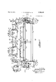
Figure 1 is a front elevation of a shears embodying the improvements of our invention. Portions of the structure are cut away to disclose certain features of internal con- 0 struction.
Figure 2 is an end elevation of tie shears viewed in the direction of the arrow 2 of Figure 1. The driving motor and reduction gears are omitted from this view in order to disclose the brake construction at the far end of the shear driving shaft.
Figure 3 is a schematic wiring diagram showing the electrical connections within the device.
Figure 4 is a transverse sectional elevation viewed as indicated by the line H of Figure 1. included also in this view is a fragmentary portion of the machine that feeds material to the shears.
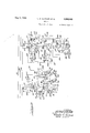
Figure 5 is a fragmentary end elevation of the shears viewed in the direction of the arrow 5 of Figure 1.
This shears of our invention is particularly useful in conjunction with machines such as those used to imprint the decorative clesigns on linoleum. Ordinarily the linoleum is fed through such machines in successive steps, say eighteen inches at atime. For convenience in commercial distribution it is preferable to cut the printed material into lengths that will form suitable sized rolls containing say thirty lineal yards of material.
The material cannot be formed into rolls immediately after leaving the printing machine however, because the freshly applied coloring materials require considerable time to dry. It is accordingly necessary to pull the freshly printed material onto some suitable type of drying rack, which in turn necessitates that the leading endof the strip be engaged by a clamp in a rather secure manner as it requires a comparatively strong pull to drag a long length of material onto a rack.
To the best of our knowledge no clamp has yet been devised that will hold the end of the material without spoiling a portion of the material itself or the freshly applied coloring matter vthereon. Accordingly such clamp wastage appears unavoidable, but it is not particularly costly as the loss due to the clamp alone amounts to only about two inches in a thirty yard strip, This is not the only loss involved however, as is evidenced by the following discussion: If a cut is made at the end of the 61st eighteen inch step as is the usual practice, the resulting unspoiled length of material would be thirty yards and sixteen inches; viz. thirty and one-half yards minus the two inches wasted by the clamp. Assuming that the material is two yards wide (the usual width of commercial linoleums), thiswould result in sixty and one-half square yards plus a fraction of a yard which is less than a half square yard. This fraction must also be considered as waste, because it is not sale able since the trade is accustomed to buying and selling in accord with an integral number of half square yards, not dealing in fractions of less than a half yard. In other words, of the length thirty yards and sixteen inches only thirty yards and nine inches would be saleable; the remaining seven reference numeral 13, by
inches of length being wasted to the manufacturer.
This shears of our invention reduces this loss to the amount of material spoiled by the clamp and enables the manufacturer to obtain full credit for the amount of matcrial actually supplied. To better understand this feature assume that a cut has just been made at the leading edge of a step and that the edge of the material is even with the edge of the shears. If the printing machine is then run for 60 steps and a cut is made the roll will have two inches of spoiled material on one end and is hence unsaleable for full value. If the machine is run for 61 steps and a cut made, the manufacturer loses seven inches of material. When using the shears of our invention the machine is run for 60 steps and then the shears is shifted along the material to cut a length of 60 steps plus two inches or of a step. When the two inch length spoiled by the clamp is later cut off this leaves a perfect and saleable roll and the wastage is reduced to a minimum.
After each succeeding 60 steps the shears is shifted two inches until eight shifts have been made, after which the shears returns to the initial point and the machine is run for 61 steps. The cut is then made at the leading edge of a step and the cycle is repeated. The cutting wastage may thus be reduced about 89% of the amount heretofore allowed. V
The shears of our invention are used to out 01f material being fed through a machine in successive steps, and in terms of broad inclusion comprlse shears and mechanism for shifting the position thereof in time with movement of the material so that each successive length of material severed is equal to that of a given integral number of steps plus a fraction of one step. In order to insure the proper timing of the shift the shifting mechanism is preferably interconnected with the shears operating mechanism and with the material feeding mechanism and it is so shown and described herein.
In terms of greater detail the shears of our invention are mounted on a substructure comprising the box-like end members 6 and '7 having an interconnecting cross beam 8 fixed on the lower ends thereof. As it is sometimes desirable to move the shears structure as a whole the wheels 9 and 11 are journalled subjacent the members 6 and 7 in suitable brackets 12 fixed thereon.
As shown in Figure A the shears structure is preferably set up for operation with a printing machine, identified by the general fixedly attaching the sub-structure to the frame 14 of the mac lzline by means of suitable brackets 16 and 1 The crank The shear mechanism proper is supported on the end posts 18 and 19 which are slidably mounted on the sub-structure members 6 and 7 respectively. As can best be seen in Figure 1 this sliding engagement is provided for by suitable flanges 21 formed on the inner and outer sides of the lower ends of posts 18 and 19,- and the guide flanges 22 and 23 held onthe members 6 and 7 by the bolts 2%.
The lower shear blade 26 is mounted on a cross beam 27 which is held on the posts 18 and 19 by the bolts 28. In order that the blade may be adjustably positioned with respect to the beam 27 it is preferably held thereonby the counter sunk flat head machine bolts 29 which pass through the blade and engage the elongated slots 31 in the beam. The bolts are locked in their adjusted position by the nuts 32 in the usual manner.
The upper shear blade 33 is fixed on a beam which is movably supported from a pair of cross beams 35 and 36 held on the posts 18 and 19 by the bolts 37. These cross beams are further reinforced against transverse deflection adjacent the center by a top bracket 38.
The shearing action is provided by the vertical movement of the beam 34: and hence of blade 33. The beam is constrained to vertical movement by suitable guide flanges 39 on the posts 18 and 19 and by supplementary flanges 41 on beam 34. The outer ends of the beam are further supported against end thrust by the rollers 42 suitably journalled on the posts 18 and 19 in positions to engage the ends of the beam.
The actuating force is impressed on beam through the medium of the two crankshafts l3 journalled on the cross beams 35 and 36 in the horizontally split pillow blocks pins do are journalled in blocks 47 slidably mounted between the sets of guide rails A8 and 49 which are fixed in spaced relationship on top of beam 3t. When the crankshafts 43 are turned through one revolution the beam 3a is thus moved down and back to effect a cut.
Motive power for the crank shaft is derived from a suitable prime mover such as the motor 50, preferably through the medium of a magnetic clutch 51, shafting 52 and the speed reducers 53 all of well known commercial types. The motor and speed reducers are supported respectively by bracket 54 fixed on post 18 and by brackets 56 fixed on beam 36.
As indicated diagrammatically in Figure 4 the strip 57 of linoleum or similar material is fed through the machine 13 and between the shear blades by an endless belt or chain 58 having the sharpened spikes 59 projecting therefrom.
An intermittent or step by step movement is imparted to the belt 58 by a Geneva Star cam 61 driven from a suitable source of power by a crank 62 and in turn driving a sprocket wheel or pulley 63 through the medium of interconnecting gears 64 and 66. For the sake of illustration herein it is assumed that the belt driving mechanism just described is so proportioned as tomove the strip 57 eighteen inches at each step. It is further assumed that the clamp 67 which engages the leading end of the strip to. pull it away from the machine spoils two inches of material. The problem then is to time and position the cutting of the strip so that the remaining seven inches of unspoiled material in the end step will not be lost to the manufacturer. This may be accomplished by making the next cut the desired distance, assumed to be thirty yards or steps in the example selected for illustration, away from the edge 68 of clamp 67. Or in other words the next out should be made sixty and one ninth steps from the edge 69 of the preceding cut.
It is not feasible to cut the strip while it is in motion because of its irregular velocity, and also because of the difficulty of accelerating and decelerating the heavy shears structure without imposing undesirable stresses and vibrations on the other parts of the machine. Accordingly it is preferable to shift the shears in the direction from which the material is being fed in order to properly position the next cut, and then to time the operation of the shears so that the cut is made while the material is stationary.
It has already been mentioned that the posts 18 and 19, which support the shears proper, are slidably mounted on the substructure. The force to slide the shears to and fro is preferably derived from a suitable prime mover such as the electric motor 71 mounted on a bracket 72 fixed on the substructure member 6. The force is transmitted from the motor successively to a speed reducer 73 of a well known commercial type, a pinion 74 fixed thereon and engaging an intermediate gear 76 fixed on a shaft 77 journaled on the members 6 and 7, and the gears 78 and 7 9 fixed on shaft 77 and respectively engaging the racks 81 and 82 fixed on the under sides of the posts 18 and 19. The shaft 77 is also further supported by a bearing 83 supported by a pedestal 84 mounted on the cross beam 8.
The control apparatus for the shear operating mechanism can best be explained with reference to Figure 3. In this view the circuit identified by the general reference numeral 86 controls the actuation of the shear blade; and the circuit identified by the general reference numeral 87 controls the shear shifting mechanism.
Referring first to circuit 86 the motor 50,
l which is assumed to be of the three phase type,.is connected to the conductors 88, 89, 90 of a suitable source of power through a path. comprising the motor leads 9'1, 92, and 93, the magnetic starting switch 94, and the leads 95, 96 and 97. Two of the motor leads are protected by the fuse blocks 98in the usual manner.
One terminal of coil 102 is connected to lead .96 through a thermal overload relay 103, and the other terminal of coil 102 is connected to lead 97 through the starting push button 104 and also through a parallel circuit including the stop push button 106 and the holding contactor 101.
The shear driving motor can thus be started and stopped independently of the remainder of the circuit by operating push buttons 104 and 106, but it does not start moving the shear until the magnetic clutch 51 is closed.
It is to be noted at this point that the speed reducers 53 are normally of the worm gear type and are therefore practically irreversible and tend to hold the shear blade stationar when the motor is not in o eration, but neverthless, in order to more closely position the auxiliary control apparatus associated with the shear, and to insure safety to the operators, we prefer to employ a locking brake on the shear drive.
' Such a locking brake is shown mounted on a bracket 107 fixed on post 19 and comprises a brake drum 108 fixed on a shaft 109 which is locked for rotation with the drive shafts 52 through a speed reducer 53. A. suitable bearing 111 held on post-19 provides support for the outer end of shaft 109.
The outer surface of drum 108 is engaged by the arcuate brake bands 112, and 113 which are pivotally mounted on a post 114 fixed on bracket 107. These bands are normally held in locking engagement with the drum by means of a spring-116 interposed between the upper ends of the bands. The disengagement of the brake bands from the drum is accomplished through the medium of a solenoid 117 which pulls down on the magnetic plunger 118 when energized.
The plunger pulls down on the end of a lever 119 fulcrumed on the upper end of band 113. Lever 119 is connected to the upper end of band 112 by means of a toggle link 121 so that the downward movement of plunger 118 forces the brake bands apart and frees the brake drum for rota tion.
Accordingly after motor 50 is running it remains to close the clutch 51 and release the brake by energizing solenoid 117 in order to make a cut. This may be accomplished as'shown in circuit 86 of'Figure 3 by means of the interconnected magnetic switches 122, and 123 of a well known commercial type. The holding. coil 124 of switch 122 has one terminal connected through a lead 126 to a motor lead 91 which renders switch 122 inoperative unless the motor is running. The other terminal of coil 124 is connected to motor lead 92 through a path comprising the conductors 127 and 128, the cut push button 129 and a conductor 131. Then push button 129 is closed coil 124 closes the contactors 132, 133, and 134 of switch 122. Holding coil 124 then remains energized through a circuit comprising the conductor 127, contactor 133, conductors 136 and 137, the shear stop timing cam 138, and a conductor 139. The timing cam v138 is mounted on an extension of a crank shaft 43 and is thus fixed for movement with the shear blade. It
is formed of a conducting segment 141 and an insulating segment 142. The fixed contactors 143 are so spaced and positioned as to interrupt the circuit through holding coil 124 as the insulating segment 142 passes under them after the shear has made a cut and returned to its position of rest.
The shear does not start down however, until switch 123 is closed and its closing is timed in accordance with the'position of the material in the printing machine by means of a shear cut timing cam 144 which may be conveniently fixed for rotation with sprocket 63 as shown in Figure 4.
Push button 129 having been closed momentarily to close switch 122, the closing coil 151 of switch 123 is connected across leads 91 and 92 through a path comprising the conductors 152, 153, 154, out timing cam 146, contactor 132, and conductor 156. The actual closing of switch 123 does not occur until the segment 147 engages contactors 148 as previously described, but as soon as that occurs switch 123 closes, the brake is released, and the magnetic clutch is closed to start the shear.
Clutch 51 is preferably energized from a suitable source of direct current through the conductors 157 and 158. Conductor 157 is connected directly to a terminal of the coil of clutch 51 and the circuit is completed through a contactor 159 of switch 123. The resistor 161 is shown connected in parallel with coil 51 and serves the purpose of dissipating the energy stored in the magnetic field of the clutch when contactor 159 is subsequently opened.
are connected to the leads 91 and 92 throu h the contactors 162 and 163, so that the bra e is released as switch 123 is closed.
In order that the stop timing cam 138 may surely stop the shear after one cut, the cut timing cam 146 is adjusted to pass on over contacts 148 before it actually comes to rest. It thus closes switch 123 and having performed that function clears the circuit and the contactor 164 of switch 123 maintains the circuit through holding coil 151.
Then when insulating segment 142 of the stop timing cam 138 passes under the contactors 143 the circuits through both holding coils 124, and 151 are interrupted, and switches 122 and 123 are opened.
'As an additional safety measure for the operators a suitable transformer 166 is connected across the motor leads 91 and 92 and serves to energize the light bulb 167 whenever motor 50 is in operation. In order to give warning that the shear is coming down a second light or bell 168 is connected in parallel with light 167 through the contactor 134 of switch 122. Warning is thus given to the operators when switch 122 closes for a out. While discussing this point of safety it might be noted also that push button 129 should be placed in a relatively inaccessible position where it cannot be inadvertently, closed.
As shown in circuit 87 of Figure 3 the shifting'of the shear is controlled through the medium of the magnetic switches 171 and 172, a time delay relay 173, a forward limit switch 174, a reverselimit switch 176, a shift stop timing cam 177 which is operatively engaged with the shift drive shaft 77 as shown in Figure 1, and a shift start timing cam 178 which is mounted on a shear crankshaft 43 as shown in Figure 2.
The limit switches 174 and 176 are shown in Figure 4 supported on the brackets 179 which are adjustably held by the screws 181 on the brackets 182 fixed on the sub-structure member 7. Reverse limit switch 174 is normally open and has a projecting arm 183 which is positioned to be pressed back by the post 19 at the end of its travel to close the contactors 184. Forward limit switch176 is normally closed and is similarly arranged and positioned to be opened by the post 19.
The motor 71 is connected to the conductors 88, 89, 90 through a path comprising the leads 186, 187, and 188, the switch 171, and the conductors 189, 190 and 191. Switch 171 has two independent sets of line contactors actuated respectively by the holding coils 192 and 193. Set 194 associated with coil 192 causes the motor to rotate in a direction to move the shear toward the printing machine; and set 196 associated with coil 193 causes a retrogressive movement of the shears away from the machine. Two of the motor leads are protected against overload by the fuse blocks 197 in the usual manner. In order to closely position the stopping of the shear after a shift .a solenoid operated brake 198 is operatively engaged with the outer end of shaft 199 of motor 71. The solenoid 201 of the brake is connected across the motor leads 186 and 187 so that the brake releases when the motor starts and is automatically applied when the current to the motor is interrupted.
The shift start timing cam 178 is disposed so that the conducting segment 202 engages the contactors 203 just before the shear comes to a rest after a cut. This energizes the actuating coil 204 of time delay relay 173 by connecting its terminals across the conductors 190 and 191 through a path comprising the conductor 206, overload relay 207, and conductors 208, 209 and 211. This closes contactor 212 of relay 173 immediately thus maintaining the circuit through coil 204 via contactor 213 to lead 211 after segment 202 has passed over contactors 203.
After a predetermined interval which is made sufficiently long to insure that the material and operators are clear, say an interval of fifteen seconds, the time delay relay closes contactor 214 and opens contactor 213. The closing of contactor 214 connects the holding coil 192 across the conductors 190 and 191.
This circuit comprises conductor 216, relay 207 and conductor 206 on one side; and comprises a conductor 217, a contactor 218, a conductor 219, contactor 214 and conductors 221, 222 and 211 on the other side.
Holding coil 192 closes the contactors 194 to start the motor 71, and at the same time closes contactor 223 to maintain a closed circuit from coil 192 to conductor 191 when contactor 213 opens to break the circuit through coil 204 which permits contactor 214 to open. Contactor 223 is connected to conductor 191 through the conductor 224, and is connected to coil 192 through a path comprising conductor 226 shift stop timing cam 177, conductor 227, conductor 219, contactor 218, and conductor 217.
The period of operation is determined by the speed ratio of the gear trains 231 and 232 interconnecting cam 177 with the shift drive shaft 77. In the example selected for illustration it is assumed that cam 177 is timed so as to permit the shear to shift two inches at a time. The shear thus shifts each time a cut is made and cam 178 connects contactors 203. Limit switch 174 is positioned so that it is closed at the end of the eighth shift. This connects holding coil 233 of coil 192. Contactor. 238 closes a circuit from coil 233'to conductor 191 via a path comprising conductors 241 and 242, limit switch 176 and conductor 243. This insures a continuation of energizing currentfor coil 233 after the return movement of the shear permits limit switch .174 to open again.
The switches remain set up in this position while the eighth length is being run through the machine. When the cut is next made and cam 178 energizes coil 204 of the time delay relay 173, the coil 193 is energized through a circuit comprising a conductor 244, relay 207 and conductor 206 on the one side; and through a conductor 246, contactor 239, conductor 219, contactor 214 and conductors 222 and 211 on the other side. Coil 193 then closes the contactors 196 and the motor starts moving the shear away from the printing machine. coil 193 energized after the time delay relay opens a contactor 247 is also closed by coil 193 to close a circuit around. contactor 214 through a path comprising a conductor 248, limit switch 176 and conductor 243. The shear thus continues to move back until it trips open the limit switch 176 which interrupts the control circuits and brings the motor to a stop. 1
The shear is then back to its original position where the next cut will be made at the end of a step. It is accordingly necessary to run 61 steps through the machine for the ninth length in order to leave two inches of material for the clamp on the leading end of a 60 step long unspoiled strip.
' It is also desirable to provide a counting or measuring device associated with the printing machine to signal the operator when a cut is to be made and one such device is'shown in Figure 4. A ratchet wheel 251 having a worm pinion 252 fixed for rotation therewith is journalled on a suitable support 253. A lever 254 is also journalled on support 253 concentrically with but independently of wheel 251. Lever 254 is supported in a position to be struck by the driving pin 256 in arm 62 as it moves as indicated by arrow 257.
It is desired to move the material 60 steps eight times and 61 steps onceduring each cycle. Accordingly a worm gear 262 is meshed with pinion 252 of such size as to make one complete revolution for every 541 impulses given to wheel 251 by the pawl. Gear 262 is fixed on a shaft 263 journalled in a suitable support 264. A disk 266 preferably made of an insulating material is also fixed on shaft 263 for rotation with gear 262. Nine conducting segments 267 are fixed about the periphery of disk 266 to successively close a circuit through the fixed contacting fingers 268. Fingers 268 are connected in series with a source of electric current such as the transformer 269, and a signalling device such as the electric bell 271. The segments are so spaced as to cause the bell to ring after the machine has run through 60 steps of material eight successive times, and then to ring once after a 61 step length is run through.
The device thus signals the operator when a cut is to be made, which prevents the costly errors that would otherwise surely occur.
lVe claim:
1. The combination in a machine having means for feeding material therethru in successive steps, of a shears for cutting the ma terial into lengths, and means for shiftmg the position of the shears to make each length equal to an integral number of steps plus a fraction of one step.
2. The combination in a machinev having means for feeding material therethru in successive steps, of a shears for cutting the material into lengths, means for shifting the position of the shears from an initial position toward the machine to make each length equal to an integral number of steps plus a fraction of one step, and means for automatically returning the shears to the initial position after a selected number of shifts.
3. The combination in a machine having means for feeding material therethru in successive steps, of a shears for cutting the material into lengths, and means operative in accordance with the movement of the material for shifting the position of the shears to make each length equalto an integral number of steps plus a fraction of one step.
4. The combination in a machine having means for feeding material therethru in successive steps, of a shears for cutting the material into lengths, means for shifting the position of the shears in successive intervals in a direction opposed to the direction of feed to make each length equal to an integral number of steps plus a, fraction of one step, and means providing for the retrogressive movement of the shears. V
5. The combination in a machine having means for feeding material therethru, of a shears for cutting the material into lengths, a mounting providing for shifting of the shears to and fro in the machine, actuating means associated with the mounting, and control means for the actuating means operative in time with the cutting movement of the shears and the movement with which the material is fed through the machine for shifting the position thereof a predetermined amount.
6. The combination in a machine having means for feeding material therethru, of a shears for cutting the material into lengths, a mounting providing for shifting of the shears to and fro in the machine, actuating means associated with the mounting, and control means for the actuating means operative after a preselected interval of time following the cutting movement of the shears and operative in time with the movement of the material through the machine for shifting the position thereof a predetermined amount.
7. The combination in a machine having means for feeding material therethru, of a shears for cutting the material into lengths, a mounting providing for shifting of the the shears to and fro in the machine, an electric motor associated with the mounting for the actuation thereof, a switch for controlling the motor, a cam associated with the shears and the switch for starting the motor after each cutting movement of the shears, and a second cam associated with the mounting and the switch for stopping the motor.
8. The combination in a machine having means for feeding material therethru, of a shears for cutting the material into lengths, a mounting providing for shifting of the shears to and fro in the machine, an electric motor associated with the mounting for the actuation thereof, a switch for controlling the motor, a cam and time delay mechanism associated with the shears and the switch for starting the motor after a preselected interval of time following each cutting movement of the shears, and a second cam associated with the mounting and the switch for stopping the motor.
9. The combination in a machine having means for feeding material therethru, of a shears for cutting the material into lengths, a mounting providing for shifting of the shears to and fro in the machine, an electric motor associated with the mounting for the actuation thereof, means associated with the shegrs and the motor for starting said actuation after each cutting movement of the shears, and means associated with the mounting and the motor for stopping said actuation after a preselected length of shift.
10. The combination in a machine having means for feeding material therethru, of a shears for cutting the material into lengths,
a mounting providing for shifting of the shears to and fro in the machine, an electric motor associated with the mounting for t 1e actuation thereof, means including time delay mechanism associated with the shears and the motor for starting said actuation after a preselected time interval following each cutting movement of the shears, and means associated with the mounting and the motor for stopping said actuation after a preselected length of shift.
11. The combination in a machine having means for feeding material therethru, of a shears for cutting the material into lengths, a mounting providing for shifting of the shears to and fro in the machine, an electric motor associated with the mounting for the actuation thereof, means-associated with the shears and the motor for starting said actuation after each cutting movement of the shears and in time with the movement of the material through the machine, a means associated with the mounting and the motor for stopping said actuation after a preselected length of shift, means associated with the mounting and the motor for initiating a retrogressive movement of the shears after a selected number of shifts, and means for stopping the retrogressive movement at a preselected point.
12. The combination in a machine having means for feeding material therethru, of a shears for cutting the material into lengths, a. mounting providing for the shifting of the shears to and fro in the machine, an electric motor associated with the mounting for the actuation thereof, a switch for controlling the motor, a cam associated with the shears and the switch for starting the motor after each cutting movement of the shears, a second cam associated with the mounting and the switch for stopping the motor, a limit switch associated with the mounting and the motor switch operable to initiate a retrogressive movement of the shears after a selected number of shifts, and a second limit switch operable to stop the retrogressive movement.
13. The combination in a machine having means for feeding material therethru in successive steps, of a shears for cutting the material into lengths, actuating means for the shears, means interconnecting the actuating means with the feeding means so that the shears can be operated only when the material is at rest, a mounting providing for shifting of the shears to and fro in the ma chine, actuating means associated with the mounting, and control means for the shift actuating means operative in time with the cutting movement of the shears for shifting the shears a predetermined distance after each cut.
14. The process of cutting a web having an intermittent movement of unit steps into lengths exceeding by a fraction of a step an integral number of steps, which comprises feeding the web an integral number of steps toward the cutting means, moving the cutting means against the direction of feed for the said fraction of a step, and cutting'the web.
15. The combination in a machine having means for feeding material therethru in successive steps, of a shears for cutting the material into lengths, actuating means for the shears, means interconnecting the actuating means with the feeding means so that the shears can be operated only when the material is at rest, a mounting providing for shifting of the shears to and fro in the machine, actuating means associated with the mounting, control means for the shift actuating means operative in time with the cutting movement of the shears for shifting the shears a predetermined distance after each of a plurality of cuts, and control means associated with the mounting and the actuating means therefor providing for the retrogressive shifting of the shears.
16. The combination in a machine having means for feeding material therethru, of a shears for cutting the material into lengths, a mounting providing for shifting of the shears to and fro in the machine, an electric motor associated with the mounting for the actuation thereof, a switch for controlling the motor, control means for the switch ass0- ciated with the shears for closing the motor controlling switch after each cutting movement of the shears, and control means associated with the mounting for stopping the movement thereof after a predetermined length of travel.
17 The process of cutting a web having an intermittent movement of unit steps into lengths exceeding by a fraction of a step an integral number of steps, which comprises feeding the web an integral number of steps toward the cutting means, moving the cutting means against the direction of feed successively as many times as there are fractions in a unit step less one, effecting the recovery movement of the cutting means to its original position and feeding the web toward the cutting means the same integral number of steps as before plus one step.
18. The combination in a machine having means for feeding material therethru in successive steps, of a shears for cutting the material into lengths, means for shifting the position of the shears to make each length equal to an integral number of steps plus a fraction of one step, and means for returning the shears after a selected number of shifts.
19. The combination in a machine having means for feeding material therethru in successive steps, of a shears for cutting the material into lengths, means for shifting the position of the shears to make each length equal to an integral number of steps plus a fraction of one step, and means for effecting the recovery movement of the shears.
20. The process of cutting a Web having an intermittent motion of unit steps into lengths exceeding by a fraction of a step an integral number of steps, which comprises feeding the Web an integral number of steps past the cutting means, moving the cutting. means a distance equal to said fraction of a step, and cutting the Web.
In testimony whereof, We have hereunto set our hands.
LELAND S. ROSENER. WILLARD H. NUTTING.
Priority Applications (1)
| Application Number | Priority Date | Filing Date | Title |
|---|---|---|---|
| US548618A US1908448A (en) | 1931-07-03 | 1931-07-03 | Shears |
Applications Claiming Priority (1)
| Application Number | Priority Date | Filing Date | Title |
|---|---|---|---|
| US548618A US1908448A (en) | 1931-07-03 | 1931-07-03 | Shears |
Publications (1)
| Publication Number | Publication Date |
|---|---|
| US1908448A true US1908448A (en) | 1933-05-09 |
Family
ID=24189658
Family Applications (1)
| Application Number | Title | Priority Date | Filing Date |
|---|---|---|---|
| US548618A Expired - Lifetime US1908448A (en) | 1931-07-03 | 1931-07-03 | Shears |
Country Status (1)
| Country | Link |
|---|---|
| US (1) | US1908448A (en) |
Cited By (2)
| Publication number | Priority date | Publication date | Assignee | Title |
|---|---|---|---|---|
| US3389627A (en) * | 1966-08-31 | 1968-06-25 | Nat Electric Welding Machines | Trimming mechanism for strip welder |
| US20100269664A1 (en) * | 2009-04-22 | 2010-10-28 | Mike Majchrowski | Servo pouch knife assembly |
-
1931
- 1931-07-03 US US548618A patent/US1908448A/en not_active Expired - Lifetime
Cited By (2)
| Publication number | Priority date | Publication date | Assignee | Title |
|---|---|---|---|---|
| US3389627A (en) * | 1966-08-31 | 1968-06-25 | Nat Electric Welding Machines | Trimming mechanism for strip welder |
| US20100269664A1 (en) * | 2009-04-22 | 2010-10-28 | Mike Majchrowski | Servo pouch knife assembly |
Similar Documents
| Publication | Publication Date | Title |
|---|---|---|
| US3089661A (en) | Automatic cigarette paper splicer | |
| US2254394A (en) | Cutoff applying means | |
| US3481746A (en) | Interleaving of food slices | |
| US3252671A (en) | Method of splicing cigarette paper | |
| US2403147A (en) | Automatic winding machine | |
| US3114282A (en) | Apparatus for the transverse severance of continuously moving tubular structures | |
| US1908448A (en) | Shears | |
| US2618047A (en) | Length control apparatus | |
| US1920591A (en) | Reciprocating mechanism | |
| US2253367A (en) | Boosting mechanism for bread slicing machines | |
| GB1440927A (en) | Web cutting device | |
| US3504718A (en) | Apparatus for cutting a continuously moving strip of material | |
| US3158522A (en) | Configured web-cutting apparatus | |
| US3586577A (en) | Bag sealing machine | |
| US3620434A (en) | Automatic carton stapling machine | |
| US2519159A (en) | Apparatus for sampling strip material | |
| US2641974A (en) | Apparatus for cutting and stacking sheets | |
| US2255498A (en) | Condenser winding machine | |
| US1588018A (en) | Clay-cutting apparatus | |
| US2807293A (en) | Preset for sawmill carriages | |
| US3438296A (en) | Flying shear with alternately operative drive motors | |
| US2782709A (en) | Bundle tying apparatus | |
| US3066709A (en) | Position control for power driven mechanism | |
| GB259632A (en) | Improvements in web winding machines | |
| US2395562A (en) | Length control apparatus |