US1908446A - Electrical system and apparatus - Google Patents
Electrical system and apparatus Download PDFInfo
- Publication number
- US1908446A US1908446A US460557A US46055730A US1908446A US 1908446 A US1908446 A US 1908446A US 460557 A US460557 A US 460557A US 46055730 A US46055730 A US 46055730A US 1908446 A US1908446 A US 1908446A
- Authority
- US
- United States
- Prior art keywords
- terminal
- circuit
- coil
- conductor
- dynamo
- Prior art date
- Legal status (The legal status is an assumption and is not a legal conclusion. Google has not performed a legal analysis and makes no representation as to the accuracy of the status listed.)
- Expired - Lifetime
Links
- 239000004020 conductor Substances 0.000 description 120
- 238000010438 heat treatment Methods 0.000 description 27
- 238000004804 winding Methods 0.000 description 27
- 239000000446 fuel Substances 0.000 description 22
- 230000009471 action Effects 0.000 description 13
- 230000001276 controlling effect Effects 0.000 description 13
- 238000002485 combustion reaction Methods 0.000 description 8
- 230000000694 effects Effects 0.000 description 7
- 210000003414 extremity Anatomy 0.000 description 5
- 230000007423 decrease Effects 0.000 description 4
- 238000010586 diagram Methods 0.000 description 4
- 238000010276 construction Methods 0.000 description 3
- 210000003141 lower extremity Anatomy 0.000 description 3
- 239000000203 mixture Substances 0.000 description 3
- 230000001681 protective effect Effects 0.000 description 3
- 238000009877 rendering Methods 0.000 description 3
- 239000002131 composite material Substances 0.000 description 2
- 230000006835 compression Effects 0.000 description 2
- 238000007906 compression Methods 0.000 description 2
- 239000011810 insulating material Substances 0.000 description 2
- 239000002184 metal Substances 0.000 description 2
- 206010041953 Staring Diseases 0.000 description 1
- 230000015572 biosynthetic process Effects 0.000 description 1
- 150000001875 compounds Chemical class 0.000 description 1
- 230000001419 dependent effect Effects 0.000 description 1
- 230000005484 gravity Effects 0.000 description 1
- 239000007788 liquid Substances 0.000 description 1
- 230000005415 magnetization Effects 0.000 description 1
- 238000004519 manufacturing process Methods 0.000 description 1
- 239000000463 material Substances 0.000 description 1
- 230000004048 modification Effects 0.000 description 1
- 238000012986 modification Methods 0.000 description 1
- 230000007935 neutral effect Effects 0.000 description 1
- 230000002035 prolonged effect Effects 0.000 description 1
- 230000009467 reduction Effects 0.000 description 1
- 230000001105 regulatory effect Effects 0.000 description 1
- 238000000926 separation method Methods 0.000 description 1
- 239000007787 solid Substances 0.000 description 1
- 238000009834 vaporization Methods 0.000 description 1
- 230000008016 vaporization Effects 0.000 description 1
Images


Classifications
-
- H—ELECTRICITY
- H02—GENERATION; CONVERSION OR DISTRIBUTION OF ELECTRIC POWER
- H02P—CONTROL OR REGULATION OF ELECTRIC MOTORS, ELECTRIC GENERATORS OR DYNAMO-ELECTRIC CONVERTERS; CONTROLLING TRANSFORMERS, REACTORS OR CHOKE COILS
- H02P9/00—Arrangements for controlling electric generators for the purpose of obtaining a desired output
Definitions
- This invention relates to electrical systems and apparatus and has particular rela tion to such systems and apparatus commonly designated as isolated generating plants or farm-lighting plants.
- One object of the invention is to provide a system and apparatus of the above-indicated character which shall involve certain new and advantageous protective features.
- Another object of the invention is to provide new and advantageous means for controlling the normal operation of a system and apparatus of the character indicated, in eluding the provision of means whereby either automatic or non-automatic operation may be accommodated, as desired.
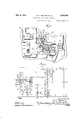
- Figure 1 is a diagrammatic representation of certain apparatus and electrical circuit connections therefor, constituting a preferred embodiment of the invention
- Fig. 2 is a detail View, partly in elevation and partly in section, of part of the apparatus shown in Fig. 1 this apparatus being shown enlarg d in Fig. 2 over the showing of the same apparatus in Fig. 1;
- Fig. 3 is a simplified schematic diagram of the apparatus and circuit connections of the system shown in Fig. 1, including a change-over switch arranged and connected to accommodate either automatic or nonautomatic operation of the system, as fully described hereinafter;
- Fig. 4 is a simplified schematic diagram of the same apparatus and circuit connections, with the above-mentioned change-over switch in a position to accommodate automatic operation, all of the parts which are inoperative while said switch is in such position being omitted;
- Fig. 5 is a simplified schematic diagram of the same apparatus and circuit connections when the change-over switch is in its non-automatic position, the parts which are inoperative while said switch is in such position being omitted.
- the system disclosed comprises an internal combustion engine diagrammatically shown at 11 as being connected to a shaft indicated at 12, to which the armature 13 of a direct current dynamo-electric machine is also connected.
- the engine 11 is provided with a carburetor 14 to which liquid fuel may be supplied through a pipe or conduit 15 from any suitable source (not shown). Vaporized fuel from the carburetor 14 is supplied through a connection including a throttle valve 16 or other suitable means for controlling the rate of fuel supply to the engine. The manner of regulating the degree of opening of the throttle valve 16 will be de scribed hereinafter.
- the engine 11 is also provided with a spark plug 17 and a timer 18 which controls the energization of an ignition device or spark coil 19 to provide proper ignition for the engine.
- the dynamo-electric machine which comprises the arlnature 13 also comprises a shunt field-magnet winding 20 and a series fieldmagnet winding 21.
- This dynamo-electric machine is adapted to operate both as a motor for starting the engine 11 and as a genera-tor to be driven by said engine after the latter is started.
- W hen the dynamo-electric machine is operating as agenerator, it is adapted to supply electrical energy to a load circuit comprising conductors 22 and 23 and any desired energy-consuming devices 24 which may be connected between said conductors.
- a storage battery 25 is also adapted to supply energy to the load circuit when the dynamo-electric machine is not operating, and to receive energy from said dynainc-electric machine when the latter is in operation.
- the apparatus for controlling the operation and circuit connections of the above-described apparatus is advantageously mounted in part on each face of a panel board or the like, the front face of which is indicated at 26? and the rear face of which is indicated at 26
- the two faces of the panel board are both diagrammatically shown in front elevation and in laterally displaced relation to each other.
- On the rear face 26 of the panel board are mounted a plurality of elec trical terminals 27, 28, 29, 30, 31, 32, 33, 34, 35 and 36, to which conductors extending to the external apparatus of the system are connected, as hereinafter described.
- the positive terminal of the armature 13 is connected through a conductor 37 to the terminal 35, and the negative terminal of Said armature is connected through a conductor 38 to the terminal 32.
- the shunt field-magnet winding 20 of the dynamo-electric machine is connected through conductors 39 and 40 to the terminals 36 and 32, respectively, while the series field-magnet winding 21 is connected through conductors 41 and 42 to the terminals 36 and 33, respectively.
- One terminal of the primary circuit of the ignition transformer or spark coil 19 is connected throu h a conductor 43 to-the terminal 34 on the ack of the anel board, and the other terminal of sai circuit is connected through a conductor 44 to one terminal of the timer 18, the other terminal of which is connected through a conductor 45 to ground.
- One of the secondary or high voltage terminals of the ignition coil 19 is connected through a conductor 46 to the spark plug 17, while the other secondary terminal is directly connected to ground through a conductor 47.
- the load circuit conductors 22 and 23 are respectively connected to the terminals 28 and 27, and the positive and negative terminals of the battery 25 are respectively connected to the terminals 30 and 31 through conductors 48 and 49.
- the terminals 27 and 31 are connected together by a conductor 50 and the terminals 27 and 32 are similarly connected together by a conductor 51.
- the terminal 32 is also connected to ground through a conductor 52. Thus it will appear that the terminals 27 31 and 32 are all permanently maintained at ground potential.
- An alarm device 53 is connected through conductors 54 and 55 to the terminals 27 and 29, respectively.
- An electrical heating coil 56 is preferably located in the fuel intake connection of the engine 11. One terminal of this coil is connected through a conductor 57 to a point of connection 58 with certain other circuits located on the rear of the panel board, as hereinafter described. The other terminal of the heating coil 56 is connected through a conductor 59 to ground.
- a control relay generally designated by the reference character 60 comprises two series-connected coil portions 60 and 60 a magnetizable core member 60 disposed within said coil portions, and a plurality of contact members 60 60*, 60' and 60
- the contact members 60 and 60' are fixed contact members and are respectively adapted to be engaged by the contact members 60 and 60, which latter are electrically and mechanically connected to the core member 60 to be movable therewith under the influence of the coil portions 60* and 60".
- the movable parts of the control relay 60 are preferably also adapted for manual actuation by means of a handle 60 which is mechanically connected to said parts, as shown, but electrically insulated therefrom, as indicated at 60.
- a starting switch generally designated by the reference character 61 comprises two magnet coils 61 and 61", a magnetizable core member 61 located within said coils, and a plurality of contact members 61, 61*, 61' and 61.
- the contact members 61 and 61 are fixed contact members and are respectively adapted to be engaged by the contact members 61 and 61 which latter are mechanically and electrically connected to the core member 61.
- a governor or controlling device for the throttle valve 16, controlling the rate of fuel supply to the engine 11, is generally desi nated at 62 and comprises two magnet coi s 62 and 62 and a magnetizable core member 62, the osition of which is controlled by the energization of the coils 62 and 62*.
- This core member 62 is connected to the throttle valve 16, or other fuel supply ratecontrolling means, through any suitable linkage or other connection which is diagrammatically indicated by the broken line 63.
- the valve 16, or its equivalent is biased toward open, or maximum fuel-supply rate, position, by any suitable means, such as a spring 64.
- a safety device the function of which is described hereinafter, is designated generally by the reference character 65.
- the essential elements of this safety device are a bimetallic or other thermostatic member 65, which also constitutes a contact member, an electrical heating element 65' for said thermostatic member, a movable contact member 65, another movable contact member 65 which is of composite formation and is carried b the movable contact member 65 in electrlcally-insulated relation thereto, and contact members 65" and 65 which are selectively engageable by the movable contact member 65.
- the other parts of the safety device 65 and the details of construction of said device are better shown in Fig. 2 and will be described in connection with said figure hereinafter.
- the front face 26 of the panel board earries an ammeter 66, a line fuse 67, a changeover switch 68 and a battery fuse 69.
- change-over switch 68 is shown as a knifeswitch of the double-pole, double-throw type comprising two blade-supporting terminals 70 and 71, two blades 72 and 73 respectively supported by the terminals 70 and 71, two contact jaws 74- and 75 adapted to be selectively engaged by the blade 72 and two contact jaws 76 and 77 adapted to be selectively engaged by the blade 73.
- the outside terminal of the coil portion 60 of the control relay 60 is connected through a conductor 78 to a point of connection 79 with a conductor 80 which extends from one terminal of the coil 62 of the governor 62 to the contact jaw 76 of the change-over switch 68.
- the common terminal or junction point of the two coil portions 60 and 60 of the control relay 69 is connected through a conductor 81 to the contact 60 of said control relay.
- the outside terminal of the coil portion 60" is connected through a conductor 82 to the contact jaw 77 of the change-over switch 68.
- the fixed contact 60 of the control relay is connected through a.
- the movable contacts 60 and 60 of the control relay are both electrically connected with the core member 60 of said relay, which core member is connected through a conductor 84 to terminal post 85 which is electrically connected to the thermostatic member 65* of the safety device 65, as will appear more clearly hereinafter.
- One terminal of the coil 61 of the starting switch 61 is connected through a conductor 36 to the terminal 27, while the other termi nal of said coil is connected through a conductor 87 to one terminal of the coil 62 of the governor 62.
- the terminal of the coil 61 of the starting switch other than the terminal to which the conductor 33 extends as above stated, is connected through a conductor 88 to the terminal 36.
- the fixed contact 61 isconnected through a conductor 89 to the terminal 33, and the other fixed contact 61 of the star ing switch is connected through a conductor 90 to the blade-supporting terminal 70 of the change-over switch 68.
- the two movable contact members 61 and 61 of the starting switch are both in direct electrical connection with the core member 1 of said switch, which core member is connected through a conductor 91 to one terminal of the electrical heating element 65 the safety device 65.
- This conductor 91 includes the point of connection 58 to which the conductor 57 extends, as previously nescribed.
- the terminal of the coil 62 is connected through a conductor 93 to the terminal 34;, which, as will appear hereinafter, is in direct electrical connection with the contact member 65 of the safety device 65.
- he terminal of the electrical heating element 65 of the safety device 65 is connected through a conductor 94 to the terminal 32 on the rear face of the panel board.
- the contact member 65 of the safety device 65 is connected through a flexible conductor 95 to the terminal 36 on the rear face of the panel board, and the contact member 65 is in direct electrical connection with the terminal 35, as will appear more fully in connection with the des vription of Fig. 2 hereinafter.
- the other fixed contact member 65 of the safety device 65 is connected through a conductor 96 to the terminal 29.
- a conductor 97 extends from the terminal 28 on the rear face 26 of the panel board to one terminal of the line fuse 67, the other terminal of which is connected through a conductor 98 to the blade-supporting terminal 70 of the changeover switch 68.
- a conductor 99 extends from the terminal 30 on the rear face of the panel board to one terminal of the battery fuse 69, the other terminal of which is connected through a conductor 100, the ammeter 66 and a conductor 101 to the contact jaw 74 of the switch 68.
- the blade-supporting terminal 71 of the switch 68 is connected to the contact jaw 74 of said switch through a conductor 102.
- a conducting bracket member 103 which also carries the terminal 85, so that the conductor 8 which is connected to said terminal 85, is indirect, electrical connection with the thermostatic member 65.
- thermostatic member 65 When the safety device 65 is in its normal condition, as illustrated in the drawings, the rightrand end of the thermostatic member 65 makes electrical and mechanical contact with the lower extremity of the contact member 65.
- This contact member 65 is pivotally mounted on a pin 164 and is so biased by a torsion spring 105 that it tends to rotate in a clockwise direction about said pin.
- the pivot pin 104 which carries the contact member 65 is mounted on an adjustable conducting member 106 which is pivoted at its left-hand end on the terminal post 34, to which the conductors 43 and 93 are connected. Since the adjustable member 106 and the pivot pin 104 are of metal or other suitable electrical conducting material it will be seen that the conductors 43 and 93 are permanently electrically connected to the contact member 65.
- the right-hand extremity of the adjustable member 106 is slotted, as indicated at 106, to accommodate a securing screw 107 which may be tightened to press the said extremity of the member 106 firmly against the rear face 26 of the panel board.
- the adjustable member 106 When this screw is loosened the adjustable member 106 may be moved to a limited extent about the pivot provided by the terminal post- 34 to raise or lower the contact member 65 and thereby to vary the distance which the thermostatic member 65 must move from its normal position before disengaging the lower extremity of said contact member 65. When the desired adjustment is made the member 106 is firmly secured in position by tightening the screw 107.
- the composite contact member 65 of the safety device 65 comprises a metallic or other suitable conducting strip 108 and a pin or rivet 109 having a shank portion 109 extending through a hole in the strip 108 in relatively close fitting relation thereto and through a hole of larger diameter in the contact member 65, a head portion 109 overlying the edges of said hole in the strip 108 in electrical contact therewith, and a contacting portion 109 which is adapted to move into contact with the fixed contact member 65 when the contact member 65 is disengaged by the thermostatic member 65.
- the contact member 65 and the conducting strip 108 of the contact member 65 are separated by a strip 110 of insulating material, and the shank and contact face portions 109 and 109 of the contact member 65 are insulated from the contact member 65 by a flanged insulating bushing 111.
- a screw 112 also extends through holes in the contact member 65 and the strip portion 108 of the contact member 65 in electrical contact with the latter.
- This screw is insulated from the contact member 65 by means of a flanged insulating bushing 113.
- the shank of the screw 112 also extends through a hole in a conductor terminal 114 which is firmly secured in electrical contact with the strip portion 108 of the contact member 65 by means of a lock washer 115 and a nut 116 cooperating with the threaded end of the screw 112.
- This terminal member 114 is connected to one end of the flexible conductor 95, the other end of which is connected to the terminal post 36.
- the contact member 65 is permanently electrically connected to the terminal post 36, but is permitted to move to a limited extent with respect to said terminal post by reason of the flexibility of the conductor 95.
- the contact member 65 consists of a headed pin 117, the shank of which extends in freely slidable relation through a suitable hole in an upstanding portion 118 of a fixed bracket member 119 of suitable metal or other electrical conducting material.
- a coil compression spring 120 coacts between the head portion of the pin 117 and the bracket portion 118 to permit said pin to be moved slightly to the right, as viewed in Fig. 2, against the resilient action of said spring. This construction is utilized to insure perfect contact between the contact members 65 and 65 and to accommodate slight variations in the normal position of the contact member 65 dependent upon the action of the thermostatic member 65'.
- the right-hand end portion of the pin 117 is screw-threaded to receive two nuts 121 and 122, between which is clamped a conductor terminal 123.
- This terminal is connected to one end of a flexible conductor 124, the other end of which is connected to the terminal post 35, thereby placing the contact member 65 in permanent electrical connection with the conductor 37, which is also connected to said terminal post.
- the flexibility of the conductor 124 accommodates the slight movements of the contact members 65 and permits said contact member to move slightly to the left when the contact members 65 and 65 are similarly moved upon the former being disengaged by the thermostatic member 65.
- the position of the nuts 121 and 122 may be varied, as desired, to secure the proper extreme left-hand position of the contact member 65.
- the panel board, on the rear face 26 of which the safety device 65 and other parts of the apparatus are mounted is made of suitable insulating material. It will also be noted that the various conductors of the system are illustrated in Fig. 2 as being insulated in the conventional manner.
- FIG. 3 illustrates, in simplified form, all of the circuit connections of the system as shown in Fig. 1, while Figs. 4 and 5 illustrate the connections existing when the change-over switch 68 occupies its right-hand and left-hand positions, respectively.
- the switch 68 itself and all of the parts of the apparatus which are inoperative while said switch occupies the position respectively assumed in each case, are omitted for the purposes of clarity of illustration and description.
- the change-over switch 68 is utilized to accommodate either automatic or nonautomatic operation of the system in a manner which is fully described hereinafter.
- This switch is shown in its right-hand position in Fig. 1, which is the position accommodating automatic operation of the system.
- the circuit connections illustrated schematically in Fig. 4 are those existing when the switch is in such automatic position, while those illustrated in Fig. 5 ar tie connections existing when the switch 68 occupies its left-hand or non-automatic position. It will be understood that all of the following description of operation of the system is applicable to, and understandable by reference to, the circuit connections shown in Fig. 1, and that Figs. 3, 4 and 5 are included and referred to herein merely for the purpose of providing a simpler and more readily understandable illustration of the invention.
- the system is adapted to function so that the dynamo-electric machine will be operated as a motor by energy supplied by the storage battery 25, for the purpose of cranking the internal combustion engine 11. hen the engine 11 is automatically started in this manner the dynamo-electric machine is driven thereby as a generator to supply energy to the load circuit and also to the battery 25.
- This automatic starting operation is initiated by connecting a lamp or other energy-consuming device 24 across the conductors 22 and 23 of the load circuit. Such connect. n completes a circuit from the posilive terminal of the battery 25 through the conductor 48, terminal 30, conductor 99, fuse 69, conductor 100, ammeter 66, conductors 101 and 102, contact 71, blade 73 and contact 7'? of the switch 68. conductor 82, coil (5 portions 60 and 66 of the control relay 60,
- This circuit branch comprises the conductor 81 and extends through the contacts 60 and 60 of the control relay to the core member 60 of said relay. From this point two parallel paths are established, one of which extends through the contacts 6O and 60 of the control relay, conductor 83, coil 61" of the starting switch, conductor 88, terminal 36, conductor 95, contacts 65 and 65 of the safety device 65, conductor 124, terminal 35, conductor 37 ,armature 13 of the dynamo-electric machine, conductor 38, terminal 32, conductor 51, terminal 27 conductor 50, terminal 31 and conductor 49 to the negative terminal of the battery.
- the shunt field winding 20 of the dynamo-electric machine is connected in parallel relation to the armature 13 of said machine and the contacts 65 and 65 of the safety de vice 65, which armature and contacts are connected in series relation to each other.
- This parallel connection of the shunt field winding 20 is completed by means of the conductor 39 extending from one terminal of said shunt field winding to the terminal 36, and the conductor 40 extending from the other terminal of said field winding to the terminal 32.
- the other one of the two parallel circuit branches extending from the core member of the control relay 60 comprises the conductor 84, terminal 85, thermostatic mem ber and contact member 65 of the safety device 65, and the terminal 34, from which terminal the circuit again divided into two parallel branches, one of which includes the conductor 43, the primary winding of the ignition coil 19, conductor 44, timer 18 and conductor 45 to ground.
- the other one of the two last-metnioned parallel circuit branches extending from the terminal 34 comprises the conductor 93, coil 62- of the governor 62, conductor 87, coil 61 of the starting switch 61, and conductor 86, which is connected through the terminal 27 to the negative terminal of the battery 25.
- the coil 61 of the starting switch is connected in parallel circuit relation with the battery 25 in the last-mentioned circuit branch and is, consequently, energized from the battery.
- the coil 61 of said starting switch is also energized by current flowing through said coil and the armature 13 and shunt field winding 20 of the dynamo-electric machine in the first above-mentioned circuit branch.
- the core member 61 of said starting switch is raised to effect engagement between the contacts 61, 61 and 6], 61 respectively.
- the other one of the two parallel paths from the core member 61 of the starting switch comprises the conductor 91, electrical heating element 65 of the safety device 65 and conductor 94 to the terminal 32, from which terminal the circuit is completed to the negative terminal of the battery 25 as above described.
- the conductor 91 of this last-mentioned parallel path includes the junction point 58, ,from which the conductor 57 extends to the electrical heating element 56 for heating the fuel mixture supplied from the carburetor 14 to the engine 11.
- the other terminal of this heating element 56 is connected to ground through the conductor 59, so that said heating element is permanently connected in direct parallel relation to the electrical heating element 65 of the safety device 65. and is energized concurrently therewith.
- the starting current from the battery to the armature of the dynamo-electric means flows through two parallel paths.
- One path is through the coil portion 60 of the device 60 and the coil portion 61 of the device 61.
- the other path is through both of the coil portions 60 and 60 in series, the winding 62 of the governing device 62, the contacts of the device 61, and the series field coil 21.
- the proportionate resistance of each of these circuit paths is such that a sufiicient proportion of the initial starting current passes through the series field coil 21 to start the cranking of the engine. It has been found in actual practice that after this initial current surge has taken place, the shunt field strength is sulficient to keep the engine turning over until it begins to run, even where the series field current decreases to a very low value or to zero.
- the driving relation between the engine and the dynamo-electric machine is reversed so that the latter is driven as a generator. Accordingly, the direction of current flow between the dynamo electric machine and the battery 25 is reversed, which causes a reversal of ener ization of the coil 61 of the starting switc 61.
- the current initially flowing from the battery to the dynamo-electric machine through the coil 61 energized this coil in such direction that it assisted the coil 61 in closing the contacts of the starting switch, but upon reversal of current flow through the coil 61 these two coils oppose each other and cause the contacts of the starting switch to be opened.
- the opening of the contacts 61 and 61 disconnects the series field winding 21, the electrical heating element 65 of the safety device 65 and the fuel intake heater 56 from the battery circuit, while the opening of the contacts 61 and 61 disconnects the series field winding 21 from the said two heating elements. Accordingly, said heating elements, as well as the series field winding 21, are completely disconnected from circuit and do not function further during the continued normal operation of the system.
- the current supplied by the dynamo-electric machine when the latter begins to operate as a generator flows in part to the load circuit and in part to the battery 25 to recharge the latter.
- This current is supplied through the conductor 81 which is connected to the circuit including the battery and the load at the junction point of the two coil portions 60* and 60 of the control relay 60. From this point the current supplied to the load circuit flows through the coil conductor 7 8, and other elements of the circuit in the same mannerv as the current supplied by the battery to the load over the initial starting circuit.
- the negative terminal of the battery 25 and the negative terminal of the dynamoelectric machine are permanently connected together, so that the return circuit from the load to the generator corresponds to the return circuit from the load tothe battery.
- the load 2% is. supplied with energy from the dynamo-electric machine. acting as a generator as long as there is any demand for energy on the load circuit.
- the current flowing from the generator to the load as above described traverses the coil portion 60 of the control relay in the same direction as the current supplied by the battery through the initial starting circuits, so that the direction of energization of this coil portion is unchanged.
- the current flow from the conductor 81 to the positive terminal of the battery is reversed in direction when the dynamo-electric ma chine begins to operate as a generator, and
- this current serves to recharge the battery 25 at a rate determined by the degree of charge of said battery and the voltage of the generator.
- the charging circuit exte. ds through the conductor 81 to the common terminal or junction point of the coil portions 60 and 60 of the control relay 60, from which junction point the circuit may be traced through the same elements included between the positive terminal of the battery and said junction point in the initial starting circuits, but in a reversed direction with respect thereto.
- the negative terminal at the battery 25 being permanently connected to the negative terminal of the dynamoelectric machine as above noted, the return portion of the charging circuit is readily traced through the conductors 49, 50, 51 and 38.
- the coil portion 60 may constitute only a relatively small number of turns as compared with the coil portion 60
- the energization of the operating coil of this relay is so reduced that the relay core member 60 falls by the action of gravity or of a suitable spring, if desired, so that the contacts 60 6 e and 60 G0 are opened, thus completely disconnecting the dynamo-electric machine from t 1e battery and load circuits, and also disconnecting the ignition circuit from both the dynamo-electric machine and the battery, so that the ignition coil 19 can no longer be energized from either of these sources. Accordingly, the engine l1 and the dynamo-electric machine come to rest an l, will so remain until the above-described cycle of operations is repeated by reason of a renewed demand for energy on the load circuit.
- the throttle valve 16 is biased toward open position by the spring or other suitable means, so that the said throttle valve is in its full open position when the plant is not in operation.
- the biasing action of the spring Get or its eq ivalent is opposed by the coil 62" of the governor 62, which, as above described, is connected in series with the coil 61 of the starting switch 61 in a circuit that is connected in parallel relation with the battery and dynamo-electric machine during the starting and running periods of the latter.
- the reduction of the battery voltage due to the relatively heavy starting load energizes the coil 62 to a degree that is less than normal, so that the throttle-closing tendency of said coil is reduced and the throttle is given a relatively high degree of opening to facilitate starting of the engine.
- This action is supplemented by the coil ('32 which opposes the action of the coil 62 and which is energized to an abnormally high degree during the starting period by reason of its connection in the series circuit between the battery 25 and the starting series field winding 21.
- the coils 62 and 62 are both affected during the starting period to produce a large tl rottle opening, desired.
- Prompt starting of the engine is also tacilitated by the use of the heating coil 56 which heats the fuel mixture entering the engine during the starting period and insures complete vaporization of such mixture.
- Such auxiliary heating is not required after the engine starts to operate under its own power, as it then rapidly attains its proper operating temperature so that the fuel will be automatically received by the engine in proper condition. It is for this reason that the heating coil 56 is connected in parallel relation to the heating element 65 ot the safety device 65 to be disconnected from circuit upon the termination of the starting period,
- the heating coil 56 is automatically connected in circuit to perform its function during the period when it is needed, and is automatically cut out of circuit at all other times.
- the engine 11 will normally start after a relatively short period of cranking by the dynamo-electric machine which acts during this period as a compound wound motor supplied with energy from the storage battery 25.
- the engine does not start promptly, however, it is desirable to have it automatically disconnected from the batter 25 to prevent the latter from being drained of energy to an excessive extent.
- This automatic disconnection is accomplished by the safety device 65, the electrical heating element of which is energized during, and only during, the starting period.
- the heating element 65 will increase the temperature of the thermostatic element 65 to such a degree that the right-hand extremity of said thermostatic element is deflected downwardly to a suflicient extent to disengage the pivotally mounted contact member 65.
- the disengagement of the members 65 and 65 interrupts the circuit connection between the conductor 84 and the conductors 43 and 93, thereby deenergizing the ignition circuit of the engine and the circuit including the coil 61 of the starting switch and the coil 62 of the governor 62.
- the disengagement of the member 65 by the thermostatic member 65 permits the former to be rotated to a slight degree in a clockwise direction by reason of the action of the coil torsion spring 105, whereby the strip portion 108 of the contact member 65 is moved to the left, away from the contact portion 117 of the contact member 65 (see Fig. 2).
- the contact member 65 also moves slightly to the left under the influence of the compression spring 120 when the contact member 65 is thus released, but the extent of such movement is limited by engagement of the nut 121 with the upstanding portion 118 of the bracket 119, to a smaller value than the movement of the contact member 65, whereby the circuit connection between the contact members 65 and 65 is broken. This disconnects the positive terminal of the armature 13 of the dynamo-electric machine from the remainder of the system and prevents any further supply of energy from the battery to said armature.
- the desired protective feature is thus accomplished.
- This device 53 which may be either a bell, a lamp or other suitable device located in a proper position to attract the attention of the person in charge of the plant, is brought into operation by the above-described action of the safety device 65.
- This device 53 is connected in parallel relation to the dynamo-electric machine b the conductor 95, contacts 65 and 65 of the safety device 65, conductor 96, terminal 29, and conductors 55 and 54.
- the conductor 54 is connected to the terminal 27 which is permanently connected with one side of the dynamo-electric machine, while the conductor 95 extends to the terminal 36 which is similarly connected to the other terminal of the dynamo-electric machine.
- the latter terminal is located outside the contacts 65 and 65 of the safety device 65, with respect to the armature 13, so that the circuit of the signal or alarm device 53 is not broken by the separation of said contacts.
- the safet device 65 functions to interrupt the cran ing circuit as above described, the clockwise rotation of the member 65 of said device brings the contact portion 109 of the contact member 65 into contact with the contact member 65, thereby connecting the device 53 in circuit to be energized from the battery 25.
- the device 53 is thus energized to attract the attention of the person in charge of the plant, so that the trouble or difficulty causing the failure of the engine to start within the maximum allowed time may be promptly remedied.
- the safety device 65 may be manually reset by moving the member 65 thereof to the right and permitting it to be reengaged by the thermostatic member 65*. The safety device is thus returned to its normal condition and normal automatic operation of the system may be resumed.
- the resilient mounting of the contact member 65 is utilized, the purpose of such mounting being to permit a sufiicient movement of the member 65 to the right, as viewed in Fig. 2, that the thermostatic member 65 may move into engagement therewith by reason of its resilient nature.
- the maximum allowable cranking period may be varied, as desired, between the limits of adjustment of the adjustable member 106, since if this member is moved downwardly the thermostatic member 65 must be heated for a long er period to cause it to move the necessary additional distance before the contact member 65 is disengaged and vice versa.
- ammeter 66 is connected directly in series with the battery 25 at all times and is traversed both by the initial load and starting currents supplied by the battery and by the charging current supplied to the battery by the dynamo-electric machine when the latter is operating as a generator.
- This ammeter may advantageously be of the type indicating the values of current flowing in either direction by defiection of the pointer in opposite directions from a neutral central position.
- an attendant of inspector may read the values of both the current supplied by the battery and the charging current supplied to the battery.
- the fuse 69 is also connected directly in series with the battery for protection thereof against excessive current flowing in either direction, while the fuse 67 is connected in series with the load circuit for protecting both the battery and the dynamoelectric machine against excessive loads.
- the switch 68 is moved from its right-hand position to its left-hand posi tion, as viewed in Fig. 1, the blade 72 interrupts the connection between the terminal 70 and the contact jaw 7 5 and completes a circuit between said terminal 70 and the contact jaw 74:.
- the blade 73 interrupts the connection between the terminal 71 and the contact jaw 77 and completes a circuit between said terminal 71 and the cont-act aw 7 6.
- the disengagement of the jaw 77 by the blade 7 3 disconnects one terminal of the coil portion 60 of the control relay 60 from the remaining circuits of the system, and the disengagement of the jaw by the blade 72 similarly disconnects the governor coil 62. Accordingly. the coils 60 and 62 do not function during the non-automatic operation of the system and are not shown in Fig. 5 of the drawings.
- the closure of the circuit between the terminal 70 and the jaw 74 completes a con nection from the positive terminal of the battery 25 through the fuse 69 and ammeter 66 to the conductor 98, which is connected to the conductor 22 of the load circuit through the fuse 67.
- the negative terminal of the battery 25 remains permanently con nected to the conductor 23 of the load circuit, so that the battery is directly connected across the load circuit, as indicated in Fig. 5.
- the completion of a circuit between the terminal 71 and the jaw 76 of the switch 68 connects the control relay coil portion 6O in series circuit between the positive side of the battery 25 and the contacts of the control relay, through which connection is made to the dynamo-electric machine during the starting and running periods of the plant.
- the remaining connections of the system are the same as previously described.
- the starting circuits for causing the dynamo-electric machine to operate as a motor to crank the engine 11 are established in the same manner as when the system is arranged for automatic operation; that is, the closing of the control relay contacts effects energization of both coils 61 and 61 of the starting switch, whereupon the latter closes its two sets of contacts to connect the series field winding 21 of the dynamo-electric machine in series between the battery and the armature and shunt field winding of said machine.
- the dynamo-electric machine is then operated as a compoundwound motor to crank the engine 11 as in the case of automatic operation, and, since the ignition circuit is energizedas before by the closing of the control relay contacts, the engine will normally start in a relatively short time. If the engine fails to start within the maximum allowable cranking time the safety device and the signal or alarm device 53 function as previously described.
- the present invention provides an electrical generating and storage system which may be rendered either fully automatic or non-automatic in operation, according to the desires of the persons in charge of the system.
- the system includes valuable protective and controlling features which are arranged to function during both automatic and non-automatic operation, and the system is in this manner and otherwise designed to give the maximum degree of satisfaction and safety in service.
- a dynamo-electric machine in combination, a dynamo-electric machine, a prime mover connected thereto, a source of electrical energy, means for connecting said dynamoelectric machine to said source of energy to operate the former as a motor for starting the prime mover, a load circuit adapted to receive energy from said source and from said dynamo-electric machine, a control relay comprising two series-connected coil portions connected between the source of energy and the load circuit, a starting circuit for said dynamo-electric machine includin a series field winding therefor and a starting switch connected between said field winding and the point of connection between sai control relay coil circuit and said load circuit, and an operating coil for said starting switch connected between one terminal of said dynamo-electric machine and the junction of said control relay coil portions and in series with contacts of said control relay.
- a dynamo-electric machine in combination, a dynamo-electric machine, a prime mover connected thereto, a source of electrical energy, means for connecting said dynamoelectric machine to said source of energy to operate the former as a motor for starting the prime mover, a load circuit adapted to receive energy from said source and from said dynamo-electric machine, a control relay comprising two series-connected coil portions connected between the source of energy and the load circuit, a starting circuit for said dynamo-electric machine including a series field winding therefor and a starting switch connected between said field winding and the point of connection between said control relay coil circuit and said load circuit, an operating coil for said starting switch connected between one terminal of said dynamo-electric machine and the junction of said control relay coil portions and in series with contacts of said control relay, and another operating coil for said starting switch connected in series with contacts of said control relay in a parallel circuit with said source of energy.
- a dynamo-electric machine in combination, a dynamo-electric machine, a prime mover connected thereto, a source of electrical energy, means for connecting said dynamoelectric machine to said source of energy to operate the former as a motor for starting the prime mover, a load circuit adapted to receive energy from said source and from said dynamo-electric machine, a control relay comprising two series-connected coil portions connected between the source of en ergy and the load circuit, a starting circuit for said dynamo-electric machine including a series field winding therefor and a starting switch connected between said field winding and the point of connection between said control relay coil circuit and said load circuit, an operating coil for said starting switch connected between one terminal of said dynamo-electric machine and the junction of said control relay coil portions and in series with contacts of said control relay, and another operating coil for said starting switch connected in series with contacts of said control relay in a parallel circuit with said source of energy, said two operating coils for said starting switch being so wound that they assist in closing said starting
- a dynamo-electric machine in combination, a dynamo-electric machine, a prime mover connected thereto, a source of electrical energy, means for connecting said dynamoelectric machine to said source of energy to operate the former as a motor for starting the prime mover, a load circuit adapted to receive energy from said source and from said dynamo-electric machine, a control relay comprising two series-connected coil portions connected between the source of energy and the load circuit, a starting circuit for said dynamo-electric machine including a series field winding therefor and a starting switch connected between said field winding and the point of connection between said control relay coil circuit and said load circuit, an operating coil for said starting switch connected between one terminal of said dynamo-electric machine and the junction of said control relay coil portions and in series with contacts of said control relay, and another operating coil for said starting switch connected in series with contacts of said control relay in a parallel circuit with said source of energy, said two operating coils for said starting switch being so wound that they assist 1n closing said starting switch and maintaining it
- a dynamo-electric machine in combination, a dynamo-electric machine, a prime mover connected thereto, a source of electrical energy, means for connecting said dynamoelectric machine to said source of energy to operate the former as a motor for starting the prime mov r, a load circuit adapted to receive energy from said source and from said dynamo-electric machine, a control relay comprising two series-connected coil portions connected between the source of energy and the load circuit, and a change-over switch selectively establishing connections for effecting automatic and non-automatic starting and operation of the dynamo-electric machine and prime mover, said changeover switch, when moved from automatic to non-automatic position, removing said control relay coil portions from the circuit between the source of energy and the load cir cuit and connecting one of said coil portions in circuit between the dynamo-electric machine, on the one hand, and the source of energy and the load circuit on the other hand.
- a dynamo-electric machine in combination, a dynamo-electric machine, a prime mover connected thereto, a source of electrical energy, means for connecting said dynamoelectric machine to said source of energy to operate the former as a motor for starting the prime mover, a load circuit adapted to receive energy from said source and from said dynamo-electric machine, a control relay comprising two series-connected coil por tions connected between the source of energy and the load circuit, and a change-over switch selectively establishing connections for effecting automatic and non-automatic starting and operation of the dynamo-electric machine and prime mover, said changeover switch, when moved from automatic to non-automatic position, removing said control relay coil portions from the circuit between the source of energy and the load circuit and connecting said source of energy directly to said load circuit whereby the latter may receive energy from said source up to the capacity thereof without bringing said dynamo-electric machine into operation, said control relay being capable of manual operation to effect starting and operation of said dynamo-electric machine and prime move
- a dynamo-electric machine in combination, a dynamo-electric machine, a prime mover connected thereto, a source of electrical energy, means for connecting said dynamoelectric machine to said source of energy to operate the former as a motor for starting the prime mover, a load circuit adapted to receive energy from said source and from said dynamo-electric machine, a control relay comprising two series-connected coil portions connected between the source of energy and the load circuit, and a change-over switch selectively establishing connections for effecting automatic and non-automatic starting and operation of the dynamo-electric machine and prime mover, said change-over switch, when moved from automatic to nonautomatic position, removing said control relay coil portions from the circuit between the source of energy and the load circuit, connecting one of said coil portions in circuit between the dynamo-electric machine, on the one hand, and the source of energy and the load circuit on the other hand, and connecting said source of energy directly to said load circuit whereby the latter may receive energy from said source up to the capacity thereof without bringing
- a dynamo-electric machine in combination a dynamo-electric machine, an internal combustion engine connected thereto, means for supplying fuel to said engine, means for controlling the rate of such fuel supply, a load circuit, a storage battery connected to said load circuit to supply energy thereto, means responsive to a demand for energy on said load circuit for causing said engine to drive said dynamo-electric machine as a generator to supply energy to said load circuit, a change-over switch for rendering said demand-responsive means inoperative but permitting said battery to continue supplying energy to said load circuit, and a governor controlling the operation of said fuel supply rate-controlling means, said governor comprising an electromagnetic device having an operating coil connected in a parallel circuit with said battery and dynamoelectric machine when the latter is in operation, and another operating coil connected in series with said load circuit when said change-over switch is in automatic position and cut out of circuit when said changeover switch is in non-automatic position.
- a dynamo-electric machine in combination, a dynamo-electric machine, an internal combustion engine connected thereto, means forcomprising an electromagnetic device having an operating coil connected in a parallel circuit with said battery and dynamo-electric machine when the latter is in operation, and another operating coil connected in series with said load circuit when said change-over switch is in automatic position and cut out of circuit when said change-over switch is in non-automatic position, said operatin coils being wound to act in opposition to eac other.
- a dynamo-electric machine in combination, a dynamo-electric machine, an internal combustion engine connected thereto, means for supplying fuel to said engine.
- means for controlling the rate of such fuel supply a load circuit, a storage battery connected to said load circuit to supply energy thereto, means responsive to a demand for energy on said load circuit for causing said engine to drive said dynamo-electric machine as a generator to supply energy to said load circuit, a change-over switch for rendering said demand-responsive means inoperative but permitting said battery to continue supplying energy to said load circuit, and a governor controlling the operation of said fuel supply rate-controlling means, said governor comprising an electromagnetic device having an operating coil connected in a parallel circuit with said battery and dynamoelectric machine when the latter is in operation, and another operating coil connected in series with said load circuit when said change-over switch is in automatic position and cut out of circuit when said change-over switch is in non-automatic position, said first-mentioned operating coil being so wound as to tend to decrease the rate of fuel supply when energize
- a dynamo-electric machine in combination, a dynamo-electric machine, an internal combustion engine connected thereto, means for supplying fuel to said engine, means for controlling the rate of such fuel supply, a load circuit, a storage battery connected to said load circuit to supply energy thereto, means responsive to a demand for energy on said load circuit for causing said engine to drive said dynamo-electric machine as a generator to supply energy to said load circuit, a change-over switch for rendering said demand-responsive means inoperative but permitting said battery to continue supplying energy to said load circuit, and a governor controlling the operation of said fuel supply rate-controlling means, said governor comprising an electromagnetic clevice having an operating coil connected in a parallel circuit with said battery and dynamo-electric machine when the latter is in operation, and another operating coil con nected in series with said load circuit when said change-over switch is in automatic position and cut out of circuit when said change-over switch is in non-automatic position, said fuel supply rate-controlling means being biased toward the maximum rate position thereof, said first
- a safety device for an electrical system including a dynamo-electric machine, an internal combustion engine connected thereto, a source of electrical energy, and means for connecting said machine to said source to operate said machine as a motor for starting said engine, comprising a thermostatic member, an electrical heating element therefor energized by the operation of said connecting means, a movable member normally held in predetermined position by said thermostatic member and completing an electrical circuit therewith, a contact member carried by said movable member in electrically insulated relation thereto, a second contact member engaged by said first-mentioned contact member when said movable member is held in said predetermined position by said thermostatic member, a third contact member, and biasing means for so moving said movable member when the lat ter is disengaged by said thermostatic member that said third contact member is engaged by said first-mentioned contact member, said thermostatic member disengaging said movable member when said electrical heating element is energized for a predetermined interval of time.
- a safety device for an electrical system including a dynamo-electric machine, an internal combustion engine connected thereto, a source of electrical energy, and means for connecting said machine to said source to operate said machine as a motor for starting said engine, comprising a thermostatic member, an electrical heating element therefor energized by the operation of said connecting means, a movable member normally held in predetermined position by said thermostatic member and completing an electrical circuit therewith to provide ignition for said engine, a contact member carried by said movable member in electrically insulated relation thereto, a second contact member engaged by said first-mentioned contact member to complete the circuit connections of said dynamo-electric machine when said movable member is held in said predetermined position by said thermostatic member, a third contact member, and biasing means for so moving said movable member when the latter is disengaged by said thermostatic member that said third contact member is engaged by said first-mentioned contact member to complete an alarm cir cuit, said thermostatic member disengaging said movable member when said electrical heating element
Landscapes
- Engineering & Computer Science (AREA)
- Power Engineering (AREA)
- Control Of Charge By Means Of Generators (AREA)
Description
May 9, 1933. w. E. RICHARD ET AL ELECTRICAL SYSTEM AND APPARATUS 3 Sheets-Sheet 1 Filed June 12, 1950 y 9, 1933. w, E. RICHARD ET AL 1,908,446
ELECTRICAL SYSTEM AND APPARATUS Filed June 12, 1930 3 Sheets-Sheet 2 May 9, 1933. w. E. RICHARD ET AL 1,908,446
ELECTRICAL SYSTEM AND APPARATUS Filed June 12, 1930 3 Sheets-Sheet 5 Patented May 9, 1933 UNITED STATES PATENT OFFICE WILLIAM EDW'ARD RICHARD AND "WELLBY ALLEN BRACKETT, OF EVANSVILLE, INDIANA, ASSIGNORS TO SUNBEAM ELECTRIC MANUFACTURING COMPANY, OF EVANSVILLE, INDIANA, A CORPORATION OF INDIANA ELECTRICAL SYSTEM AND APPARATUS Application filed June 12,
This invention relates to electrical systems and apparatus and has particular rela tion to such systems and apparatus commonly designated as isolated generating plants or farm-lighting plants.
One object of the invention is to provide a system and apparatus of the above-indicated character which shall involve certain new and advantageous protective features.
Another object of the invention is to provide new and advantageous means for controlling the normal operation of a system and apparatus of the character indicated, in eluding the provision of means whereby either automatic or non-automatic operation may be accommodated, as desired.
Other objects and advantages of the invention will appear from a consideration of the following detailed description in conjunction with the accompanying drawings, in which:
Figure 1 is a diagrammatic representation of certain apparatus and electrical circuit connections therefor, constituting a preferred embodiment of the invention;
Fig. 2 is a detail View, partly in elevation and partly in section, of part of the apparatus shown in Fig. 1 this apparatus being shown enlarg d in Fig. 2 over the showing of the same apparatus in Fig. 1;
Fig. 3 is a simplified schematic diagram of the apparatus and circuit connections of the system shown in Fig. 1, including a change-over switch arranged and connected to accommodate either automatic or nonautomatic operation of the system, as fully described hereinafter;
Fig. 4 is a simplified schematic diagram of the same apparatus and circuit connections, with the above-mentioned change-over switch in a position to accommodate automatic operation, all of the parts which are inoperative while said switch is in such position being omitted; and
Fig. 5 is a simplified schematic diagram of the same apparatus and circuit connections when the change-over switch is in its non-automatic position, the parts which are inoperative while said switch is in such position being omitted.
Referring firstto Fig. 1 0f the drawings,
1930. Serial No. 460,557.
the system disclosed comprises an internal combustion engine diagrammatically shown at 11 as being connected to a shaft indicated at 12, to which the armature 13 of a direct current dynamo-electric machine is also connected. The engine 11 is provided with a carburetor 14 to which liquid fuel may be supplied through a pipe or conduit 15 from any suitable source (not shown). Vaporized fuel from the carburetor 14 is supplied through a connection including a throttle valve 16 or other suitable means for controlling the rate of fuel supply to the engine. The manner of regulating the degree of opening of the throttle valve 16 will be de scribed hereinafter. The engine 11 is also provided with a spark plug 17 and a timer 18 which controls the energization of an ignition device or spark coil 19 to provide proper ignition for the engine.
The dynamo-electric machine which comprises the arlnature 13 also comprises a shunt field-magnet winding 20 and a series fieldmagnet winding 21. This dynamo-electric machine is adapted to operate both as a motor for starting the engine 11 and as a genera-tor to be driven by said engine after the latter is started. W hen the dynamo-electric machine is operating as agenerator, it is adapted to supply electrical energy to a load circuit comprising conductors 22 and 23 and any desired energy-consuming devices 24 which may be connected between said conductors. A storage battery 25 is also adapted to supply energy to the load circuit when the dynamo-electric machine is not operating, and to receive energy from said dynainc-electric machine when the latter is in operation.
The apparatus for controlling the operation and circuit connections of the above-described apparatus is advantageously mounted in part on each face of a panel board or the like, the front face of which is indicated at 26? and the rear face of which is indicated at 26 For convenience of i1- lustration, the two faces of the panel board are both diagrammatically shown in front elevation and in laterally displaced relation to each other. On the rear face 26 of the panel board are mounted a plurality of elec trical terminals 27, 28, 29, 30, 31, 32, 33, 34, 35 and 36, to which conductors extending to the external apparatus of the system are connected, as hereinafter described.
The positive terminal of the armature 13 is connected through a conductor 37 to the terminal 35, and the negative terminal of Said armature is connected through a conductor 38 to the terminal 32. The shunt field-magnet winding 20 of the dynamo-electric machine is connected through conductors 39 and 40 to the terminals 36 and 32, respectively, while the series field-magnet winding 21 is connected through conductors 41 and 42 to the terminals 36 and 33, respectively.
One terminal of the primary circuit of the ignition transformer or spark coil 19 is connected throu h a conductor 43 to-the terminal 34 on the ack of the anel board, and the other terminal of sai circuit is connected through a conductor 44 to one terminal of the timer 18, the other terminal of which is connected through a conductor 45 to ground. One of the secondary or high voltage terminals of the ignition coil 19 is connected through a conductor 46 to the spark plug 17, while the other secondary terminal is directly connected to ground through a conductor 47.
The load circuit conductors 22 and 23 are respectively connected to the terminals 28 and 27, and the positive and negative terminals of the battery 25 are respectively connected to the terminals 30 and 31 through conductors 48 and 49. The terminals 27 and 31 are connected together by a conductor 50 and the terminals 27 and 32 are similarly connected together by a conductor 51. The terminal 32 is also connected to ground through a conductor 52. Thus it will appear that the terminals 27 31 and 32 are all permanently maintained at ground potential.
An alarm device 53, the purpose of which is set forth hereinafter, is connected through conductors 54 and 55 to the terminals 27 and 29, respectively.
An electrical heating coil 56 is preferably located in the fuel intake connection of the engine 11. One terminal of this coil is connected through a conductor 57 to a point of connection 58 with certain other circuits located on the rear of the panel board, as hereinafter described. The other terminal of the heating coil 56 is connected through a conductor 59 to ground.
The remaining parts of the system are provided for controlling the operation and circuit connections of the apparatus already described, and are located on the two faces 26 and 26 of the panel board. These parts will now be described.
A control relay generally designated by the reference character 60 comprises two series-connected coil portions 60 and 60 a magnetizable core member 60 disposed within said coil portions, and a plurality of contact members 60 60*, 60' and 60 The contact members 60 and 60' are fixed contact members and are respectively adapted to be engaged by the contact members 60 and 60, which latter are electrically and mechanically connected to the core member 60 to be movable therewith under the influence of the coil portions 60* and 60". The movable parts of the control relay 60 are preferably also adapted for manual actuation by means of a handle 60 which is mechanically connected to said parts, as shown, but electrically insulated therefrom, as indicated at 60.
A starting switch generally designated by the reference character 61 comprises two magnet coils 61 and 61", a magnetizable core member 61 located within said coils, and a plurality of contact members 61, 61*, 61' and 61. The contact members 61 and 61 are fixed contact members and are respectively adapted to be engaged by the contact members 61 and 61 which latter are mechanically and electrically connected to the core member 61.
A governor or controlling device for the throttle valve 16, controlling the rate of fuel supply to the engine 11, is generally desi nated at 62 and comprises two magnet coi s 62 and 62 and a magnetizable core member 62, the osition of which is controlled by the energization of the coils 62 and 62*. This core member 62 is connected to the throttle valve 16, or other fuel supply ratecontrolling means, through any suitable linkage or other connection which is diagrammatically indicated by the broken line 63. The valve 16, or its equivalent, is biased toward open, or maximum fuel-supply rate, position, by any suitable means, such as a spring 64.
A safety device, the function of which is described hereinafter, is designated generally by the reference character 65. The essential elements of this safety device are a bimetallic or other thermostatic member 65, which also constitutes a contact member, an electrical heating element 65' for said thermostatic member, a movable contact member 65, another movable contact member 65 which is of composite formation and is carried b the movable contact member 65 in electrlcally-insulated relation thereto, and contact members 65" and 65 which are selectively engageable by the movable contact member 65. The other parts of the safety device 65 and the details of construction of said device are better shown in Fig. 2 and will be described in connection with said figure hereinafter.
The front face 26 of the panel board earries an ammeter 66, a line fuse 67, a changeover switch 68 and a battery fuse 69. The
change-over switch 68 is shown as a knifeswitch of the double-pole, double-throw type comprising two blade-supporting terminals 70 and 71, two blades 72 and 73 respectively supported by the terminals 70 and 71, two contact jaws 74- and 75 adapted to be selectively engaged by the blade 72 and two contact jaws 76 and 77 adapted to be selectively engaged by the blade 73.
The electrical circuit connections between the various elements of the apparatus carried on the two faces of the panel board will now be described. The outside terminal of the coil portion 60 of the control relay 60 is connected through a conductor 78 to a point of connection 79 with a conductor 80 which extends from one terminal of the coil 62 of the governor 62 to the contact jaw 76 of the change-over switch 68. The common terminal or junction point of the two coil portions 60 and 60 of the control relay 69 is connected through a conductor 81 to the contact 60 of said control relay. The outside terminal of the coil portion 60" is connected through a conductor 82 to the contact jaw 77 of the change-over switch 68. The fixed contact 60 of the control relay is connected through a. conductor 83 to one terminal of the coil 61 of the starting switch 61. The movable contacts 60 and 60 of the control relay are both electrically connected with the core member 60 of said relay, which core member is connected through a conductor 84 to terminal post 85 which is electrically connected to the thermostatic member 65* of the safety device 65, as will appear more clearly hereinafter.
One terminal of the coil 61 of the starting switch 61 is connected through a conductor 36 to the terminal 27, while the other termi nal of said coil is connected through a conductor 87 to one terminal of the coil 62 of the governor 62. The terminal of the coil 61 of the starting switch, other than the terminal to which the conductor 33 extends as above stated, is connected through a conductor 88 to the terminal 36. The fixed contact 61 isconnected through a conductor 89 to the terminal 33, and the other fixed contact 61 of the star ing switch is connected through a conductor 90 to the blade-supporting terminal 70 of the change-over switch 68. The two movable contact members 61 and 61 of the starting switch are both in direct electrical connection with the core member 1 of said switch, which core member is connected through a conductor 91 to one terminal of the electrical heating element 65 the safety device 65. This conductor 91 includes the point of connection 58 to which the conductor 57 extends, as previously nescribed.
The terminal of the coil 62 of the gover nor 62, other than the terminal to which the conductor 80 extends as previously stated,
is connected through a conductor 92 to the contact jaw 75 of the change-over switch 68. The terminal of the coil 62, other than that to which the conductor 87 extends, is connected through a conductor 93 to the terminal 34;, which, as will appear hereinafter, is in direct electrical connection with the contact member 65 of the safety device 65.
he terminal of the electrical heating element 65 of the safety device 65, other than the terminal to which the conductor 91 extends, is connected through a conductor 94 to the terminal 32 on the rear face of the panel board. The contact member 65 of the safety device 65 is connected through a flexible conductor 95 to the terminal 36 on the rear face of the panel board, and the contact member 65 is in direct electrical connection with the terminal 35, as will appear more fully in connection with the des vription of Fig. 2 hereinafter. The other fixed contact member 65 of the safety device 65 is connected through a conductor 96 to the terminal 29.
A conductor 97 extends from the terminal 28 on the rear face 26 of the panel board to one terminal of the line fuse 67, the other terminal of which is connected through a conductor 98 to the blade-supporting terminal 70 of the changeover switch 68. A conductor 99 extends from the terminal 30 on the rear face of the panel board to one terminal of the battery fuse 69, the other terminal of which is connected through a conductor 100, the ammeter 66 and a conductor 101 to the contact jaw 74 of the switch 68. The blade-supporting terminal 71 of the switch 68 is connected to the contact jaw 74 of said switch through a conductor 102.
Referring now to Fig. 2 for a more detailed description of the, safety device 65, it will be seen that the bimetallic or other then mostatic element 65 is secured at its lefthand end to a conducting bracket member 103 which also carries the terminal 85, so that the conductor 8 which is connected to said terminal 85, is indirect, electrical connection with the thermostatic member 65.
When the safety device 65 is in its normal condition, as illustrated in the drawings, the rightrand end of the thermostatic member 65 makes electrical and mechanical contact with the lower extremity of the contact member 65. This contact member 65 is pivotally mounted on a pin 164 and is so biased by a torsion spring 105 that it tends to rotate in a clockwise direction about said pin. Such rotation is normally prevented by the mechanical engagement of the lower extremity of the contact member 65 by the right-hand extremity of the thermostatic member 65", but if the temperature of said thermostatic member exceeds a predetermined maximum value by reason of an excessively prolonged energization of the electrical heating element 65", the free righthand extremity of said thermostatic mem ber is deflected downwardly a sufficient distance to disengage the contact member 65, thereby permitting the spring 105 to impart a limited degree of clockwise rotation to the contact member 65. The electrical circuit connection between the members 65 and 650 is broken by this action for a purpose which will appear hereinafter.
For the purpose of permitting adjustment of the time interval required for operation of the safety device 65, the pivot pin 104 which carries the contact member 65 is mounted on an adjustable conducting member 106 which is pivoted at its left-hand end on the terminal post 34, to which the conductors 43 and 93 are connected. Since the adjustable member 106 and the pivot pin 104 are of metal or other suitable electrical conducting material it will be seen that the conductors 43 and 93 are permanently electrically connected to the contact member 65. The right-hand extremity of the adjustable member 106 is slotted, as indicated at 106, to accommodate a securing screw 107 which may be tightened to press the said extremity of the member 106 firmly against the rear face 26 of the panel board. When this screw is loosened the adjustable member 106 may be moved to a limited extent about the pivot provided by the terminal post- 34 to raise or lower the contact member 65 and thereby to vary the distance which the thermostatic member 65 must move from its normal position before disengaging the lower extremity of said contact member 65. When the desired adjustment is made the member 106 is firmly secured in position by tightening the screw 107.
The composite contact member 65 of the safety device 65 comprises a metallic or other suitable conducting strip 108 and a pin or rivet 109 having a shank portion 109 extending through a hole in the strip 108 in relatively close fitting relation thereto and through a hole of larger diameter in the contact member 65, a head portion 109 overlying the edges of said hole in the strip 108 in electrical contact therewith, and a contacting portion 109 which is adapted to move into contact with the fixed contact member 65 when the contact member 65 is disengaged by the thermostatic member 65. The contact member 65 and the conducting strip 108 of the contact member 65 are separated by a strip 110 of insulating material, and the shank and contact face portions 109 and 109 of the contact member 65 are insulated from the contact member 65 by a flanged insulating bushing 111.
A screw 112 also extends through holes in the contact member 65 and the strip portion 108 of the contact member 65 in electrical contact with the latter. This screw is insulated from the contact member 65 by means of a flanged insulating bushing 113. The shank of the screw 112 also extends through a hole in a conductor terminal 114 which is firmly secured in electrical contact with the strip portion 108 of the contact member 65 by means of a lock washer 115 and a nut 116 cooperating with the threaded end of the screw 112. This terminal member 114 is connected to one end of the flexible conductor 95, the other end of which is connected to the terminal post 36. Thus the contact member 65 is permanently electrically connected to the terminal post 36, but is permitted to move to a limited extent with respect to said terminal post by reason of the flexibility of the conductor 95.
The contact member 65 consists of a headed pin 117, the shank of which extends in freely slidable relation through a suitable hole in an upstanding portion 118 of a fixed bracket member 119 of suitable metal or other electrical conducting material. A coil compression spring 120 coacts between the head portion of the pin 117 and the bracket portion 118 to permit said pin to be moved slightly to the right, as viewed in Fig. 2, against the resilient action of said spring. This construction is utilized to insure perfect contact between the contact members 65 and 65 and to accommodate slight variations in the normal position of the contact member 65 dependent upon the action of the thermostatic member 65'.
The right-hand end portion of the pin 117 is screw-threaded to receive two nuts 121 and 122, between which is clamped a conductor terminal 123. This terminal is connected to one end of a flexible conductor 124, the other end of which is connected to the terminal post 35, thereby placing the contact member 65 in permanent electrical connection with the conductor 37, which is also connected to said terminal post. The flexibility of the conductor 124 accommodates the slight movements of the contact members 65 and permits said contact member to move slightly to the left when the contact members 65 and 65 are similarly moved upon the former being disengaged by the thermostatic member 65. The position of the nuts 121 and 122 may be varied, as desired, to secure the proper extreme left-hand position of the contact member 65.
It will be understood, of course, that the panel board, on the rear face 26 of which the safety device 65 and other parts of the apparatus are mounted, is made of suitable insulating material. It will also be noted that the various conductors of the system are illustrated in Fig. 2 as being insulated in the conventional manner.
The structural details and arrangement and circuit connections of the various parts of the apparatus embodying the invention have now been described in suflicient detail to proceed with a description of the mode of operation of the system, for which purpose the simplified schematic diagrams of Figs. 3, and 5 will be found to be of material assistance. Fig. 3 illustrates, in simplified form, all of the circuit connections of the system as shown in Fig. 1, while Figs. 4 and 5 illustrate the connections existing when the change-over switch 68 occupies its right-hand and left-hand positions, respectively. In the latter two figures the switch 68 itself and all of the parts of the apparatus which are inoperative while said switch occupies the position respectively assumed in each case, are omitted for the purposes of clarity of illustration and description.
In this connection it may be explained that the change-over switch 68 is utilized to accommodate either automatic or nonautomatic operation of the system in a manner which is fully described hereinafter. This switch is shown in its right-hand position in Fig. 1, which is the position accommodating automatic operation of the system. The circuit connections illustrated schematically in Fig. 4 are those existing when the switch is in such automatic position, while those illustrated in Fig. 5 ar tie connections existing when the switch 68 occupies its left-hand or non-automatic position. It will be understood that all of the following description of operation of the system is applicable to, and understandable by reference to, the circuit connections shown in Fig. 1, and that Figs. 3, 4 and 5 are included and referred to herein merely for the purpose of providing a simpler and more readily understandable illustration of the invention.
Assuming the change-over switch 68 to be in its right-hand or automatic position, as illustrated in Fig. 1, the system is adapted to function so that the dynamo-electric machine will be operated as a motor by energy supplied by the storage battery 25, for the purpose of cranking the internal combustion engine 11. hen the engine 11 is automatically started in this manner the dynamo-electric machine is driven thereby as a generator to supply energy to the load circuit and also to the battery 25.
This automatic starting operation is initiated by connecting a lamp or other energy-consuming device 24 across the conductors 22 and 23 of the load circuit. Such connect. n completes a circuit from the posilive terminal of the battery 25 through the conductor 48, terminal 30, conductor 99, fuse 69, conductor 100, ammeter 66, conductors 101 and 102, contact 71, blade 73 and contact 7'? of the switch 68. conductor 82, coil (5 portions 60 and 66 of the control relay 60,
conductors 7 8 and 80, coil 62 of the governor 62, conductor 92, contact 75, blade 72 and contact 70 of the switch 68, conductor 98, fuse 67, conductor 97 terminal 28, conductor 22, load 24, conductor 23, terminal 27, conductor 50, terminal 31 and conductor 49 to the negative terminal of the battery. The current flowing in this circuit energizes the two coil portions of the control relay 60 sufficiently to cause the core member 60 of this relay to be raised and to elfect engagement between the contacts 60 6O and 60, 60 respectively.
The closing of these contacts completes a circuit which branches off from the abovedescribed circuit at the common terminal or junction point of the coils 60 and 60 of the control relay. This circuit branch comprises the conductor 81 and extends through the contacts 60 and 60 of the control relay to the core member 60 of said relay. From this point two parallel paths are established, one of which extends through the contacts 6O and 60 of the control relay, conductor 83, coil 61" of the starting switch, conductor 88, terminal 36, conductor 95, contacts 65 and 65 of the safety device 65, conductor 124, terminal 35, conductor 37 ,armature 13 of the dynamo-electric machine, conductor 38, terminal 32, conductor 51, terminal 27 conductor 50, terminal 31 and conductor 49 to the negative terminal of the battery.
In this first parallel circuit branch the shunt field winding 20 of the dynamo-electric machine is connected in parallel relation to the armature 13 of said machine and the contacts 65 and 65 of the safety de vice 65, which armature and contacts are connected in series relation to each other. This parallel connection of the shunt field winding 20 is completed by means of the conductor 39 extending from one terminal of said shunt field winding to the terminal 36, and the conductor 40 extending from the other terminal of said field winding to the terminal 32.
The other one of the two parallel circuit branches extending from the core member of the control relay 60 comprises the conductor 84, terminal 85, thermostatic mem ber and contact member 65 of the safety device 65, and the terminal 34, from which terminal the circuit again divided into two parallel branches, one of which includes the conductor 43, the primary winding of the ignition coil 19, conductor 44, timer 18 and conductor 45 to ground. The other one of the two last-metnioned parallel circuit branches extending from the terminal 34 comprises the conductor 93, coil 62- of the governor 62, conductor 87, coil 61 of the starting switch 61, and conductor 86, which is connected through the terminal 27 to the negative terminal of the battery 25.
The coil 61 of the starting switch is connected in parallel circuit relation with the battery 25 in the last-mentioned circuit branch and is, consequently, energized from the battery. The coil 61 of said starting switch is also energized by current flowing through said coil and the armature 13 and shunt field winding 20 of the dynamo-electric machine in the first above-mentioned circuit branch. As a result of the combined energization of the coils 61 and 61 of the starting switch 61, the core member 61 of said starting switch is raised to effect engagement between the contacts 61, 61 and 6], 61 respectively.
By reason of the closing of these contacts a circuit is completed from the positive terminal of the battery through the same elements enumerated above in the initial starting circuit up to the terminal 70 of the change-over switch 68. From this point the circuit established by the starting switch 61 extends through the conductor 90, contacts 61 and 61 of said starting switch to the core member 61 of said switch, from which point the circuit divides into two parallel paths. The first of these paths extends through the contacts 61' and 61 of the starting switch, conductor 89, terminal 33, conductor 42, series field winding 21 and conductor 41 to the terminal 36, from which latter terminal the circuit ma be traced back to the negative terminal 0 the battery as described in connection with the first circuit branch established by the closing of the contacts of the control relay 60, above.
The other one of the two parallel paths from the core member 61 of the starting switch comprises the conductor 91, electrical heating element 65 of the safety device 65 and conductor 94 to the terminal 32, from which terminal the circuit is completed to the negative terminal of the battery 25 as above described. The conductor 91 of this last-mentioned parallel path includes the junction point 58, ,from which the conductor 57 extends to the electrical heating element 56 for heating the fuel mixture supplied from the carburetor 14 to the engine 11. The other terminal of this heating element 56 is connected to ground through the conductor 59, so that said heating element is permanently connected in direct parallel relation to the electrical heating element 65 of the safety device 65. and is energized concurrently therewith.
The completion of the circuit from the battery 25 through the dynamo-electric ma' chine, including the series field winding 21 thereof, causes said machine to develop sufficient torque to crank the engine 11. The ignition circuit of the engine has already been completed through the primary coil of the ignition device 19 and the timer 18, by reason of the closing of the contacts of the control relay 60, as above described. Therefore, a spark is produced between the points of the spark plug 17 at roper in tervals during the cranking period of the engine and the engine will normally start within a few seconds.
It will be noted from the foregoing that the starting current from the battery to the armature of the dynamo-electric means flows through two parallel paths. One path is through the coil portion 60 of the device 60 and the coil portion 61 of the device 61. The other path is through both of the coil portions 60 and 60 in series, the winding 62 of the governing device 62, the contacts of the device 61, and the series field coil 21. The proportionate resistance of each of these circuit paths is such that a sufiicient proportion of the initial starting current passes through the series field coil 21 to start the cranking of the engine. It has been found in actual practice that after this initial current surge has taken place, the shunt field strength is sulficient to keep the engine turning over until it begins to run, even where the series field current decreases to a very low value or to zero.
As soon as the engine 11 starts to run under its own power, the driving relation between the engine and the dynamo-electric machine is reversed so that the latter is driven as a generator. Accordingly, the direction of current flow between the dynamo electric machine and the battery 25 is reversed, which causes a reversal of ener ization of the coil 61 of the starting switc 61. The current initially flowing from the battery to the dynamo-electric machine through the coil 61 energized this coil in such direction that it assisted the coil 61 in closing the contacts of the starting switch, but upon reversal of current flow through the coil 61 these two coils oppose each other and cause the contacts of the starting switch to be opened.
The opening of the contacts 61 and 61 disconnects the series field winding 21, the electrical heating element 65 of the safety device 65 and the fuel intake heater 56 from the battery circuit, while the opening of the contacts 61 and 61 disconnects the series field winding 21 from the said two heating elements. Accordingly, said heating elements, as well as the series field winding 21, are completely disconnected from circuit and do not function further during the continued normal operation of the system.
The current supplied by the dynamo-electric machine when the latter begins to operate as a generator flows in part to the load circuit and in part to the battery 25 to recharge the latter. This current is supplied through the conductor 81 which is connected to the circuit including the battery and the load at the junction point of the two coil portions 60* and 60 of the control relay 60. From this point the current supplied to the load circuit flows through the coil conductor 7 8, and other elements of the circuit in the same mannerv as the current supplied by the battery to the load over the initial starting circuit. It will be noted that the negative terminal of the battery 25 and the negative terminal of the dynamoelectric machine are permanently connected together, so that the return circuit from the load to the generator corresponds to the return circuit from the load tothe battery. Thus, during the normal operation of the system, the load 2% is. supplied with energy from the dynamo-electric machine. acting as a generator as long as there is any demand for energy on the load circuit.
The current flowing from the generator to the load as above described traverses the coil portion 60 of the control relay in the same direction as the current supplied by the battery through the initial starting circuits, so that the direction of energization of this coil portion is unchanged. The current flow from the conductor 81 to the positive terminal of the battery, however, is reversed in direction when the dynamo-electric ma chine begins to operate as a generator, and
this current serves to recharge the battery 25 at a rate determined by the degree of charge of said battery and the voltage of the generator. The charging circuit exte. ds through the conductor 81 to the common terminal or junction point of the coil portions 60 and 60 of the control relay 60, from which junction point the circuit may be traced through the same elements included between the positive terminal of the battery and said junction point in the initial starting circuits, but in a reversed direction with respect thereto. The negative terminal at the battery 25 being permanently connected to the negative terminal of the dynamoelectric machine as above noted, the return portion of the charging circuit is readily traced through the conductors 49, 50, 51 and 38.
Since the current flow through the coil portion 60 of the control relay is reversed when the dynamo-electric machine begins to operate as a generator, this coil portion no longer assists the coil portion (30 of said control relay in maintaining the contacts of said relay in closed position, but the opposing action of the coil portion 60" is insufficient to permit said contacts to be opened. The purpose in providing a circuit connection in which the energization of part of the control relay coil is reversed under the circumstances described, is to insure against this relay being held closed by permanent magnetization after the current through the coil portion 60 falls to zero. For this purpose it will be understood that the coil portion 60 may constitute only a relatively small number of turns as compared with the coil portion 60 When the demand for energy supplied by the dynamo-electric machine, operating as a generator, ialls to substantially zero, the energization of the operating coil of this relay is so reduced that the relay core member 60 falls by the action of gravity or of a suitable spring, if desired, so that the contacts 60 6 e and 60 G0 are opened, thus completely disconnecting the dynamo-electric machine from t 1e battery and load circuits, and also disconnecting the ignition circuit from both the dynamo-electric machine and the battery, so that the ignition coil 19 can no longer be energized from either of these sources. Accordingly, the engine l1 and the dynamo-electric machine come to rest an l, will so remain until the above-described cycle of operations is repeated by reason of a renewed demand for energy on the load circuit.
As previously explined, the throttle valve 16 is biased toward open position by the spring or other suitable means, so that the said throttle valve is in its full open position when the plant is not in operation. The biasing action of the spring Get or its eq ivalent is opposed by the coil 62" of the governor 62, which, as above described, is connected in series with the coil 61 of the starting switch 61 in a circuit that is connected in parallel relation with the battery and dynamo-electric machine during the starting and running periods of the latter.
Thus, during the starting operation the reduction of the battery voltage due to the relatively heavy starting load energizes the coil 62 to a degree that is less than normal, so that the throttle-closing tendency of said coil is reduced and the throttle is given a relatively high degree of opening to facilitate starting of the engine. This action is supplemented by the coil ('32 which opposes the action of the coil 62 and which is energized to an abnormally high degree during the starting period by reason of its connection in the series circuit between the battery 25 and the starting series field winding 21. Thus, the coils 62 and 62 are both affected during the starting period to produce a large tl rottle opening, desired.
Prompt starting of the engine is also tacilitated by the use of the heating coil 56 which heats the fuel mixture entering the engine during the starting period and insures complete vaporization of such mixture. Such auxiliary heating is not required after the engine starts to operate under its own power, as it then rapidly attains its proper operating temperature so that the fuel will be automatically received by the engine in proper condition. It is for this reason that the heating coil 56 is connected in parallel relation to the heating element 65 ot the safety device 65 to be disconnected from circuit upon the termination of the starting period,
as indicated by the opening of the contacts of the starting switch 61. Thus, the heating coil 56 is automatically connected in circuit to perform its function during the period when it is needed, and is automatically cut out of circuit at all other times.
During the normal running period of the plant the energization of the governor coil 62 is increased whenever the generator voltage rises above normal, to effect a decrease in the degree of throttle opening, and vice versa. The sluggish action which may result in a governing device using only a shunt coil such as the coil 62 is overcome in the present system by the opposing series coil 62*, which tends to increase the throttle opening with increases in load, and vice versa, since said coil 62 is connected in series with the load circuit.
As above stated, the engine 11 will normally start after a relatively short period of cranking by the dynamo-electric machine which acts during this period as a compound wound motor supplied with energy from the storage battery 25. In the event that the engine does not start promptly, however, it is desirable to have it automatically disconnected from the batter 25 to prevent the latter from being drained of energy to an excessive extent. This automatic disconnection is accomplished by the safety device 65, the electrical heating element of which is energized during, and only during, the starting period.
In the event that the engine is not started within the maximum allowable cranking period, the heating element 65 will increase the temperature of the thermostatic element 65 to such a degree that the right-hand extremity of said thermostatic element is deflected downwardly to a suflicient extent to disengage the pivotally mounted contact member 65. The disengagement of the members 65 and 65 interrupts the circuit connection between the conductor 84 and the conductors 43 and 93, thereby deenergizing the ignition circuit of the engine and the circuit including the coil 61 of the starting switch and the coil 62 of the governor 62.
The disengagement of the member 65 by the thermostatic member 65 permits the former to be rotated to a slight degree in a clockwise direction by reason of the action of the coil torsion spring 105, whereby the strip portion 108 of the contact member 65 is moved to the left, away from the contact portion 117 of the contact member 65 (see Fig. 2). The contact member 65 also moves slightly to the left under the influence of the compression spring 120 when the contact member 65 is thus released, but the extent of such movement is limited by engagement of the nut 121 with the upstanding portion 118 of the bracket 119, to a smaller value than the movement of the contact member 65, whereby the circuit connection between the contact members 65 and 65 is broken. This disconnects the positive terminal of the armature 13 of the dynamo-electric machine from the remainder of the system and prevents any further supply of energy from the battery to said armature. The desired protective feature is thus accomplished.
It is also desirable that a signal or alarm be given to attract the attention of persons having charge of the plant in case the engine fails to start after a predetermined period of cranking, thus permitting the trouble which caused such failure to be remedied without delay. It is for this reason that the signal or alarm 53 of the present system has been provided. This device 53, which may be either a bell, a lamp or other suitable device located in a proper position to attract the attention of the person in charge of the plant, is brought into operation by the above-described action of the safety device 65.
This device 53 is connected in parallel relation to the dynamo-electric machine b the conductor 95, contacts 65 and 65 of the safety device 65, conductor 96, terminal 29, and conductors 55 and 54. The conductor 54 is connected to the terminal 27 which is permanently connected with one side of the dynamo-electric machine, while the conductor 95 extends to the terminal 36 which is similarly connected to the other terminal of the dynamo-electric machine. The latter terminal is located outside the contacts 65 and 65 of the safety device 65, with respect to the armature 13, so that the circuit of the signal or alarm device 53 is not broken by the separation of said contacts.
\Vhen the safet device 65 functions to interrupt the cran ing circuit as above described, the clockwise rotation of the member 65 of said device brings the contact portion 109 of the contact member 65 into contact with the contact member 65, thereby connecting the device 53 in circuit to be energized from the battery 25. The device 53 is thus energized to attract the attention of the person in charge of the plant, so that the trouble or difficulty causing the failure of the engine to start within the maximum allowed time may be promptly remedied. When such remedy has been effected and the thermostatic element 65' has been allowed to cool sufficiently, the safety device 65 may be manually reset by moving the member 65 thereof to the right and permitting it to be reengaged by the thermostatic member 65*. The safety device is thus returned to its normal condition and normal automatic operation of the system may be resumed.
It is during this manual resetting operation that the resilient mounting of the contact member 65 is utilized, the purpose of such mounting being to permit a sufiicient movement of the member 65 to the right, as viewed in Fig. 2, that the thermostatic member 65 may move into engagement therewith by reason of its resilient nature. After the safety device is reset in this manner the contact member 65 is firmly pressed against the contact member 65 to maintain a solid circuit connection through said contact members.
It will be seen that the maximum allowable cranking period may be varied, as desired, between the limits of adjustment of the adjustable member 106, since if this member is moved downwardly the thermostatic member 65 must be heated for a long er period to cause it to move the necessary additional distance before the contact member 65 is disengaged and vice versa.
It will be noted that the ammeter 66 is connected directly in series with the battery 25 at all times and is traversed both by the initial load and starting currents supplied by the battery and by the charging current supplied to the battery by the dynamo-electric machine when the latter is operating as a generator. This ammeter may advantageously be of the type indicating the values of current flowing in either direction by defiection of the pointer in opposite directions from a neutral central position. Thus, an attendant of inspector may read the values of both the current supplied by the battery and the charging current supplied to the battery. The fuse 69 is also connected directly in series with the battery for protection thereof against excessive current flowing in either direction, while the fuse 67 is connected in series with the load circuit for protecting both the battery and the dynamoelectric machine against excessive loads.
The foregoing description of the automatic operation of the system is applicable to both Figs. 3 and 4;, as well as to Fig. 1, reference being had to Fig. 2 for certain of the details of the safety device 65. In connection with Fig. 4 it will be noted that reference characters are not applied to the conductors and terminals, as it is believed that the circuits may be readily traced in the manner described by reason of the simplified showing thereof. The same statement applies to Fig. 5, which shows the circuits existing when the change-over switch is in its left-hand or non-automatic position. The operation of the system under the latter condition will now be described.
Then the switch 68 is moved from its right-hand position to its left-hand posi tion, as viewed in Fig. 1, the blade 72 interrupts the connection between the terminal 70 and the contact jaw 7 5 and completes a circuit between said terminal 70 and the contact jaw 74:. At the same time the blade 73 interrupts the connection between the terminal 71 and the contact jaw 77 and completes a circuit between said terminal 71 and the cont-act aw 7 6. The disengagement of the jaw 77 by the blade 7 3 disconnects one terminal of the coil portion 60 of the control relay 60 from the remaining circuits of the system, and the disengagement of the jaw by the blade 72 similarly disconnects the governor coil 62. Accordingly. the coils 60 and 62 do not function during the non-automatic operation of the system and are not shown in Fig. 5 of the drawings.
The closure of the circuit between the terminal 70 and the jaw 74 completes a con nection from the positive terminal of the battery 25 through the fuse 69 and ammeter 66 to the conductor 98, which is connected to the conductor 22 of the load circuit through the fuse 67. The negative terminal of the battery 25 remains permanently con nected to the conductor 23 of the load circuit, so that the battery is directly connected across the load circuit, as indicated in Fig. 5. The completion of a circuit between the terminal 71 and the jaw 76 of the switch 68 connects the control relay coil portion 6O in series circuit between the positive side of the battery 25 and the contacts of the control relay, through which connection is made to the dynamo-electric machine during the starting and running periods of the plant. The remaining connections of the system are the same as previously described.
lVith the connections established in the manner last described it will be seen that the battery 25 will supply energy to the load 24 at all times and up to any current value within the capacity of said battery and the blowout limits of the fuses 67 and 69. Such currents do not traverse the coils of the control relay and, therefore, the dynamo-electric machine will not be automatically brought into operation. If desired, howover, such operation may be initiated by anyone having charge of the plant by manually closing the contacts of the control relay 60, for which purpose the handle 60, or its equivalent, is provided, as hereinbefore explained.
When the handle 6O is manipulated in this manner the starting circuits for causing the dynamo-electric machine to operate as a motor to crank the engine 11 are established in the same manner as when the system is arranged for automatic operation; that is, the closing of the control relay contacts effects energization of both coils 61 and 61 of the starting switch, whereupon the latter closes its two sets of contacts to connect the series field winding 21 of the dynamo-electric machine in series between the battery and the armature and shunt field winding of said machine. The dynamo-electric machine is then operated as a compoundwound motor to crank the engine 11 as in the case of automatic operation, and, since the ignition circuit is energizedas before by the closing of the control relay contacts, the engine will normally start in a relatively short time. If the engine fails to start within the maximum allowable cranking time the safety device and the signal or alarm device 53 function as previously described.
When the engine does start normally the reversal of current flow through the series coil -61 of the starting switch causes said switch to open its two sets of contacts to disconnect the series field windin 21 and the heating elements 65 and 56 rom the circuit, as in the case of automatic operation. During this starting'time it is necessary to hold the handle 60 in the position which maintains the contacts of the control relay 60 closed, since these contacts would otherwise open, due to the reversal of current flow through the control relay coil portion 60 when the dynamo-electric machine ceases to operate as a motor and begins to operate as a generator. When such reversal has taken place, however, the current supplied from the generator to the battery and to the load circuit maintains energization of the coil portion 60 so that said coil portion holds the control relay contacts closed.
This condition continues as long as there is any demand for energy either by the load circuit or by the battery 25. That is, the dynamo-electric machine will continue to run as a generator even after all of the load 24 is disconnected from the load circuit, until the battery 25 is fully charged. When these conditions are satisfied the current traversing the coil portion 60 of the control relay is reduced substantially to zero, whereby the contacts of said relay are ermitted to open. The operation of the p ant is then stopped in the same manner as when the system is arranged for automatic operation, but such operation will not be resumed until the contacts of the control relay 60 are again manually closed as above described, or until the change-over switch 68 is returned to its automatic position and there is a demand for energy on the load circuit.
During the non-automatic operation of the plant the opening of the throttle valve 16 is controlled by the shunt governor coil 62 alone, as the -series governor coil 62 has been disconnected from circuit. This mode of operation has been found to be satisfactory when automatic starting of the plant is not desired.
From the foregoing description it will be seen that the present invention provides an electrical generating and storage system which may be rendered either fully automatic or non-automatic in operation, according to the desires of the persons in charge of the system. The system includes valuable protective and controlling features which are arranged to function during both automatic and non-automatic operation, and the system is in this manner and otherwise designed to give the maximum degree of satisfaction and safety in service.
While only one specific embodiment of the invention has been shown and described herein, it will be readily apparent to those skilled in the art that various changes and modifications may be made in the details of construction and the arrangement and circuit connections of the apparatus without departing from the spirit and scope of the invention, as set forth in the appended claims.
What is claimed as new and is desired to secure by Letters Patent, therefore, is:
1. In an electrical system, in combination, a dynamo-electric machine, a prime mover connected thereto, a source of electrical energy, means for connecting said dynamoelectric machine to said source of energy to operate the former as a motor for starting the prime mover, a load circuit adapted to receive energy from said source and from said dynamo-electric machine, a control relay comprising two series-connected coil portions connected between the source of energy and the load circuit, a starting circuit for said dynamo-electric machine includin a series field winding therefor and a starting switch connected between said field winding and the point of connection between sai control relay coil circuit and said load circuit, and an operating coil for said starting switch connected between one terminal of said dynamo-electric machine and the junction of said control relay coil portions and in series with contacts of said control relay.
2. In an electrical system, in combination, a dynamo-electric machine, a prime mover connected thereto, a source of electrical energy, means for connecting said dynamoelectric machine to said source of energy to operate the former as a motor for starting the prime mover, a load circuit adapted to receive energy from said source and from said dynamo-electric machine, a control relay comprising two series-connected coil portions connected between the source of energy and the load circuit, a starting circuit for said dynamo-electric machine including a series field winding therefor and a starting switch connected between said field winding and the point of connection between said control relay coil circuit and said load circuit, an operating coil for said starting switch connected between one terminal of said dynamo-electric machine and the junction of said control relay coil portions and in series with contacts of said control relay, and another operating coil for said starting switch connected in series with contacts of said control relay in a parallel circuit with said source of energy.
8. In an electrical system, in combination, a dynamo-electric machine, a prime mover connected thereto, a source of electrical energy, means for connecting said dynamoelectric machine to said source of energy to operate the former as a motor for starting the prime mover, a load circuit adapted to receive energy from said source and from said dynamo-electric machine, a control relay comprising two series-connected coil portions connected between the source of en ergy and the load circuit, a starting circuit for said dynamo-electric machine including a series field winding therefor and a starting switch connected between said field winding and the point of connection between said control relay coil circuit and said load circuit, an operating coil for said starting switch connected between one terminal of said dynamo-electric machine and the junction of said control relay coil portions and in series with contacts of said control relay, and another operating coil for said starting switch connected in series with contacts of said control relay in a parallel circuit with said source of energy, said two operating coils for said starting switch being so wound that they assist in closing said starting switch and maintaining it closed during the starting period of the prime mover, but oppose each other to effect opening of said starting switch when said prime mover starts to operate under its own power and to drive said dynamo-electric 1nachine.
at. In an electrical system, in combination, a dynamo-electric machine, a prime mover connected thereto, a source of electrical energy, means for connecting said dynamoelectric machine to said source of energy to operate the former as a motor for starting the prime mover, a load circuit adapted to receive energy from said source and from said dynamo-electric machine, a control relay comprising two series-connected coil portions connected between the source of energy and the load circuit, a starting circuit for said dynamo-electric machine including a series field winding therefor and a starting switch connected between said field winding and the point of connection between said control relay coil circuit and said load circuit, an operating coil for said starting switch connected between one terminal of said dynamo-electric machine and the junction of said control relay coil portions and in series with contacts of said control relay, and another operating coil for said starting switch connected in series with contacts of said control relay in a parallel circuit with said source of energy, said two operating coils for said starting switch being so wound that they assist 1n closing said starting switch and maintaining it closed during the starting period of the prime mover, but oppose each other to effect open ing of said starting switch due to reversal in the direction of current flow through said first-mentioned operating coil when said prime mover starts to operate under its own power and to drive said dynamo-electric machine.
5. In an electrical system, in combination, a dynamo-electric machine, a prime mover connected thereto, a source of electrical energy, means for connecting said dynamoelectric machine to said source of energy to operate the former as a motor for starting the prime mov r, a load circuit adapted to receive energy from said source and from said dynamo-electric machine, a control relay comprising two series-connected coil portions connected between the source of energy and the load circuit, and a change-over switch selectively establishing connections for effecting automatic and non-automatic starting and operation of the dynamo-electric machine and prime mover, said changeover switch, when moved from automatic to non-automatic position, removing said control relay coil portions from the circuit between the source of energy and the load cir cuit and connecting one of said coil portions in circuit between the dynamo-electric machine, on the one hand, and the source of energy and the load circuit on the other hand.
6. In an electrical system, in combination, a dynamo-electric machine, a prime mover connected thereto, a source of electrical energy, means for connecting said dynamoelectric machine to said source of energy to operate the former as a motor for starting the prime mover, a load circuit adapted to receive energy from said source and from said dynamo-electric machine, a control relay comprising two series-connected coil por tions connected between the source of energy and the load circuit, and a change-over switch selectively establishing connections for effecting automatic and non-automatic starting and operation of the dynamo-electric machine and prime mover, said changeover switch, when moved from automatic to non-automatic position, removing said control relay coil portions from the circuit between the source of energy and the load circuit and connecting said source of energy directly to said load circuit whereby the latter may receive energy from said source up to the capacity thereof without bringing said dynamo-electric machine into operation, said control relay being capable of manual operation to effect starting and operation of said dynamo-electric machine and prime mover if, as and when desired.
7. In an electrical system, in combination, a dynamo-electric machine, a prime mover connected thereto, a source of electrical energy, means for connecting said dynamoelectric machine to said source of energy to operate the former as a motor for starting the prime mover, a load circuit adapted to receive energy from said source and from said dynamo-electric machine, a control relay comprising two series-connected coil portions connected between the source of energy and the load circuit, and a change-over switch selectively establishing connections for effecting automatic and non-automatic starting and operation of the dynamo-electric machine and prime mover, said change-over switch, when moved from automatic to nonautomatic position, removing said control relay coil portions from the circuit between the source of energy and the load circuit, connecting one of said coil portions in circuit between the dynamo-electric machine, on the one hand, and the source of energy and the load circuit on the other hand, and connecting said source of energy directly to said load circuit whereby the latter may receive energy from said source up to the capacity thereof without bringing said dynamo-electric machine into operation, said control relay being capable of manual operation to effect starting and operation of said dynamo-electric machine and prime mover if, as and when desired, said one of said coil portions serving to maintain said control relay in operative condition due to the traversal thereof by current supplied from the dynamo-electric machine to the load circuit and to the source of energy, whereby said dynamo-electric machine is maintained in operation so long as such current exceeds a predetermined value, or until said control relay is manually actuated out of operative condition.
8. In an electrical system, in combination a dynamo-electric machine, an internal combustion engine connected thereto, means for supplying fuel to said engine, means for controlling the rate of such fuel supply, a load circuit, a storage battery connected to said load circuit to supply energy thereto, means responsive to a demand for energy on said load circuit for causing said engine to drive said dynamo-electric machine as a generator to supply energy to said load circuit, a change-over switch for rendering said demand-responsive means inoperative but permitting said battery to continue supplying energy to said load circuit, and a governor controlling the operation of said fuel supply rate-controlling means, said governor comprising an electromagnetic device having an operating coil connected in a parallel circuit with said battery and dynamoelectric machine when the latter is in operation, and another operating coil connected in series with said load circuit when said change-over switch is in automatic position and cut out of circuit when said changeover switch is in non-automatic position.
9. In an electrical system, in combination, a dynamo-electric machine, an internal combustion engine connected thereto, means forcomprising an electromagnetic device having an operating coil connected in a parallel circuit with said battery and dynamo-electric machine when the latter is in operation, and another operating coil connected in series with said load circuit when said change-over switch is in automatic position and cut out of circuit when said change-over switch is in non-automatic position, said operatin coils being wound to act in opposition to eac other.
10. In an electrical system, in combination, a dynamo-electric machine, an internal combustion engine connected thereto, means for supplying fuel to said engine. means for controlling the rate of such fuel supply, a load circuit, a storage battery connected to said load circuit to supply energy thereto, means responsive to a demand for energy on said load circuit for causing said engine to drive said dynamo-electric machine as a generator to supply energy to said load circuit, a change-over switch for rendering said demand-responsive means inoperative but permitting said battery to continue supplying energy to said load circuit, and a governor controlling the operation of said fuel supply rate-controlling means, said governor comprising an electromagnetic device having an operating coil connected in a parallel circuit with said battery and dynamoelectric machine when the latter is in operation, and another operating coil connected in series with said load circuit when said change-over switch is in automatic position and cut out of circuit when said change-over switch is in non-automatic position, said first-mentioned operating coil being so wound as to tend to decrease the rate of fuel supply when energized, and said other operating coil being wound to oppose the action of said first-mentioned coil.
11. In an electrical system, in combination, a dynamo-electric machine, an internal combustion engine connected thereto, means for supplying fuel to said engine, means for controlling the rate of such fuel supply, a load circuit, a storage battery connected to said load circuit to supply energy thereto, means responsive to a demand for energy on said load circuit for causing said engine to drive said dynamo-electric machine as a generator to supply energy to said load circuit, a change-over switch for rendering said demand-responsive means inoperative but permitting said battery to continue supplying energy to said load circuit, and a governor controlling the operation of said fuel supply rate-controlling means, said governor comprising an electromagnetic clevice having an operating coil connected in a parallel circuit with said battery and dynamo-electric machine when the latter is in operation, and another operating coil con nected in series with said load circuit when said change-over switch is in automatic position and cut out of circuit when said change-over switch is in non-automatic position, said fuel supply rate-controlling means being biased toward the maximum rate position thereof, said first-mentioned operating coil being so wound as to tend to decrease the rate of fuel supply when energized, and said other operating coil being wound to oppose the action of said firstmentioned coil.
12. A safety device for an electrical system including a dynamo-electric machine, an internal combustion engine connected thereto, a source of electrical energy, and means for connecting said machine to said source to operate said machine as a motor for starting said engine, comprising a thermostatic member, an electrical heating element therefor energized by the operation of said connecting means, a movable member normally held in predetermined position by said thermostatic member and completing an electrical circuit therewith, a contact member carried by said movable member in electrically insulated relation thereto, a second contact member engaged by said first-mentioned contact member when said movable member is held in said predetermined position by said thermostatic member, a third contact member, and biasing means for so moving said movable member when the lat ter is disengaged by said thermostatic member that said third contact member is engaged by said first-mentioned contact member, said thermostatic member disengaging said movable member when said electrical heating element is energized for a predetermined interval of time.
13. A safety device for an electrical system including a dynamo-electric machine, an internal combustion engine connected thereto, a source of electrical energy, and means for connecting said machine to said source to operate said machine as a motor for starting said engine, comprising a thermostatic member, an electrical heating element therefor energized by the operation of said connecting means, a movable member normally held in predetermined position by said thermostatic member and completing an electrical circuit therewith to provide ignition for said engine, a contact member carried by said movable member in electrically insulated relation thereto, a second contact member engaged by said first-mentioned contact member to complete the circuit connections of said dynamo-electric machine when said movable member is held in said predetermined position by said thermostatic member, a third contact member, and biasing means for so moving said movable member when the latter is disengaged by said thermostatic member that said third contact member is engaged by said first-mentioned contact member to complete an alarm cir cuit, said thermostatic member disengaging said movable member when said electrical heating element is energized for a predetermined interval of time.
In witness whereof, we have hereunto subscribed our names.
WILLIAM EDWARD RICHARD. WELLBY ALLEN BRACKETT.
Priority Applications (1)
| Application Number | Priority Date | Filing Date | Title |
|---|---|---|---|
| US460557A US1908446A (en) | 1930-06-12 | 1930-06-12 | Electrical system and apparatus |
Applications Claiming Priority (1)
| Application Number | Priority Date | Filing Date | Title |
|---|---|---|---|
| US460557A US1908446A (en) | 1930-06-12 | 1930-06-12 | Electrical system and apparatus |
Publications (1)
| Publication Number | Publication Date |
|---|---|
| US1908446A true US1908446A (en) | 1933-05-09 |
Family
ID=23829191
Family Applications (1)
| Application Number | Title | Priority Date | Filing Date |
|---|---|---|---|
| US460557A Expired - Lifetime US1908446A (en) | 1930-06-12 | 1930-06-12 | Electrical system and apparatus |
Country Status (1)
| Country | Link |
|---|---|
| US (1) | US1908446A (en) |
-
1930
- 1930-06-12 US US460557A patent/US1908446A/en not_active Expired - Lifetime
Similar Documents
| Publication | Publication Date | Title |
|---|---|---|
| US2539206A (en) | Electric switching apparatus | |
| US1954931A (en) | Storage battery charging system and apparatus | |
| US2085072A (en) | Small electric power plant | |
| US2344568A (en) | Starter circuit for motor vehicles | |
| US1704996A (en) | Automatic generating plant | |
| US1908446A (en) | Electrical system and apparatus | |
| US2063994A (en) | Emergency electric plant | |
| US2244307A (en) | Voltage control of generators in electrical installations of vehicles | |
| US3652917A (en) | Battery charging system using a coulometer as a logic device | |
| US1842509A (en) | Electrical apparatus | |
| US2895057A (en) | Automatic switching apparatus | |
| US2906939A (en) | Regulating circuit for generators | |
| US1812026A (en) | Electrical apparatus | |
| US1875041A (en) | Control for battery charging and lighting systems | |
| US3094652A (en) | Battery-charging circuits on motor vehicles | |
| US2071826A (en) | Battery charge control for small power plants | |
| US1777963A (en) | Regulating system for variable speed dynamo-electric machines | |
| US2136716A (en) | Regulator for battery charging systems | |
| US1658254A (en) | Electrothermally-responsive device | |
| US3244900A (en) | A. c. generator signal light and field relay system | |
| US2818512A (en) | Dual load relay automatic starting system for engine-generator plants | |
| US1768637A (en) | Electrical apparatus | |
| US1873169A (en) | Electrical apparatus | |
| US1925870A (en) | Electric power plant | |
| US2353268A (en) | Electrical apparatus |