US1908401A - Thermostatically governed electric laundry iron - Google Patents
Thermostatically governed electric laundry iron Download PDFInfo
- Publication number
- US1908401A US1908401A US441742A US44174230A US1908401A US 1908401 A US1908401 A US 1908401A US 441742 A US441742 A US 441742A US 44174230 A US44174230 A US 44174230A US 1908401 A US1908401 A US 1908401A
- Authority
- US
- United States
- Prior art keywords
- contact
- temperature
- iron
- thermostat
- sole plate
- Prior art date
- Legal status (The legal status is an assumption and is not a legal conclusion. Google has not performed a legal analysis and makes no representation as to the accuracy of the status listed.)
- Expired - Lifetime
Links
- XEEYBQQBJWHFJM-UHFFFAOYSA-N Iron Chemical compound [Fe] XEEYBQQBJWHFJM-UHFFFAOYSA-N 0.000 title description 56
- 229910052742 iron Inorganic materials 0.000 title description 28
- 238000010438 heat treatment Methods 0.000 description 27
- 238000005338 heat storage Methods 0.000 description 6
- 239000010445 mica Substances 0.000 description 6
- 229910052618 mica group Inorganic materials 0.000 description 6
- 238000010276 construction Methods 0.000 description 4
- 230000005855 radiation Effects 0.000 description 4
- 239000004020 conductor Substances 0.000 description 3
- 238000001816 cooling Methods 0.000 description 2
- 238000009413 insulation Methods 0.000 description 2
- 230000001105 regulatory effect Effects 0.000 description 2
- RYGMFSIKBFXOCR-UHFFFAOYSA-N Copper Chemical compound [Cu] RYGMFSIKBFXOCR-UHFFFAOYSA-N 0.000 description 1
- 102000012152 Securin Human genes 0.000 description 1
- 108010061477 Securin Proteins 0.000 description 1
- 230000032683 aging Effects 0.000 description 1
- 230000001276 controlling effect Effects 0.000 description 1
- 230000000694 effects Effects 0.000 description 1
- 235000000396 iron Nutrition 0.000 description 1
- 239000002184 metal Substances 0.000 description 1
- 229910052751 metal Inorganic materials 0.000 description 1
Images

Classifications
-
- H—ELECTRICITY
- H05—ELECTRIC TECHNIQUES NOT OTHERWISE PROVIDED FOR
- H05B—ELECTRIC HEATING; ELECTRIC LIGHT SOURCES NOT OTHERWISE PROVIDED FOR; CIRCUIT ARRANGEMENTS FOR ELECTRIC LIGHT SOURCES, IN GENERAL
- H05B1/00—Details of electric heating devices
- H05B1/02—Automatic switching arrangements specially adapted to apparatus ; Control of heating devices
- H05B1/0202—Switches
- H05B1/0213—Switches using bimetallic elements
Definitions
- the purpose of this invention is to provide an improved construction of an electric laundry iron having thermostatic devices for automatically governing the temperature of the iron by automatically interrupting the circuit by which it is energized when any predetermined temperature is obtained, and automatically restoring the circuit connection when the temperature falls below such predetermined degree, with manually accessible and operable means for adjusting the thermostatic devices to vary at will a predetermined degree of temperature at which the circuit is interrupted and restored. It consists in the elements and features of con struction shown and described as indicated in the claims.
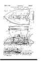
- Figure 1 is a top plan view of an electric laundry iron embodying this invention, lwith the hand piece of the handle member removed.
- Figure 2 is a section at the line 2-2 on Figure 1.
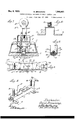
- Figure 3 is a fragmentary view consisting of a part of Figure 2 showing the parts of a thermostatic regulating device in diierent position from that shown in Figure 2.
- Figure 4 is a plan viewwith the handle and cover or enclosing shell and the heat storing member removed, and the upper sheath of the heating unit partly broken away to show the heating coils.
- Figure 5 is a plan view with the handle and enclosing shell removed, and the heat storing member partly broken away to show the heating unit below it.
- Figure 6 is a section at the line 6-6 on Figure 2, with the handle upright partly broken away to reduce the view.
- Figure 7 is a section at the line 7--7 on Figure 2.
- Figure 8 is a bottom plan view of the handle and certain adjustable parts carried on the handle strap.
- Figure 9 1s a perspective view of a frame which is mounted on the sole plate for varylng .the thermostatic governing device.
- Figure 10 is a section at the plane indicated by the line 10--10 on Figure 9 on an enlarged scale.
- Figure 11 is a section at the line 11-11' on Figure 5, on an enlarged scale.
- -A isthe sole plate,-the bottom member of the body of the iron having the working face.
- D is the heating unit mounted uponlthe upper side of tl sole plate.
- C is a heat storage member mounted above the heating unit and serving to hold the latter tightly upon the upper surface ofk the sole plate.
- J is a cover or enclosing shell hereinafter referred toas the cover shell.
- E is the handle comprisin .a hand piece, E1, and a handle strap, E2, at the upper end of which the hand piece is carried.
- F1 and F2 are the plug-en aging circuit terminal pins; f1 and f2 are exible metal strips constituting initial arts of the circuit connections from the pins, F1 and F2, respectively,
- a frame, G mounted upon the sole plate, overhanging the recess, a, of the latterand extending up into the recess, e, of the storage member.
- This frame, G comprises upright lateral webs, 10 extending uninterruptedly over the entire length of the frame, and connected at their upper edges by transverse webs, 11, 11,
- the frame G is mounted on the sole plate by means of laterally projecting lugs. 12 ⁇ 12, provided at the lower edges of the upright webs. 10 ⁇ 10, the sole plate having in its upper surface recesses, 12, in which the lugs 12. are seated, and at which they are secured to the sole plate by screws, 13, 13, screwed through said lugs into the sole plate.
- This ⁇ frame. G is conveniently arranged for carrying the plug socket, F, as may be understood from Figure 2.
- thermostatic devices for controlling the operation for maintaining the iron at predetermined temperature will now be described.
- thermostat bi-metallic bar
- H hereinafter referred to as a thermostat
- said thermostat being rigidly, but adjustably, secured at one end insulatedly to the sole plate by means of a mountingV fitting consisting of a U-shaped stamping, 17, having parallel limbs, 17, 17", extending inside the upright side webs, 10.
- said fitting having an arm, 17, extended from the cross web of its U-form, said arm at a short distance from said cross web being bent first upwardly and then to the right, as seen in Figure 2, and having its extremity secured to the sole plate by being fastened by a screw, 17d to the top of a post, 17, which is screwed into the sole plate and adapted to be adjusted vertically by screwing it more or less into the sole plate, for which purpose it has a hexagonal head, 17.
- the thermostat, H is secured insulatedly to the fitting, 17, by bolts, 19, 19 which also secure insulatedly to the fitting and conductively to the thermostat a conductive bracket, 20, which is provided for connecting the thermostat conductively with the heating coil, said connection being effected by the fiexible conductor, f, above mentioned, leading from the coil and secured to the bracket 20, by a binding screw, as seen at 21.
- the thermostat, H is insulated from the U-shaped fitting, 17, by means of a mica strip. 25, interposed between said fitting and the thermostat, as seen in Fi re 11.
- the bracket, 20 is insulated from the fitting, 17. by a mica strip, 24, as seen in Figure 11, and the cross web of the U-form of the fitting, 17 has the apertures through which the bolts, 19, 19 extend enlarged for ample clearance around the bolts, so that the latter do not effect electrical conduction from the bracket, 20, to said fitting, 17.
- the mica strip. 24, is extended along the entire length of the thermostat, and the thermostat carries at its free end a contact button, 30, at the end of a spring arm, 31; made fast at the other end to the free end of the thermostat.
- the purpose of this spring mounting for the contact button will be hereinafter explained.
- a cooperating contact carrier, 40 for cooperating with the thermostat in the regulation of the temperature of the iron, there is provided a cooperating contact carrier, 40, ivotally mounted at one end in the frame, on the pivot pin, 17 said contact being carried at the end of a conducting strip, 42, mounted insulatedly on the contact carrier, said insulation being effected by a mica strip, 48, interposed between the contact carrier, 40, and the conducting strip, 42, the conducting strip being secured to the contact carrier by rivets, 44, 44, insulated from the carrier, as indicated by insulations consisting of mica washers, 45, interposed under the rivet heads, as seen in Fi res 2 and 3.
- the conducting strip, 42 which carries the contact, 42, is connected in circuit with the heating coil by means of .a flexible conductor shown at f, which is clamped at one end between the insulating mica strip, 43, and the conducting strip, 42, and connected at the other end to circuit terminal pin, F2, as seen in Figure 7.
- a bell crank lever, 50 For holding the co-operating contact carrier, 40, in definite position, and for adjusting it to vary the temperature limit at which the circuit is interrupted, there is provided a bell crank lever, 50, fulcrumed at its angle on a fulcrum pin, 49, mounted in op ositely positioned lugs, 53, 53, projecting up rom the upper edges of the webs, 10, 10, of the frame, G, said lever having a relatively short arm, 51, extending between the webs, 10, 10, of the frame, G, longitudinally of said frame, reflexed u on itself to form a slot, 51, and er.- gaging 1n said slot is a pin, 55, mounted in upstanding lugs, 56, 56, which are folded up from the opposite ed es of the cooperating contact carrier, 40, t e upstanding arm of the bell crank lever being extended up through an aperture, 57, in the heat storage member, C, and arranged at its up r end for actuation by
- the contact button, 42 is at such position that the thermostat in its normally iexed form holds the contact button, 30, in contact with the contact button, 42, with the springarm, 31,' flexed as seen in Figure 2 and reacting resiliently for stressing the contact button, 80, against the contact button, 42a.
- the circuit when the iron is in use so as to utilize the heat by radiation or conduction, the circuit will remain closed as long as the utilized heat substantially equals the heat generated by the heating unit; and that when the circuit 1s interrupted in the manner described by the momentary rise of the temperature beyond the predetermined degree, if the conditions of use are such as to cause continued radiation of the heat, causing the iron to become cooled below the limit, the circuit will be immediately closed, and if the heat generating capacity of the heating unit is substantially equal to the capacity of the iron for giving oi heat by conduction or radiation, there will result a rapid succession of openings and closii gs of the circuit, with the practical eiect of a continually closed circuit, with unappreciable variation of the temperature, causing the generation of the precise amount of heat utilized by loss of radiation from the iron.
- Figure 3 sh ws the contacts, 30 and 42, and the thermostat at substantially straight position which may be understood to be the positionand form of the thermostat at the maximum temperature.
- This figure may be understood as intended to show the adjusting devices set for holding the cooperating contact carrier atposition for medium temperature. And from this showing it may be understood that the iron has been operating at high temperature and the operator has adjusted the adjusting devicesv to the low or lower temperature, as medium, thereby causing thecontacts to be Separated; and that they will remain thus separated until the thermostat cools down approximately to the temperature for which the adjustment is made, this cooling causing the thermostat to become flexed for carrying the contact button, 30, up into Contact again with the contact but-ton, 42a, causing the circuit to be closed and the heating unit energized for maintaining that temperature.
- the spring stem, 3l, of the contact, 30, at the cold condition must be reacting resiliently for stressing the contact, 30, against the contact, 42a, to an extent requiring the straightening of the thermostat enough to offset and compensate that resilient reaction, by rise of temperature to said lowest temperature limit at which the iron is to be operated; and that the structure may operate in this manner is the purpose of the spring stem, 3l, of the contact, 30.
- the principle of operation of the thermostat requires that it should be iixedly held at one end so that the change of form due to change of temperature shall cause the movement of the free end at which the contact is carried to be definite and. to correspond always to 'the temperature change, as could not be depended upon to be the case if the other end could perform part o the movement.
- the temperature at which the contacts will separate depends, to a considerable extent, on the range of the resilient action of the spring stem, 31,01? the contact, 30, and the extent to which it is flexed or straightened from the normal form at the normal position of the parts as assembled at normal atmospheric temperature.
- the thermostat is mounted as described, so that it is adjustable at its rigidly secured end by setting the threaded post, 17, more or less deeply into the sole plate.
- v v The manually operable ad'ustingzdevices for-l setting the thennostatic evioes to vary the redetermined temperature limit will now be escribed: v v
- These adjusting devices comprise a slide, 60, on the horizontal portion of the handle strap, said slide being mounted upon the u per side of said handle strap and having c as ing lugs, 61, enga 'ng the lateral ed of the' strap as seen 1n igure 2.
- This slide has a ran of movement on the handle strap between t e posts which secure it to the body of the iron', as hereinafter more particulary described, and within the range of said sli in movement the handle strap has markings indicating several degrees of temperature'for which .the device may be adjusted, said markings consisting, as seen in Figurel, in the words Hi h, Med. indicating medium) and Low and the sli e has a reading slot, 70, through which these markings may be read at the positions respectively of the slide corresponding to the temperature indicated.
- the slide carries an operating stem, 63, which ismounted in a bearing, 62, formed at the center of an up-struck hollow boss, 62, of
- Said stem extends down through a .lon 'tudinal slot, 68, in the handle stra and t rough a correspondingly positione slot, 82, in the cover shell, J, and engages at its lower end the upper end of the upstanding arm of the bell crank, 50, as seen in Figure 2 and heretofore mentioned.
- the operatin stem, 63,- is provided at its upper end witlgx an operatingk-nob, 64, which is itself journaled on the bearlng, 62, for assisting in holding the operating stem accurately in the vertical position.
- the operating stem carries rigid with it under the hollow boss, 62, a disk, 65, having a rigidly projecting pin, 66, which-engages a short transverse slot, 67, in the handle stra opposite the middle point of the length o the slot, 68, in which the operating stem, 63, moves for operating the bell crank lever, 50.
- the pin, 66 upon rotating the handle, 64, the pin, 66, becomes a fulcrum about ywhich said disk swings as it is located by the handle, the pin, 66, moving in the transverse slot a distance corresponding to thel height of the segment de fined by the arc of movement of the pin about the center of its rotative movement, viz., the operating stem, 62; and that accordingly with only an amount of movement of the pin tranaversel of the handle strap equal to the hei ht of t at segment, there il obtained longitu inal sliding movement of the slide, 60, equal to the chord of the arc of said se ment, which is suicient for shifting the sli e through the entire range of movement necessary Y or operating the bell crank lever, 50, to eil'ect the maximum adjustment necessary and to shift the slot, 70, from High to Lew ition of the temperature markings on the e'strap.
- An electric laundry iron having in combination with a heating unit and a sole late on which the heating unit is mounte for heating the plate, the sole plate having a recess in its upperside at a portion of its area which is not occupied by the heating unit; a thermostatic bar positioned lin said means for securin it rigidly at one and with the other end for movement due to changes f'forms of the bar upon chan of temperature; a circuit-making-and-brea g contact carried by the bar at its free end; a pivoted contact carrier, and a co-o rating contact carried thereb remotely om the pivot and positioned or meeting the first mentioned contact yin the pivotal movement of said co-ope ting contact carrier, one of said contactsbeing resiliently mounted on the part which carnes it, and a frame mounted on the sole plate over the recess therein and extendin up above the level of the upr surface of the sole plate, the thermostatic ar and the co-operat'mg contact carrier be-v inxboth mounted in the manners respectively
- An electric laundry iron having in combination withf a heating unit and a sole late on which the heating unit is mounte for ⁇ heating the plate, the sole plate having a recess in its upper side at a portion of its area which is not occupied by the heating unit; a thermostatic bar positioned in said recess, means for securing it rigidly at one end with the other end free for movement due to changes of forms.
- An electric laundry iron having in combination with a heating unit and a sole late on which the heating unit is mounte for heating the plate, a heat storage member lodged above the heating unit, the sole plate having a recess in its upper side and the heat storage member having a recess in its lower side registering with the recess of the sole plate, a frame structure mounted on the sole plate and extendin eat storage mem r, a thermostatic bar mounted on the frame and positioned thereby in the recess of the sole plate, a contact carried by the thermostatic bar, a co-o erating contact carrier adjustably mounte on the frame, and a contact carried thereby positioned for co-operating with the contact carried by the thermostatic bar, said co-o erating contact carrier being carried by the rame substantially entirely in the recess of the heat storage member at normal position of the parts at a predetermined temperature of the thermostatlc bar, connections :for ad'usting the co-operating contact carrier exten ing up through the .heat
Landscapes
- Irons (AREA)
Description
G. BRowNlNG 1,908,401
THERMOSTATICALLY GOVERNED ELECTRIC LAUNDRY IRON May 9, 1933.
Original Filed June 17. 1929 3 Sheets-Sheet l ,Z/e 72 ZLoZ/f efozma/y. M m @zzz g5 G. BROWNING May 9, 1933.
WYERMOSTATICALLY GOVERNED ELECTRIC LAUNDRY IRON Original Filed June 17, 1929 3 Sheets-Sheet 2 j ff May 9, 1933.
THERMosTATIcALLY GovERNED ELECTRIC LAUNDRY IRON G. BRowNlNG 1,908,401
5 Sheets-Sheet 3 Original Filed June 1'7, 1929 Patented May 9, 1933 UNITED sTATEs,
PATENT OFFICE GEORGE BROWNING, OF WILMETTE, ILLINOIS, ASSIGNOB TO CHICAGO FLEXIBLE SHAFI' COMPANY, OF CHICAGO, ILLINOIS, A CORPORATION OF ILLINOIS i TBEBHOSTATICALLY GOVERNED ELECTRIC LAUNDRY IRON Original `application med June 1 7, 1929, Serial No. 871,356. Divided and this application iiled April 5,
1900. Serial This ap lication is a division of my application erial No. 371,356, filed June 17, 1929, now Patent No. 1,779,960, issued Oct. 28,1930.
The purpose of this invention is to provide an improved construction of an electric laundry iron having thermostatic devices for automatically governing the temperature of the iron by automatically interrupting the circuit by which it is energized when any predetermined temperature is obtained, and automatically restoring the circuit connection when the temperature falls below such predetermined degree, with manually accessible and operable means for adjusting the thermostatic devices to vary at will a predetermined degree of temperature at which the circuit is interrupted and restored. It consists in the elements and features of con struction shown and described as indicated in the claims.
In the drawings Figure 1 is a top plan view of an electric laundry iron embodying this invention, lwith the hand piece of the handle member removed.
Figure 2 is a section at the line 2-2 on Figure 1.
Figure 3 is a fragmentary view consisting of a part of Figure 2 showing the parts of a thermostatic regulating device in diierent position from that shown in Figure 2.
Figure 4 is a plan viewwith the handle and cover or enclosing shell and the heat storing member removed, and the upper sheath of the heating unit partly broken away to show the heating coils. l
Figure 5 is a plan view with the handle and enclosing shell removed, and the heat storing member partly broken away to show the heating unit below it.
Figure 6 is a section at the line 6-6 on Figure 2, with the handle upright partly broken away to reduce the view. v
Figure 7 is a section at the line 7--7 on Figure 2. l
, Figure 8 is a bottom plan view of the handle and certain adjustable parts carried on the handle strap.
Figure 9 1s a perspective view of a frame which is mounted on the sole plate for varylng .the thermostatic governing device.
Figure 10 is a section at the plane indicated by the line 10--10 on Figure 9 on an enlarged scale.
Figure 11 is a section at the line 11-11' on Figure 5, on an enlarged scale.
Referring to the drawings: -A isthe sole plate,-the bottom member of the body of the iron having the working face. D is the heating unit mounted uponlthe upper side of tl sole plate. C is a heat storage member mounted above the heating unit and serving to hold the latter tightly upon the upper surface ofk the sole plate. J is a cover or enclosing shell hereinafter referred toas the cover shell. E is the handle comprisin .a hand piece, E1, and a handle strap, E2, at the upper end of which the hand piece is carried. A socket for holding a plug not shown) carrying the, circuit wires not shown) leading to and from the source of current (not shown), is seen at F. F1 and F2 are the plug-en aging circuit terminal pins; f1 and f2 are exible metal strips constituting initial arts of the circuit connections from the pins, F1 and F2, respectively,
'to the heating coils, D1, in the heating unit, D,
laterally .than the latter. For mounting the thermostatic regulating devices in the recesses, a and c, there is provided a frame, G, mounted upon the sole plate, overhanging the recess, a, of the latterand extending up into the recess, e, of the storage member. This frame, G, comprises upright lateral webs, 10 extending uninterruptedly over the entire length of the frame, and connected at their upper edges by transverse webs, 11, 11,
aving uprights, e2,
each extending for a short portion only of the length ofr` the frame, leaving between them suitably extended openings for connections, hereinafter described. which are provided for adjusting thc thermostatic legulating devices. The frame G, is mounted on the sole plate by means of laterally projecting lugs. 12` 12, provided at the lower edges of the upright webs. 10` 10, the sole plate having in its upper surface recesses, 12, in which the lugs 12. are seated, and at which they are secured to the sole plate by screws, 13, 13, screwed through said lugs into the sole plate. This` frame. G, is conveniently arranged for carrying the plug socket, F, as may be understood from Figure 2.
The thermostatic devices for controlling the operation for maintaining the iron at predetermined temperature will now be described.
These devices comprise a bi-metallic bar, H. hereinafter referred to as a thermostat, said thermostat being rigidly, but adjustably, secured at one end insulatedly to the sole plate by means of a mountingV fitting consisting of a U-shaped stamping, 17, having parallel limbs, 17, 17", extending inside the upright side webs, 10. 10, of the frame, G, and pivoted thereto as seen at 17 b, said fitting having an arm, 17, extended from the cross web of its U-form, said arm at a short distance from said cross web being bent first upwardly and then to the right, as seen in Figure 2, and having its extremity secured to the sole plate by being fastened by a screw, 17d to the top of a post, 17, which is screwed into the sole plate and adapted to be adjusted vertically by screwing it more or less into the sole plate, for which purpose it has a hexagonal head, 17. The thermostat, H, is secured insulatedly to the fitting, 17, by bolts, 19, 19 which also secure insulatedly to the fitting and conductively to the thermostat a conductive bracket, 20, which is provided for connecting the thermostat conductively with the heating coil, said connection being effected by the fiexible conductor, f, above mentioned, leading from the coil and secured to the bracket 20, by a binding screw, as seen at 21.
The thermostat, H, is insulated from the U-shaped fitting, 17, by means of a mica strip. 25, interposed between said fitting and the thermostat, as seen in Fi re 11. The bracket, 20 is insulated from the fitting, 17. by a mica strip, 24, as seen in Figure 11, and the cross web of the U-form of the fitting, 17 has the apertures through which the bolts, 19, 19 extend enlarged for ample clearance around the bolts, so that the latter do not effect electrical conduction from the bracket, 20, to said fitting, 17.
And the bolts, 19, having their heads binding the under side of the thermostat and their nuts, 19, clamping a washer plate, 26,
onto the upper side of the horizontal arm of the bracket, 20, constitute efective conductors for the current from the bracket, 20, to the thermostat.
The mica strip. 24, is extended along the entire length of the thermostat, and the thermostat carries at its free end a contact button, 30, at the end of a spring arm, 31; made fast at the other end to the free end of the thermostat. The purpose of this spring mounting for the contact button will be hereinafter explained.
For cooperating with the thermostat in the regulation of the temperature of the iron, there is provided a cooperating contact carrier, 40, ivotally mounted at one end in the frame, on the pivot pin, 17 said contact being carried at the end of a conducting strip, 42, mounted insulatedly on the contact carrier, said insulation being effected by a mica strip, 48, interposed between the contact carrier, 40, and the conducting strip, 42, the conducting strip being secured to the contact carrier by rivets, 44, 44, insulated from the carrier, as indicated by insulations consisting of mica washers, 45, interposed under the rivet heads, as seen in Fi res 2 and 3. The conducting strip, 42, which carries the contact, 42, is connected in circuit with the heating coil by means of .a flexible conductor shown at f, which is clamped at one end between the insulating mica strip, 43, and the conducting strip, 42, and connected at the other end to circuit terminal pin, F2, as seen in Figure 7.
For holding the co-operating contact carrier, 40, in definite position, and for adjusting it to vary the temperature limit at which the circuit is interrupted, there is provided a bell crank lever, 50, fulcrumed at its angle on a fulcrum pin, 49, mounted in op ositely positioned lugs, 53, 53, projecting up rom the upper edges of the webs, 10, 10, of the frame, G, said lever having a relatively short arm, 51, extending between the webs, 10, 10, of the frame, G, longitudinally of said frame, reflexed u on itself to form a slot, 51, and er.- gaging 1n said slot is a pin, 55, mounted in upstanding lugs, 56, 56, which are folded up from the opposite ed es of the cooperating contact carrier, 40, t e upstanding arm of the bell crank lever being extended up through an aperture, 57, in the heat storage member, C, and arranged at its up r end for actuation by a manually operate device which is mounted upon the handle strap, E2, and projects down through said strap and through the cover shell, J, for engaging said bell crank lever, as will be hereinafter more particularly described.
U on considering the construction as thus far ascribed and 1s shown in the drawings, it may be understood that at normal atmospheric temperature which may be hereinafter referred to as cold the thermostat, H, is
eonsidrably flexed from straight position, substantially as seen in Figure 2, and is adapted to become straight as seen in Figure 3 when heated to the predetermined temperature limit at which the circuit is to be interrupted for preventing further rise in temperature. And it will be understood that at the position corresponding to cold temperature of the iron, and at any position to which the cooperating contact button, 30, is intended to be adjusted, the contact button, 42, is at such position that the thermostat in its normally iexed form holds the contact button, 30, in contact with the contact button, 42, with the springarm, 31,' flexed as seen in Figure 2 and reacting resiliently for stressing the contact button, 80, against the contact button, 42a. And it will be recognized, therefore, that the two contact buttons will remain in contact, keeping the circuit closed and the heating unit energized until the thermostat becomes heated to a degree at which it will be straightened enough to take up the resilient action of the spring stem, 31, of the contact butt-on, 30 and that upon becoming heated beyond this point and further straightened it will withdraw the Contact button, 30, from the contact button, 42a, and cause the circuit to be interrupted. And it will be recognized that upon this interruption and the cooling of the ironk and the. thermostat which will follow upon the thermostat becoming slightly cooled will again carry the Contact button, 30, into contact with the button, 42a, closing the circuit connection and continuing the heating and maintaining the temperature ofthe irony to the maximum for which the adjustment is made. The result is that when the iron is in use so as to utilize the heat by radiation or conduction, the circuit will remain closed as long as the utilized heat substantially equals the heat generated by the heating unit; and that when the circuit 1s interrupted in the manner described by the momentary rise of the temperature beyond the predetermined degree, if the conditions of use are such as to cause continued radiation of the heat, causing the iron to become cooled below the limit, the circuit will be immediately closed, and if the heat generating capacity of the heating unit is substantially equal to the capacity of the iron for giving oi heat by conduction or radiation, there will result a rapid succession of openings and closii gs of the circuit, with the practical eiect of a continually closed circuit, with unappreciable variation of the temperature, causing the generation of the precise amount of heat utilized by loss of radiation from the iron.
Figure 3 sh ws the contacts, 30 and 42, and the thermostat at substantially straight position which may be understood to be the positionand form of the thermostat at the maximum temperature. This figure may be understood as intended to show the adjusting devices set for holding the cooperating contact carrier atposition for medium temperature. And from this showing it may be understood that the iron has been operating at high temperature and the operator has adjusted the adjusting devicesv to the low or lower temperature, as medium, thereby causing thecontacts to be Separated; and that they will remain thus separated until the thermostat cools down approximately to the temperature for which the adjustment is made, this cooling causing the thermostat to become flexed for carrying the contact button, 30, up into Contact again with the contact but-ton, 42a, causing the circuit to be closed and the heating unit energized for maintaining that temperature.
It ma;7 be understood from the foregoing description that for the ordinary purposes of a laundry iron the adjusting devices will be arranged so that at the adjustment for the lowest temperature at which thel iron is to be operated the circuit will be closed-that is, the buttons will be in contact-when the iron is cold, so that when the iron is connected by the plug in the usual manner with the source of current, it will begin to warm up immediately, which could not happen unless the circuit in the iron itself were closed. And in order that the circuit shall not be immediately opened by change of form of the thermostat, the spring stem, 3l, of the contact, 30, at the cold condition must be reacting resiliently for stressing the contact, 30, against the contact, 42a, to an extent requiring the straightening of the thermostat enough to offset and compensate that resilient reaction, by rise of temperature to said lowest temperature limit at which the iron is to be operated; and that the structure may operate in this manner is the purpose of the spring stem, 3l, of the contact, 30.
Upon careful consideration of the structure it may be recognized that the principle of operation of the thermostat requires that it should be iixedly held at one end so that the change of form due to change of temperature shall cause the movement of the free end at which the contact is carried to be definite and. to correspond always to 'the temperature change, as could not be depended upon to be the case if the other end could perform part o the movement. And it will be recognized also that the temperature at which the contacts will separate depends, to a considerable extent, on the range of the resilient action of the spring stem, 31,01? the contact, 30, and the extent to which it is flexed or straightened from the normal form at the normal position of the parts as assembled at normal atmospheric temperature. And it will be recognized that the slight and unavoidable variations in the stiffness of the spring stem and in its normal form, as being straight or slightly curved, will make it extremely dif-v cult to ensure uniformity in diil'erent irons even of the same lot, in respect to the temperature limit at which the contacts will separate at any given adjustment of the cooperating contact carrier, as at high or low.` It is in view of these considerations that the thermostat is mounted as described, so that it is adjustable at its rigidly secured end by setting the threaded post, 17, more or less deeply into the sole plate.
The manually operable ad'ustingzdevices for-l setting the thennostatic evioes to vary the redetermined temperature limit will now be escribed: v v These adjusting devices comprise a slide, 60, on the horizontal portion of the handle strap, said slide being mounted upon the u per side of said handle strap and having c as ing lugs, 61, enga 'ng the lateral ed of the' strap as seen 1n igure 2. This slide has a ran of movement on the handle strap between t e posts which secure it to the body of the iron', as hereinafter more particulary described, and within the range of said sli in movement the handle strap has markings indicating several degrees of temperature'for which .the device may be adjusted, said markings consisting, as seen in Figurel, in the words Hi h, Med. indicating medium) and Low and the sli e has a reading slot, 70, through which these markings may be read at the positions respectively of the slide corresponding to the temperature indicated. The slide carries an operating stem, 63, which ismounted in a bearing, 62, formed at the center of an up-struck hollow boss, 62, of
the slide.A Said stem extends down through a .lon 'tudinal slot, 68, in the handle stra and t rough a correspondingly positione slot, 82, in the cover shell, J, and engages at its lower end the upper end of the upstanding arm of the bell crank, 50, as seen in Figure 2 and heretofore mentioned. The operatin stem, 63,-is provided at its upper end witlgx an operatingk-nob, 64, which is itself journaled on the bearlng, 62, for assisting in holding the operating stem accurately in the vertical position. The operating stem carries rigid with it under the hollow boss, 62, a disk, 65, having a rigidly projecting pin, 66, which-engages a short transverse slot, 67, in the handle stra opposite the middle point of the length o the slot, 68, in which the operating stem, 63, moves for operating the bell crank lever, 50. Upon considering this construction it will be understood that upon rotating the handle, 64, the pin, 66, becomes a fulcrum about ywhich said disk swings as it is located by the handle, the pin, 66, moving in the transverse slot a distance corresponding to thel height of the segment de fined by the arc of movement of the pin about the center of its rotative movement, viz., the operating stem, 62; and that accordingly with only an amount of movement of the pin tranaversel of the handle strap equal to the hei ht of t at segment, there il obtained longitu inal sliding movement of the slide, 60, equal to the chord of the arc of said se ment, which is suicient for shifting the sli e through the entire range of movement necessary Y or operating the bell crank lever, 50, to eil'ect the maximum adjustment necessary and to shift the slot, 70, from High to Lew ition of the temperature markings on the e'strap.
I claim:
1. An electric laundry iron having in combination with a heating unit and a sole late on which the heating unit is mounte for heating the plate, the sole plate having a recess in its upperside at a portion of its area which is not occupied by the heating unit; a thermostatic bar positioned lin said means for securin it rigidly at one and with the other end for movement due to changes f'forms of the bar upon chan of temperature; a circuit-making-and-brea g contact carried by the bar at its free end; a pivoted contact carrier, and a co-o rating contact carried thereb remotely om the pivot and positioned or meeting the first mentioned contact yin the pivotal movement of said co-ope ting contact carrier, one of said contactsbeing resiliently mounted on the part which carnes it, and a frame mounted on the sole plate over the recess therein and extendin up above the level of the upr surface of the sole plate, the thermostatic ar and the co-operat'mg contact carrier be-v inxboth mounted in the manners respectively 1n 'cated on said frame with the co-operating contact carrier above the upper surface of the sole'plate and above the level of the heating unit.
2. An electric laundry iron having in combination withf a heating unit and a sole late on which the heating unit is mounte for `heating the plate, the sole plate having a recess in its upper side at a portion of its area which is not occupied by the heating unit; a thermostatic bar positioned in said recess, means for securing it rigidly at one end with the other end free for movement due to changes of forms. of the bar upon chan e of temperature; a circuit-making-and-brea 'ng contact carried by the bar at its free end; a pivoted contact carrier, and a co-operating contact carried thereby remotely from the pivot and positioned for meeting the first mentioned contact in the pivotal movement of said co-operating contact carrier; a resilient stem by which the first mentioned contact 1s mounted at the free end of the thermostatic bar, and a frame mounted on the sole plate over the recessV therein and extending up y'above the level of the upper surface of the sole plate, the thermostatlc bar and the co-operating contact carrier being both lll lll
mounted in the manners respectively indicated on said frame with the co-operating contact carrier above the upper surface of the sole plate and above the level of the heating unit. l
3. An electric laundry iron having in combination with a heating unit and a sole late on which the heating unit is mounte for heating the plate, a heat storage member lodged above the heating unit, the sole plate having a recess in its upper side and the heat storage member having a recess in its lower side registering with the recess of the sole plate, a frame structure mounted on the sole plate and extendin eat storage mem r, a thermostatic bar mounted on the frame and positioned thereby in the recess of the sole plate, a contact carried by the thermostatic bar, a co-o erating contact carrier adjustably mounte on the frame, and a contact carried thereby positioned for co-operating with the contact carried by the thermostatic bar, said co-o erating contact carrier being carried by the rame substantially entirely in the recess of the heat storage member at normal position of the parts at a predetermined temperature of the thermostatlc bar, connections :for ad'usting the co-operating contact carrier exten ing up through the .heat stora e member, an operating handle for the iron and mounting means for the same extended up from the said frame through the heat storage member, and manually accessible and operable means for operating the co-operating contact-car rier-adjusting connections mounted on the handle.
In testimony whereof, I have hereunto set m hand at Chicago, Illinois, this third day o April, 1930.
' GEORGE BROWNING.
into the recess of the
Priority Applications (1)
| Application Number | Priority Date | Filing Date | Title |
|---|---|---|---|
| US441742A US1908401A (en) | 1929-06-17 | 1930-04-05 | Thermostatically governed electric laundry iron |
Applications Claiming Priority (2)
| Application Number | Priority Date | Filing Date | Title |
|---|---|---|---|
| US371356A US1779960A (en) | 1929-06-17 | 1929-06-17 | Thermostatically-governed electric laundry iron |
| US441742A US1908401A (en) | 1929-06-17 | 1930-04-05 | Thermostatically governed electric laundry iron |
Publications (1)
| Publication Number | Publication Date |
|---|---|
| US1908401A true US1908401A (en) | 1933-05-09 |
Family
ID=27005346
Family Applications (1)
| Application Number | Title | Priority Date | Filing Date |
|---|---|---|---|
| US441742A Expired - Lifetime US1908401A (en) | 1929-06-17 | 1930-04-05 | Thermostatically governed electric laundry iron |
Country Status (1)
| Country | Link |
|---|---|
| US (1) | US1908401A (en) |
Cited By (3)
| Publication number | Priority date | Publication date | Assignee | Title |
|---|---|---|---|---|
| USD389622S (en) | 1996-12-04 | 1998-01-20 | Sunbeam Products, Inc. | Steam iron |
| USD389969S (en) | 1996-12-04 | 1998-01-27 | Sunbeam Products, Inc. | Dry iron |
| US20100257761A1 (en) * | 2009-04-08 | 2010-10-14 | Lung Wai Choi | Electric iron with a synchronizing temperature display |
-
1930
- 1930-04-05 US US441742A patent/US1908401A/en not_active Expired - Lifetime
Cited By (3)
| Publication number | Priority date | Publication date | Assignee | Title |
|---|---|---|---|---|
| USD389622S (en) | 1996-12-04 | 1998-01-20 | Sunbeam Products, Inc. | Steam iron |
| USD389969S (en) | 1996-12-04 | 1998-01-27 | Sunbeam Products, Inc. | Dry iron |
| US20100257761A1 (en) * | 2009-04-08 | 2010-10-14 | Lung Wai Choi | Electric iron with a synchronizing temperature display |
Similar Documents
| Publication | Publication Date | Title |
|---|---|---|
| US2008163A (en) | Thermostatic switch | |
| US1908401A (en) | Thermostatically governed electric laundry iron | |
| US2403115A (en) | Electric sadiron | |
| US1781244A (en) | Hair-curling machine | |
| US2658121A (en) | Condition responsive electric switch mechanism | |
| US2723336A (en) | Thermostatically controlled electric flatiron or the like | |
| US2681521A (en) | Thermostatically controlled electric flatiron or the like | |
| US1779960A (en) | Thermostatically-governed electric laundry iron | |
| US2824193A (en) | Thermostat apparatus | |
| US2201115A (en) | Automatic flatiron, and thermostatic device for controlling the same | |
| US1812845A (en) | Electroresponsively controlled mechanism | |
| US2146992A (en) | Thermostatically controlled electrically heated iron | |
| US2195002A (en) | Sadiron | |
| US2048614A (en) | Flatiron thermostat | |
| US2307052A (en) | Circuit control for electric flatirons and connection therefor | |
| US2128807A (en) | Temperature control device | |
| US1977393A (en) | Temperature control device | |
| US2235893A (en) | Thermostat | |
| US2528254A (en) | Thermal cutout for flatirons or the like | |
| US2546471A (en) | Thermostatic switch | |
| US1684281A (en) | Temperature regulator for electric heaters | |
| US1742558A (en) | Electric heater | |
| US2230713A (en) | Circuit breaker | |
| US2102892A (en) | Electric flatiron | |
| US2640130A (en) | Thermostat |