US1908391A - Shock absorber - Google Patents
Shock absorber Download PDFInfo
- Publication number
- US1908391A US1908391A US267038A US26703828A US1908391A US 1908391 A US1908391 A US 1908391A US 267038 A US267038 A US 267038A US 26703828 A US26703828 A US 26703828A US 1908391 A US1908391 A US 1908391A
- Authority
- US
- United States
- Prior art keywords
- piston
- cylinder
- spring
- movement
- pin
- Prior art date
- Legal status (The legal status is an assumption and is not a legal conclusion. Google has not performed a legal analysis and makes no representation as to the accuracy of the status listed.)
- Expired - Lifetime
Links
- 230000035939 shock Effects 0.000 title description 33
- 239000006096 absorbing agent Substances 0.000 title description 22
- 239000012530 fluid Substances 0.000 description 33
- 230000006835 compression Effects 0.000 description 9
- 238000007906 compression Methods 0.000 description 9
- 230000000979 retarding effect Effects 0.000 description 8
- 230000009471 action Effects 0.000 description 6
- 239000007788 liquid Substances 0.000 description 5
- 101150009194 cap4 gene Proteins 0.000 description 2
- 238000010276 construction Methods 0.000 description 2
- 230000000694 effects Effects 0.000 description 2
- 238000009434 installation Methods 0.000 description 2
- 230000007246 mechanism Effects 0.000 description 2
- 230000003068 static effect Effects 0.000 description 2
- 241000239290 Araneae Species 0.000 description 1
- 206010026749 Mania Diseases 0.000 description 1
- 235000014676 Phragmites communis Nutrition 0.000 description 1
- 208000036366 Sensation of pressure Diseases 0.000 description 1
- 238000013019 agitation Methods 0.000 description 1
- 238000013459 approach Methods 0.000 description 1
- 230000008878 coupling Effects 0.000 description 1
- 238000010168 coupling process Methods 0.000 description 1
- 238000005859 coupling reaction Methods 0.000 description 1
- 238000010586 diagram Methods 0.000 description 1
- 238000006073 displacement reaction Methods 0.000 description 1
- 238000000034 method Methods 0.000 description 1
- 238000012986 modification Methods 0.000 description 1
- 230000004048 modification Effects 0.000 description 1
- 230000007935 neutral effect Effects 0.000 description 1
- 230000008569 process Effects 0.000 description 1
- 230000009467 reduction Effects 0.000 description 1
- 238000007789 sealing Methods 0.000 description 1
Images

Classifications
-
- F—MECHANICAL ENGINEERING; LIGHTING; HEATING; WEAPONS; BLASTING
- F16—ENGINEERING ELEMENTS AND UNITS; GENERAL MEASURES FOR PRODUCING AND MAINTAINING EFFECTIVE FUNCTIONING OF MACHINES OR INSTALLATIONS; THERMAL INSULATION IN GENERAL
- F16F—SPRINGS; SHOCK-ABSORBERS; MEANS FOR DAMPING VIBRATION
- F16F9/00—Springs, vibration-dampers, shock-absorbers, or similarly-constructed movement-dampers using a fluid or the equivalent as damping medium
- F16F9/10—Springs, vibration-dampers, shock-absorbers, or similarly-constructed movement-dampers using a fluid or the equivalent as damping medium using liquid only; using a fluid of which the nature is immaterial
- F16F9/14—Devices with one or more members, e.g. pistons, vanes, moving to and fro in chambers and using throttling effect
- F16F9/16—Devices with one or more members, e.g. pistons, vanes, moving to and fro in chambers and using throttling effect involving only straight-line movement of the effective parts
- F16F9/22—Devices with one or more members, e.g. pistons, vanes, moving to and fro in chambers and using throttling effect involving only straight-line movement of the effective parts with one or more cylinders each having a single working space closed by a piston or plunger
- F16F9/28—Devices with one or more members, e.g. pistons, vanes, moving to and fro in chambers and using throttling effect involving only straight-line movement of the effective parts with one or more cylinders each having a single working space closed by a piston or plunger with two parallel cylinders and with the two pistons or plungers connected together
Definitions
- This invention relatesto shock absorbers designed primarily for use in connection with motor vehicles, the principal object being to provide a shock absorber having a variable by-pass which will adjust itself automatically to theload and operate with equal efiiciency 1 under all load conditions.
- Another object of the invention is to provide a'shock absorber which will allow considerable variance, of installation from the proper position, such as will occur when inexperienced persons make the installation, without affecting its operation.
- a further object is to provide a shockabsorber having a center or zero point from which the device will work, this center or zero point being at all times in proper relation to the normal osition of the vehicle springs regardless o the weight carried by them or of any civilhat might develop in the springs 'due to weakness.
- a further object is to provide a shock absorber utilizing a port or by-pass' with which cooperates a metering in or valve of novel construction for 'contro ling the flow of fluid used in the shock absorber, thereby varying the flow and, correspondingly, the movement ofthe working parts of the device.
- Figure 3 is a bottom plan view of the piston.
- Figure 4 is a section on line 4 -4, Figure 2.
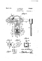
- Figure 5 is a view similar to Figure 1 showplan view of the upper end ing'a modified form of the device wherein two working units are combined for the purpose of exerting proper control over a vehicle spring both during the compression and the rebound thereof.
- Figure 6 is a view in diagram showing the- .action of the pin valve.
- FIG. 1 designates the body of the shock absorber casing, the same being formed with a recess 2 with which communicates the open end of a cylinder 3 extending from the body, 1
- a cap4 is adapted to be secured on the body 1 for the purpose of closing or sealing the if desire with a filling openin 5 normally closed by a screw plug 6 or the fire.
- a transverse shaft 7 is journalled in the body 1 and any suitable means, such as an arm 8 and a coupling rod 9 canbe utilized for connecting this shaft to the axle of a vehicle or any other suitable parts.
- the body 1 is adapted to be fastened to the chassis of the vehicle.
- crank arm 10 Secured to the'shaft 7 so as to move therewith is a crank arm 10 located within the recess 2 and connected by a link 11 or any other suitable means to an ear 12 which extends across one end of a hollow piston 13.
- This piston has a working'fit in the cylinder 3 and that end of the piston remote from the ear 12 is provided with segmental openings 14 separated by a spider 15 which, as shown 7 in Figures 1 and 4, is provided preferably with a central boss 16 interiorly screwthreaded.
- a tubular stem 17 Seated within the boss 16 is the threaded end of a tubular stem 17 which extends beyond the apertured end of the piston and is provided at its projecting end with an annular flange or collar 18.
- a disk valve 19 is slidable freely on the stem 17 and is held normally seated against the adjacent face of the piston 13 by a spring 20 which bears at one end against the .collar 18 and at its other end against the valve 19.
- the port or by-pass through the stem 17 is restricted where it is surrounded by the collar 18, this restricted portion providing opfiosed tapered faces as shown at 21.
- a load compensating piston 22 in one face of which is formed a concentric recess 23 providing a seat for one end of a spring 24. The other end of this spring bears against the closed end of the cylinder.
- a central concentric recess 25 is provided in that face of piston 22 nearest the piston 13 and in this recess is seated a shell 26 which constitutes a lining for the recess.
- This shell has an inturned flange 27 at its open end which laps and serves to limit the movement of an annular flange 28 formed at one end of a ca 29 having vent openings 29, ,The cap an shell obviously loosely engage each other.
- a coiled spring 30 is seated in the shell 26 and the cap 29' and thrusts against one end of the cap so as to hold it normally pressed against the flange or collar 18.
- This cap has an opening 31 which communicates with the restricted opening in the stem 17.
- a vent 35 is provided in the load com-.
- Spring 24 is adapted to yield under different loads.
- Spring 30 is stronger than spring 24 so that a thrust ordinarily transmitted therethrough to the piston 22 will produce a compression of the spring 24.. This spring 30, however, is adapted to yield slightly to permit movement piston 22 and provides a means past the zero point after the application of a load.
- the cylinder and the body are filled with a suitable fluid, such as oil, and after the body 1 has been attached to the chassis and the arm-8 has been anchored to the axle of the vehicle, the device is ready for use. Under normal conditions the reduced portion 34 of the pin 32 is located within the restriction-in the end of stem 17 When a load of any weight is applied to the vehicle so as to cause the chassis to move downwardly relative to the axle, a rotation of shaft 7 will be produced.
- a suitable fluid such as oil
- portion 33 of the pin approaches the restric-- tion 21 and nearly closes it so as to ositivelyclose the opening in the stem an stop the downward movement of the piston. Thereafter the vehicle springs return the parts to their natural ositions.
- piston 13 has much larger openings than compensating piston 22 throu h which liquid may flow, and is normally reed in either direction under much faster.
- a shock causes piston 13 to move-away from piston 22 which 1s forced veryslowly by (spring 24 as the vent may flow is very small. 4 "Therefore piston 13 returns to normal position before piston 22 has moved sufii- 137 and is provided with ciently to materially affect the zero point and the pressure of spring 30 then returns it to the original position.
- the cylinder and the body of this structure are filled with .oil or other suitable fluid.
- the ve-- locity of the escaping fluid is reduced and said oil is directedagainst'the underside of the ear 12 which acts as a deflector. This operation serves to mufile the noise and to reduce agitation of the oil.
- shock absorbing unit such as described can be used efliciently, it
- the body 36 has two cylinders 37 and 37 extending there-from and opening thereinto.
- the cylinder 37 corresponds with the cylinder 3 already described and-themecha nism therein is the same as that already described with reference to Figure- 1.
- This mechanism includes the piston 38 with its disk valve 39, tubular stem 40, valve supportmg spring 41, compensating piston 42 and load compensating spring 43.
- the pin valve 44 is also similar to the, one alreadydescribed and operates inthe same manner within the restriction 45 which normally extends around the reduced portion 46 of the pin valve.
- a crosshead 47 is connected at its center to the shaft 48 from which arm 49 extends and one end of the crosshead is connected by.
- crosshead is connected by a link 51 to the ear 52 at the open end of another piston 53.
- This last piston has a working fit in the cylinder a tubular stem 54 the free-end of which has or collar 55.
- a spring 56 is supported by this an annular flange flange and bears against a diskvalve 57 for the purpose of normally closing the adjacent end of the piston 53.
- This piston has a vent 61 similar to the vent 62 in the piston .42 and a pin valve
- a load compensatingpiston 58 is mounted in the cylinder and? thrusts througha spring 59 against a ring 60 held in any suitable manner withinthe' 11'5
- The-other end of the mally in the steni 54 is cylindrical as shown tion 69 the diameter of which is slightly less at 64 and has a head or enlargement at its free end as shown at 65 for engagement with one end of a coiled spring 66.
- the other end of this spring bears upon an inturned flange 67 carried by a cap 68 mounted in the piston 53 and normally bearing against one end thereof.
- That portion of the pin valve 63 between the two pistons is tapered toward the piston 58 except adjacent its point of attachment where it has a short cylindrical porthan the diameter of the passage within the stem 54.
- the parts within the cylinder 37 act 0 ositely to the parts within the cylinder 3 7.
- Variations in the load will cause adjustment the action of the spring 66 through the pin valve 63 and the piston 58 so as to maintain the two pistons at zero positions relative to each other.
- the chassis and axle are shifting relative to each other and the piston 38 is moving toward the piston 42 for absorbing shock
- the piston 53 will be moved away from piston 58 so as to cause Valve disk 57 to open.
- valve 57 will close while valve disk 59 is opening and the relative movement of the parts will be retarded by the entry of the tapered portion of the pin valve 63 into the stem 54.
- the mechanism in the'cylindor 37 operates to prevent the vehicle spring from being compressed beyond a predetermined position irrespective of the force of the shock to which the vehicle is subjected.
- valve pin Although a regularly tapered valve pin has been disclosed it is to be understood that various other shapes can be employed and means other than pins might be used for the purpose of getting a variable retardation for absorbing shocks.
- piston and cylinder herein used are to be understood as referring to any mechanical equivalents of the parts referred to.
- a shock absorber for vehicles including a cylinder for holding fluid, a yieldingly restrained load compensating piston therein, a pressurev piston in the cylinder for actuation I relative to the cylinder and load compensating piston by the relative movement of the chassis and axle of a vehicle, cooperating meanspn the pistons for variably retarding of the pistons through the flow of fluid past the pressure piston, during relative movement of the pistons away from normal or zero positions, and a. compression spring between the istons and connected to one'piston, means orcing the load compensating piston in contact with said spring, for maintaining the pistons normally in a predetermined or zero relation under any vehicle load.
- a shock absorber for vehicles including a cylinder for holding fluid, a yieldingly restrained load compensating piston therein, a pressure piston in the cylinder for actuation relative to the cylinder and load compensating piston by the relative movement of the chassis and axle of a vehicle, cooperating means on the pistons for variably retarding the flow of fluid in one direction past the pres sure piston, during relative movement of the.
- pistons away from normal or zero positions means for maintaining the pistons normally in a predetermined or zero relation under any vehicle load, and meansfor allowing free movement of one of. the pistons relative to each other within predetermined limits while said pistons are at their zero or normal positions.
- a shock absorber for vehicles including a cylinder for holding fluid, a yieldingly restrained load compensating piston therein, a
- a shock absorber a cylinder for holding fluid, a load compensating piston therein, a pressure piston in the cylinder for actuation relative to the cylinder and load compensating piston by the relative movement of the chassis and axle of a,
- a yieldingly restrained load compensating piston within the cylinder having a vent
- means carried by the pressure piston for permitting free passage of fluid therethrough during the movement of the piston away from the load compensating piston and for-cutting oflf the free flow of fluid'during the movement of said piston in the opposite direction
- a compres sion spring carried by one of the pistons for exerting a thrust from one of the pistons to the other
- a spring between the cylinder end and load compensating piston for urging the load compensating piston toward the pressure piston
- means for variably retarding the movement of the pressure piston toward the load compensating piston is
- a shock absorber including a cylinder, 9. pressure piston mounted to slide therein, means operated by the relative movement of the chassis and axle of a vehicle for shifting the piston relative to the cylinder, a load compensating piston within the cyl1n-' der having a vent and urged toward the pressure piston by a compression spring,
- a shock absorber including a cylinder, 8. pressure piston mounted for reciprocation therein, means operated by the relative movement of the chassis and axle of a vehicle for setting up a relative'movement of said piston and cylinder, a spring pressed load compensating piston within the c linder urged toward said pressure cylinder y a compression spring, a tapered pin extending therefrom, there being an opening in the pressure piston through which the pin extends, and
- yielding means for transmitting a thrust from one piston to the other and for main taining said pistons normally in a predetermined relation irrespective of the load to which the vehicle is subjected.
- a shock absorber including a cylinder,.
- a pressure piston mounted for reciprocation therein, means operated by the relative m0ve--' ment of the chassis and axle of a vehicle.
- a shock absorber including a container for holding fluid, relatively movable elements therein for eflecting the flow of fluid in the container, means for yieldingly holding said elements in 'a predetermined or zero relation under any vehicle load comprising spring means holding the elements apart and other spring means of lesser power urging the elements together, and separate means carried by said elements for variably retarding the flow of fluid to variably retard the. relative movement of the elements from normal or zero'positions.
- a shock absorber containing a fluid and including afpressure piston and a com pensating piston, means carried by the -com-. pensating piston for controlling the flow oi fluid past the pressure piston, separate springs for moving the compensating piston in opposite directions respectively, and
- a shock absorber containing a liquid including means for setting up a flow of liquid, a metering pin for controlling the flow of liquid, means for automatically moving the pin to conform with the relative normal ositions of the body and axle of a vehic e to which the shock absorber is attached, and means for holding the metering pin substantially at said position during relative movement of the body and axle while the vehicle is.
- a device for controlling the approaching and separating movements of two relativelymovable members comprising, in combination, a casing secured to one of said members and providing a fluid reservoir and two cylinders, a piston in each cylinder, connected static load upon one of the relatively movable members,
- each piston having a passage providing for the transfer of fluid from one side thereof-to the other, one piston controlling the approaching movement of said members, the other the separating movement thereof, metering means a in each cylinder for restricting the flow of in one direction, and means in the one cylinder for adjusting the metering means therein into normal position substantially relative to 49 the piston, as said piston is moved by variations in the static load upon oneof said relatively movable members.
- a device for controlling the approaching and separating movements of two relatively movable members comprising, in combination, a casing secured to one of said members and providing a fluid reservoir and two cylinders, a piston in each cylinder, connected-to the other relatively movable member, each piston having a passage providing for the transfer of fluid from one side thereof to fluid through its respective piston as it moves the other, one piston controlling the approaching movement of said members, the
Landscapes
- Engineering & Computer Science (AREA)
- General Engineering & Computer Science (AREA)
- Mechanical Engineering (AREA)
- Fluid-Damping Devices (AREA)
Description
- May 9, 1933. B wHlTTED 1,908,391
SHOCK ABSORBER Filed April 3; 1928 Z'Sheets-Sheet 2 ijl g. 5.
mania as 9, 1933- UNITED srn'rias PATENT OFFICE Join: nan'rmm' wnrr'rnn, or nncnas'rown, MARYLAND, assmnon 'ro srnwan'r- WARNER CORPORATION, or CHICAGO, rumors, A conrona'rlon or. vmemm snocx nsonn'nn Application filed April 8,
This invention relatesto shock absorbers designed primarily for use in connection with motor vehicles, the principal object being to provide a shock absorber having a variable by-pass which will adjust itself automatically to theload and operate with equal efiiciency 1 under all load conditions.
It is also an object of the invention to provide a shock absorber which will compensate for the gradual sag of the vehicle springs as a result of wear or long continued use.
Another object of the invention is to provide a'shock absorber which will allow considerable variance, of installation from the proper position, such as will occur when inexperienced persons make the installation, without affecting its operation.
A further object is to provide a shockabsorber having a center or zero point from which the device will work, this center or zero point being at all times in proper relation to the normal osition of the vehicle springs regardless o the weight carried by them or of any sagthat might develop in the springs 'due to weakness.
It will be obvious, that, unless a shock ab- .sorber having a variable by-pass is provided with some means for automatically adjusting itself to the load without varying the relationship of the workin parts and, consequently varying the action of the shock ab sorber, the action of the device under different loads will not be the same. It is an object of the present invention to control the compression and recoil in a positive manner and, at the same time, allow great freedom of movement and non-preloading at certain points at and away fromv the center or zero point while at other points the travel of the vehicle springs is restricted to a desired degree.
A further object is to provide a shock absorber utilizing a port or by-pass' with which cooperates a metering in or valve of novel construction for 'contro ling the flow of fluid used in the shock absorber, thereby varying the flow and, correspondingly, the movement ofthe working parts of the device.
With the foregoing and other objects in 0 view which will appearas'the description 1828. Serial .No. 267,088.
proceeds the invention resides in the combination and arrangement of parts and in the details of construction hereinafter described and claimed, it being understood that changes in the precise embodiment of the invention herein disclosed may be made, within the scope of what is claimed Without departing from the spirit of the invention. In the accompanying drawings the preferred forms of the invention have been own. In said drawings, Figure 1 is a section through a shock ahsorber having the present improvements embodied therem. Figure 2 is a of the piston;
Figure 3 is a bottom plan view of the piston.
Figure 4 is a section on line 4 -4, Figure 2. Figure 5 is a view similar to Figure 1 showplan view of the upper end ing'a modified form of the device wherein two working units are combined for the purpose of exerting proper control over a vehicle spring both during the compression and the rebound thereof.
Figure 6 is a view in diagram showing the- .action of the pin valve.
Referring to. the figures by characters of reference 1 designates the body of the shock absorber casing, the same being formed with a recess 2 with which communicates the open end of a cylinder 3 extending from the body, 1
the free end of this cylinder being closed as .shown. A cap4 is adapted to be secured on the body 1 for the purpose of closing or sealing the if desire with a filling openin 5 normally closed by a screw plug 6 or the lire.
A transverse shaft 7 is journalled in the body 1 and any suitable means, such as an arm 8 and a coupling rod 9 canbe utilized for connecting this shaft to the axle of a vehicle or any other suitable parts. The body 1 is adapted to be fastened to the chassis of the vehicle. Obviously, however, the locations of these arts can be varied from those stated, it mere y being essential that, whenever a spring of a vehicle is placed under compression and subsequently rebounds, such space therein, this cap being provided,
movement shall produce a rotation of the shaft 7 relative to the body 1.
Secured to the'shaft 7 so as to move therewith is a crank arm 10 located within the recess 2 and connected by a link 11 or any other suitable means to an ear 12 which extends across one end of a hollow piston 13. This piston has a working'fit in the cylinder 3 and that end of the piston remote from the ear 12 is provided with segmental openings 14 separated by a spider 15 which, as shown 7 in Figures 1 and 4, is provided preferably with a central boss 16 interiorly screwthreaded.
Seated within the boss 16 is the threaded end of a tubular stem 17 which extends beyond the apertured end of the piston and is provided at its projecting end with an annular flange or collar 18. A disk valve 19 is slidable freely on the stem 17 and is held normally seated against the adjacent face of the piston 13 by a spring 20 which bears at one end against the .collar 18 and at its other end against the valve 19.
The port or by-pass through the stem 17 is restricted where it is surrounded by the collar 18, this restricted portion providing opfiosed tapered faces as shown at 21.
ovably mounted within the cylinder 3 between piston 13 and the closed end of the cylinder is a load compensating piston 22 in one face of which is formed a concentric recess 23 providing a seat for one end of a spring 24. The other end of this spring bears against the closed end of the cylinder. A central concentric recess 25 is provided in that face of piston 22 nearest the piston 13 and in this recess is seated a shell 26 which constitutes a lining for the recess. This shell has an inturned flange 27 at its open end which laps and serves to limit the movement of an annular flange 28 formed at one end of a ca 29 having vent openings 29, ,The cap an shell obviously loosely engage each other. A coiled spring 30 is seated in the shell 26 and the cap 29' and thrusts against one end of the cap so as to hold it normally pressed against the flange or collar 18. This cap has an opening 31 which communicates with the restricted opening in the stem 17.
'An elongated valve or metering pin 32 is secured at one end to'the center of the compensating piston 22 and extends through ,spring 30 and longitudinally through the stem 1 his pin is gradually tapered from its free end and merges into a short 0 lindrical portion 33 at that end thereof attac ed to the piston 22. That portion of the pin extending through the restriction 21 is reduce-d annularly as shown at 34, it being understood,
however, that the diameter of the pin 32 adj acent the opposite ends of the reduced portion 34 isless than the diameter of the restricted opening in the stem.
A vent 35 is provided in the load com-.
pensating whereby oil or other suitable fluids with which the cylinder 3 and recess 2 are filled, can flow slowly through the piston. Spring 24 is adapted to yield under different loads. Spring 30 is stronger than spring 24 so that a thrust ordinarily transmitted therethrough to the piston 22 will produce a compression of the spring 24.. This spring 30, however, is adapted to yield slightly to permit movement piston 22 and provides a means past the zero point after the application of a load.
In practice the cylinder and the body are filled with a suitable fluid, such as oil, and after the body 1 has been attached to the chassis and the arm-8 has been anchored to the axle of the vehicle, the device is ready for use. Under normal conditions the reduced portion 34 of the pin 32 is located within the restriction-in the end of stem 17 When a load of any weight is applied to the vehicle so as to cause the chassis to move downwardly relative to the axle, a rotation of shaft 7 will be produced.
When the shaft 7 has thus been rotated as described the arm 10 will be swung upwardly and the piston 13 will be pulled thereby. The fluid above thepiston will press against and open the valve 19. At the same time the spring-24 will shift the equalizing piston 22 upwardly and cause it to thrust through the spring 30 against the stem 17, thereby maintaining the pin 32 in neutral or zero position relative to thepiston. When a load is removed from the vehicle the upward movement of the chassis relative to the axle will result in a downward movement of the piston 13 within the cylinder 3 which closes valve 19 and causes the liquid in the path of piston 13 to flow through stem 17. Ihe piston 13 thrusts through stem 17 against spring 30 which, in turn, thrusts against the compenany slight up and down movement of the piston 13 relative to cylinder 3 due to the usual resilient action of the vehicle springs will allow fluids to flow freely around the reduced portion 34 of the pin 32 and through the restriction in the stem 17 However, when the vehicle is subjected to a severe jolt sufiicient to shift the axle and chassis away from their normal relative positions, a relative movement of the piston 13 and the pin 32' will be set up sufiicient to effect a shock absorbing action. For example, when there is extreme movement of the axle and chassis toward each other the pressure of fluid withthe start of the movement of piston 13 toward piston 22 during the rebound the displaced fluid inthe path of piston 13 can flow freely,
around the small portion of the pin 32 where surrounded by the-restriction 21 as shown at a in Figure 6. As the piston 13 continues to move toward piston' 22, however, the pin 32 will gradually reduce the size of the space between the restriction a and the pin as shown, for example, at b in Figure 6. Thus the displacement of .fluids through the stem 17 will be retarded gradually and the shock will be absorbed with the result that the piston and the'pin will be ultimately brought to normal position wherethe restriction is around the reduced portion 34 as indicated at c in Figure 6 at which time a limited up and down movement of the piston without retarding action will be permitted. Should the shock be so severe as to cause the restricted portion 21 to pass the reduced portion 34 of the pin, the spring 30 would yield under the power applied so as to ermit a movement past the zero or center pomt. The
Obviously t eoperation of this apparatus will be the same under any load conditions, the disk valve 19 allowing the fluids to flow in one direction freelv through the piston much greater pressure than that which is ex- 35 through which liqui while the pin valve 32 effects the gradual retard of flow on the reverse stroke from the zero or central position of the part which is maintained irrespective of the load applied to the spring 24 'and the parts controlled thereby. I
It is to be noted that as piston 13has much larger openings than compensating piston 22 throu h which liquid may flow, and is normally reed in either direction under much faster. For example, a shock causes piston 13 to move-away from piston 22 which 1s forced veryslowly by (spring 24 as the vent may flow is very small. 4 "Therefore piston 13 returns to normal position before piston 22 has moved sufii- 137 and is provided with ciently to materially affect the zero point and the pressure of spring 30 then returns it to the original position. As heretofore stated the cylinder and the body of this structure are filled with .oil or other suitable fluid.
Obviously, therefore, when the cap4 is secured to the top of the body an air chamber will be formed in this cap above the level of the, oil. This chamber in no way affects the operation of the shock absorber. It will be apparent, however, that piston 22 will be held against the pressure of spring 24 by suction at those times when piston 13 is away from the spring 30 and exerting no pressure thereon. Thus any air that may be trapped below piston 22 during the assembly process, will escape through the vent 35 and thereafter said piston will be sealed tightly against the body of oil therebeneath. S ring 24 at no time is sufliciently strong'to break this seal or, in other words, create a vacuum;
As the space between the pin and the stem is larger above the'restriction, the ve-- locity of the escaping fluid is reduced and said oil is directedagainst'the underside of the ear 12 which acts as a deflector. This operation serves to mufile the noise and to reduce agitation of the oil.
Although a single shock absorbing unit such as described can be used efliciently, it
might/be desirable under some conditions to provide two cooperating units as shown for example in Figure 5. In this modified structure the body 36 has two cylinders 37 and 37 extending there-from and opening thereinto. The cylinder 37 corresponds with the cylinder 3 already described and-themecha nism therein is the same as that already described with reference to Figure- 1. This mechanism includes the piston 38 with its disk valve 39, tubular stem 40, valve supportmg spring 41, compensating piston 42 and load compensating spring 43. The pin valve 44 is also similar to the, one alreadydescribed and operates inthe same manner within the restriction 45 which normally extends around the reduced portion 46 of the pin valve. A crosshead 47 is connected at its center to the shaft 48 from which arm 49 extends and one end of the crosshead is connected by. a link 50 to the piston 38. crosshead is connected by a link 51 to the ear 52 at the open end of another piston 53. This last piston has a working fit in the cylinder a tubular stem 54 the free-end of which has or collar 55. A spring 56 is supported by this an annular flange flange and bears against a diskvalve 57 for the purpose of normally closing the adjacent end of the piston 53.
cylinder. 1 This piston has a vent 61 similar to the vent 62 in the piston .42 and a pin valve A load compensatingpiston 58 is mounted in the cylinder and? thrusts througha spring 59 against a ring 60 held in any suitable manner withinthe' 11'5 The-other end of the mally in the steni 54 is cylindrical as shown tion 69 the diameter of which is slightly less at 64 and has a head or enlargement at its free end as shown at 65 for engagement with one end of a coiled spring 66. The other end of this spring bears upon an inturned flange 67 carried by a cap 68 mounted in the piston 53 and normally bearing against one end thereof. That portion of the pin valve 63 between the two pistons is tapered toward the piston 58 except adjacent its point of attachment where it has a short cylindrical porthan the diameter of the passage within the stem 54.. Obviously the parts within the cylinder 37 act 0 ositely to the parts within the cylinder 3 7. Variations in the load will cause adjustment the action of the spring 66 through the pin valve 63 and the piston 58 so as to maintain the two pistons at zero positions relative to each other. When, however, the chassis and axle are shifting relative to each other and the piston 38 is moving toward the piston 42 for absorbing shock, the piston 53 will be moved away from piston 58 so as to cause Valve disk 57 to open. On the reverse movement of the parts, however, valve 57 will close while valve disk 59 is opening and the relative movement of the parts will be retarded by the entry of the tapered portion of the pin valve 63 into the stem 54.
The mechanism in the'cylindor 37 operates to prevent the vehicle spring from being compressed beyond a predetermined position irrespective of the force of the shock to which the vehicle is subjected.
. Obviously other modifications of this device may be devised, at the'same time retaining the means for adjusting the shock absorber to the load so that the parts will always start from a zero position irrespective of the load, and also'retaining the pin valve with its taper for producing a variable reduction of speed of movement in one direction.
Although a regularly tapered valve pin has been disclosed it is to be understood that various other shapes can be employed and means other than pins might be used for the purpose of getting a variable retardation for absorbing shocks.
The terms piston and cylinder herein used are to be understood as referring to any mechanical equivalents of the parts referred to.
What is claimed is:
- 1. A shock absorber for vehicles including a cylinder for holding fluid, a yieldingly restrained load compensating piston therein, a pressurev piston in the cylinder for actuation I relative to the cylinder and load compensating piston by the relative movement of the chassis and axle of a vehicle, cooperating meanspn the pistons for variably retarding of the pistons through the flow of fluid past the pressure piston, during relative movement of the pistons away from normal or zero positions, and a. compression spring between the istons and connected to one'piston, means orcing the load compensating piston in contact with said spring, for maintaining the pistons normally in a predetermined or zero relation under any vehicle load.
2. A shock absorber for vehicles including a cylinder for holding fluid, a yieldingly restrained load compensating piston therein, a pressure piston in the cylinder for actuation relative to the cylinder and load compensating piston by the relative movement of the chassis and axle of a vehicle, cooperating means on the pistons for variably retarding the flow of fluid in one direction past the pres sure piston, during relative movement of the.
pistons away from normal or zero positions, means for maintaining the pistons normally in a predetermined or zero relation under any vehicle load, and meansfor allowing free movement of one of. the pistons relative to each other within predetermined limits while said pistons are at their zero or normal positions.
3. A shock absorber for vehicles includinga cylinder for holding fluid, a yieldingly restrained load compensating piston therein, a
pressure piston in the cylinder for actuation relative to the cylinder and load compensating piston by the relative spring urging the compensating piston toward the pressure piston, and stronger spring means urging the pistons a predetermined distance apart, cooperating means on the pistons for variably retarding the flow of fluid in one direction past the pressure piston, dur-' ing relative movement of the pistons away from normal or zero positions, said coopcrating means including a tapered pm carried by the load compensating piston, there being an opening in the other piston through which the pin extends.
4. A shock absorber a cylinder for holding fluid, a load compensating piston therein, a pressure piston in the cylinder for actuation relative to the cylinder and load compensating piston by the relative movement of the chassis and axle of a,
for vehicles including inovement of the chassls and axle-of a vehicle, a compression during 1,120
from the pressure piston tothe load compensating piston, and a spring between the cylintier end and the load compensating piston for .the pressure piston.
the chassis and axle of a vehicle for shifting the piston relative to the cylinder, a yieldingly restrained load compensating piston within the cylinder having a vent, means carried by the pressure piston for permitting free passage of fluid therethrough during the movement of the piston away from the load compensating piston and for-cutting oflf the free flow of fluid'during the movement of said piston in the opposite direction, a compres sion spring carried by one of the pistons for exerting a thrust from one of the pistons to the other, a spring between the cylinder end and load compensating piston for urging the load compensating piston toward the pressure piston, and means for variably retarding the movement of the pressure piston toward the load compensating piston.
6. A shock absorber including a cylinder, 9. pressure piston mounted to slide therein, means operated by the relative movement of the chassis and axle of a vehicle for shifting the piston relative to the cylinder, a load compensating piston within the cyl1n-' der having a vent and urged toward the pressure piston by a compression spring,
means carried by the pressure piston for permitting free passage of fluid therethrough during the movement of the piston away from the'load compensating piston and for cutting off the free flow of fluid during the movement'of said piston in the opposite direction, yielding means for exerting a thrust from one of the pistons to the other, andmeans for variably retarding the movement .of the pressure piston toward the load com- .pensating piston, said means including .an
, elongated tapered pin carried by the load compensating piston, there being an opening in the pressure piston through which the pin extends. v
7. A shock absorber including a cylinder, 8. pressure piston mounted for reciprocation therein, means operated by the relative movement of the chassis and axle of a vehicle for setting up a relative'movement of said piston and cylinder, a spring pressed load compensating piston within the c linder urged toward said pressure cylinder y a compression spring, a tapered pin extending therefrom, there being an opening in the pressure piston through which the pin extends, and
yielding means for transmitting a thrust from one piston to the other and for main taining said pistons normally in a predetermined relation irrespective of the load to which the vehicle is subjected. Y
8. A shock absorber including a cylinder,.
a pressure piston mounted for reciprocation therein, means operated by the relative m0ve--' ment of the chassis and axle of a vehicle. for
setting up a relative movements of saidpiston and cylinder, a spring pressed loadicompensating piston within 4 the cylinder lu'r'gcd toward sai pressure cylinder by a couipigessing spring, a tapered pin extending ftlierefrom, there being an opening in the pressure piston through which the pin extends, yielding means for transmitting a thrust from one piston to the other and for maintaining said pistons normally in a predetermined relation irrespective of the loadto which the vehicle is subjected, and a check valve carried 7 by the pressure piston adapted to close durspectively, a resiliently held load compensating piston within each cylinder, means for malntainlng each pressure piston normally in a predetermined relation to the ad acent load compensating piston, cooperating means upon the pistons in one of the cylinders for effecting a variable flow of; fluid through one of the pistons during the movement of said pistons toward each other, thereby to variably retard the movement of a vehicle chassis mal or 'zero osition, and cooperating means upon the pistons in the other cylinder for variably retarding the movement of said pistons toward each other during the movevment of a vehicle chassis and axle away from each other.
'100 and axle toward'each other away from nor-' 10. A shock absorber including a container for holding fluid, relatively movable elements therein for eflecting the flow of fluid in the container, means for yieldingly holding said elements in 'a predetermined or zero relation under any vehicle load comprising spring means holding the elements apart and other spring means of lesser power urging the elements together, and separate means carried by said elements for variably retarding the flow of fluid to variably retard the. relative movement of the elements from normal or zero'positions. I
11. A shock absorber containing a fluid and including afpressure piston and a com pensating piston, means carried by the -com-. pensating piston for controlling the flow oi fluid past the pressure piston, separate springs for moving the compensating piston in opposite directions respectively, and
means for holding one of the springs within a predetermined length.
the reduced portion.
13. A shock absorber containing a liquid, including means for setting up a flow of liquid, a metering pin for controlling the flow of liquid, means for automatically moving the pin to conform with the relative normal ositions of the body and axle of a vehic e to which the shock absorber is attached, and means for holding the metering pin substantially at said position during relative movement of the body and axle while the vehicle is.
being driven.
14. A device for controlling the approaching and separating movements of two relativelymovable members comprising, in combination, a casing secured to one of said members and providing a fluid reservoir and two cylinders, a piston in each cylinder, connected static load upon one of the relatively movable members,
In testimony that I claim the foregoing as my own, I have hereto aflixed my signature. JOHN BARTRAM WHITTED.
' to the other relatively movable member, each piston having a passage providing for the transfer of fluid from one side thereof-to the other, one piston controlling the approaching movement of said members, the other the separating movement thereof, metering means a in each cylinder for restricting the flow of in one direction, and means in the one cylinder for adjusting the metering means therein into normal position substantially relative to 49 the piston, as said piston is moved by variations in the static load upon oneof said relatively movable members. 1 15. A device for controlling the approaching and separating movements of two relatively movable memberscomprising, in combination, a casing secured to one of said members and providing a fluid reservoir and two cylinders, a piston in each cylinder, connected-to the other relatively movable member, each piston having a passage providing for the transfer of fluid from one side thereof to fluid through its respective piston as it moves the other, one piston controlling the approaching movement of said members, the
' 55 other, the separating movement thereof, me-
tering means in each cylinder for restricting- 60 tering means in the one cylinder and its respective piston, whereby said metering means will followthe movements of its piston and i assume normal .position relative thereto I substantially only when said piston is moved 66 out of normal position by variations in the
Priority Applications (1)
| Application Number | Priority Date | Filing Date | Title |
|---|---|---|---|
| US267038A US1908391A (en) | 1928-04-03 | 1928-04-03 | Shock absorber |
Applications Claiming Priority (1)
| Application Number | Priority Date | Filing Date | Title |
|---|---|---|---|
| US267038A US1908391A (en) | 1928-04-03 | 1928-04-03 | Shock absorber |
Publications (1)
| Publication Number | Publication Date |
|---|---|
| US1908391A true US1908391A (en) | 1933-05-09 |
Family
ID=23017065
Family Applications (1)
| Application Number | Title | Priority Date | Filing Date |
|---|---|---|---|
| US267038A Expired - Lifetime US1908391A (en) | 1928-04-03 | 1928-04-03 | Shock absorber |
Country Status (1)
| Country | Link |
|---|---|
| US (1) | US1908391A (en) |
-
1928
- 1928-04-03 US US267038A patent/US1908391A/en not_active Expired - Lifetime
Similar Documents
| Publication | Publication Date | Title |
|---|---|---|
| US2161811A (en) | Shock absorber | |
| US2802664A (en) | Hydro-pneumatic suspension unit | |
| US2342381A (en) | Liquid damped resilient suspension device for vehicles | |
| US1923011A (en) | Shock absorber | |
| US2244501A (en) | Hydraulic snubbing device | |
| US2352351A (en) | Shock absorber | |
| US2984321A (en) | Hydraulic shock absorber with compression cut-off | |
| US2087451A (en) | Shock absorber | |
| US2716470A (en) | Shock absorbers | |
| US2538375A (en) | Hydraulic shock absorber | |
| US2452885A (en) | Hydraulic shock absorber | |
| US2199880A (en) | Hydraulic shock absorber | |
| US2237915A (en) | Shock absorber | |
| GB550896A (en) | Improvements in or relating to shock absorbing suspension devices for vehicles | |
| US1908391A (en) | Shock absorber | |
| US2183003A (en) | Hydraulic shock absorber | |
| US2370942A (en) | Piston construction | |
| US2212541A (en) | Shock absorber | |
| GB1162999A (en) | An Improvement in or relating to Vehicle Shock Absorbers | |
| US2607443A (en) | Shock absorber | |
| US2089657A (en) | Damping device | |
| US2405733A (en) | Variable pneumatic dampener for struts | |
| US2481150A (en) | Shock-absorbing apparatus | |
| US2343478A (en) | Shock absorber | |
| US3598207A (en) | Dual mode shock strut |