US1908367A - Forming loops on coil springs - Google Patents
Forming loops on coil springs Download PDFInfo
- Publication number
- US1908367A US1908367A US556961A US55696131A US1908367A US 1908367 A US1908367 A US 1908367A US 556961 A US556961 A US 556961A US 55696131 A US55696131 A US 55696131A US 1908367 A US1908367 A US 1908367A
- Authority
- US
- United States
- Prior art keywords
- wire
- loops
- spider
- forming
- loop
- Prior art date
- Legal status (The legal status is an assumption and is not a legal conclusion. Google has not performed a legal analysis and makes no representation as to the accuracy of the status listed.)
- Expired - Lifetime
Links
- 238000009740 moulding (composite fabrication) Methods 0.000 description 32
- 241000239290 Araneae Species 0.000 description 23
- 238000005452 bending Methods 0.000 description 5
- 238000002788 crimping Methods 0.000 description 4
- 235000009434 Actinidia chinensis Nutrition 0.000 description 3
- 244000298697 Actinidia deliciosa Species 0.000 description 3
- 235000009436 Actinidia deliciosa Nutrition 0.000 description 3
- 230000015572 biosynthetic process Effects 0.000 description 3
- 230000000295 complement effect Effects 0.000 description 2
- 230000002093 peripheral effect Effects 0.000 description 2
- 230000000712 assembly Effects 0.000 description 1
- 238000000429 assembly Methods 0.000 description 1
- 230000006835 compression Effects 0.000 description 1
- 238000007906 compression Methods 0.000 description 1
- 125000004122 cyclic group Chemical group 0.000 description 1
- 230000000881 depressing effect Effects 0.000 description 1
- 210000005069 ears Anatomy 0.000 description 1
- 238000012423 maintenance Methods 0.000 description 1
- 230000000284 resting effect Effects 0.000 description 1
- 238000007493 shaping process Methods 0.000 description 1
- 230000001360 synchronised effect Effects 0.000 description 1
- 230000003313 weakening effect Effects 0.000 description 1
- 238000005491 wire drawing Methods 0.000 description 1
Images

Classifications
-
- B—PERFORMING OPERATIONS; TRANSPORTING
- B21—MECHANICAL METAL-WORKING WITHOUT ESSENTIALLY REMOVING MATERIAL; PUNCHING METAL
- B21F—WORKING OR PROCESSING OF METAL WIRE
- B21F35/00—Making springs from wire
-
- B—PERFORMING OPERATIONS; TRANSPORTING
- B21—MECHANICAL METAL-WORKING WITHOUT ESSENTIALLY REMOVING MATERIAL; PUNCHING METAL
- B21F—WORKING OR PROCESSING OF METAL WIRE
- B21F33/00—Tools or devices specially designed for handling or processing wire fabrics or the like
- B21F33/04—Connecting ends of helical springs for mattresses
Definitions
- This invenion relates to the art of forming loops on coil springs.
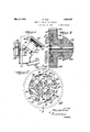
- Fig. 1 represents a diagrammatic side elevation of a machine incorporating the principles of the invention
- Fig. 2 represents a plan of the form of invention used to make open loops on the wire coil showing in dotted lines the initial un looped turn of wire, and in full lines the same after the loops are formed,
- Fig. 3 represents, a fragmentary section taken on line 3- -3 of Fig. 2,
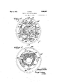
- Fig. 4 represents a plan of the form of invention used to make substantially closed loops on the wirecoil with the wire end shown in dotted lines,
- Fig. 5 represents a plan of the rotating part of the device illustrated in Fig. 4, i
- Fig. 6 represents a fragmentary section taken on line 6-6 of Fig. 4,
- Fig. 7 represents a fragmentary section taken on line 7 -7 of Fig. 4,
- Fig. 8 represents a plan of the stationary guide element or spider of the form of invention used for making the substantially closed loops
- Fig. 9 represents a plan of the ejecting device of the same
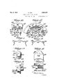
- Fig. 10 represents a fragmentary plan of the invention of Fig. 2, in'loop forming operation
- Fig. 11 represents a fragmentary elevation of a wire with a plurality of loops as formed by the device of Figs. 2 and 10, r
- Fig. 12 represents a fragmentary plan of the invention of Fig. 4 in loop forming op-- eration, I i
- Fig. 13 represents a fragmentary elevation of a wire with a plurality of loops as formed by the device of Figs. 4 and 12,
- Figs. 14 and 15 represent respectively end and side elevations of the movable anvil or die of Figs. 4 and 12, and
- Figs. 16 and 17 represent respectively a plan and an end elevation of the shaping die of Figs. 4 and 12.
- the end turns of the Wire coil forming the spring may be the terminals for any kind or shape of spring, but that as provided for the machine the diameter ofthe end turn will be greater than the finished diameter of the turn with loops, as a certain portion of the periphery of the spring is utilized in forming "the loops. It might be mentioned that the designation loop contemplates bends, hooks, lugs, ears, or any integral projection from the peripheral extent of the wire.
- a frame having an angular support 21 and an angular face plate 22, which latter are in parallel spaced relation.
- A' driven shaft 23 connects with fly-Wheel24, engageable by clutch 25 in any suitable manner to cause shaft 26 to make one revolution and then automatically to be disengaged.
- Such knock-out clutches are quite common in various arts, and are operated in any desired manner, as by depressing treadle 27.
- the face plate 22 is preferably arranged so that there is only exposed a depression large enough to receive the end of the spring when inserted by the operator, and so that the reciprocating and rotating parts are concealed out of possible contact by the hand of the operator.
- the large gear wheel or cam actuator 32 is preferably disposed below the '1 face plate and has suitable guards or housings, and the peripheral teeth 33 thereof are in mesh with pinion gear 30, and the pro portion is such that one revolution of the pinion gear drives the large gear through one quarter of a revolution only, in the event that there are to be four simultaneous looping operations. 'Different numbers of operations will require obvious changes in degree of rotation.
- the large gear is suitably journalled for rotation and has an axial recess 34, and an axial bore 35 communicating V therewith.
- a plurality of roller abutments 36 Mounted on the gear 32, and extending well into the recess 34, are a plurality of roller abutments 36, preferably one for each loop it is desired to form on the end turn of wi e, and which, obviously, follow a circular path in the rotation of the gear 32.
- Mounted in the recess 34 of the gear 32 is the stationary guide element or spider 37 having a shank 38 disposed in the bore 35 of the gear and keyed'to the angular support 21 to prevent rotation of the guide or spider.
- the shank hasan axial bore 40 in which is disposed the 5 longitudinally movable rod 41 of the ejector device to be described, if it is desired to provide an ejector.
- the ejector is not really essential, but may be described in case its use is found helpful.
- it is comprised of a cruciform element 42,.the arms 43 of which extend radially on each side of stationary anvils or bosses 44, the die face of each of which is formed of a substantially rectangular boss fixed to the stationary guide, but replaceable either in the event of wear or in order to change the size of loop.
- Each boss is preferably equally spaced from the stationary crimp guides 47, adjacent guide surfaces of which are in parallelism so as to'guide the inwardly movable crimp elements or dies 48.
- the crimp elements or dies 48 are arranged to have an inwardly disposed cooperating die recess 50, the profile of which is complementary of that of the bosses 44.
- the recesses 50 are rectangular.
- the movable die members or crimps 48 have outwardly disposed cam surfaces 51 arranged to be abutted by the rollers 36 and to be forced inwardly to wire bending engagement with the anvils 44 against the resilience of compression springs 52.
- the ejector device may be actuated in any desired -manner as by a treadle 53, or automatically upon the completion of the quarter revolution of the gear 32.
- the die members are quickly and easily removable and replaceable, so that in the event of wear, or of the use of heavier or. lighter wire than normal, or if it is desired to change the size or proportions of the loops, proper dies can be inserted.
- the end turn of wire 46 will be of a diameter suiiicient to enable the operator to place the wire axially into the die with the turn of wire 46 outside of all of the bosses 44, and resting upon the arms 43 of the ejector if such is used.
- the gear 32 Upon actuation of the clutch device the gear 32 will be driven through one quarter of a revolution, to move the gear with its rollers spaced between came, through a cam abuting engagement, to a secondary position with the rollers disposed between cams.
- each of the die members has been forced radially inward, and a plurality of substantially identical loops 39 have been formed.
- the end turn of wire now of smaller diameter, might be constricted upon the an vils, in which case the ejector moves axially to push the spring from the stationary element.
- a gear or cam actuator 32 having recess and rollers 36 as in the first form described.
- the bottom of recess 34 is formed with a cam groove 59 to actuate the movable anvils to be described.
- the stationary guide element, or spider in this form is quite different, as can be observed in Fig. 8.
- this element 53 has a cruciform recess 54, to receive the ejector 55, (Fig.
- the spider 9 has a plurality of stationary truncated wedge shaped guides 56, the apex of each of which is cut away to form the radial undercut slot 57 extending through the guide element, or spider, and having parallel straight sides and arcuate ends to receive and guide the radially movable anvil to be described.
- the spider las also interrupted segmental arcuate shoulders 49, arranged to form, with the complementary interrupted arcuate shoulders 69 of the spider 55, an annular shoulder against which the end turn of wire may be forced to maintain its annular shape.
- the anvil of this form of invention comprises the oval body 58, having the flange 60 arranged to seat in the undercut portion of the slot, and the depending stud 61 arranged with the sleeve roller 62 to ride in the cam groove 59 in the gear.
- the upper portion of the body 58 is cut back and away to form a pair of converging vertical faces respectively parallel with the faces of the guides 56 forming a substantial point or edge 63, of a triangular anvil lug 64, formed by the transverse slot 65 intersecting the converging faces of the body.
- the edges of the anvil lug are preferably rounded to preclude cutting the wire when the bending takes place.
- cam groove 59 may be so shaped as to hold the anvils inward at the conclusion of the quarter revolution, to facilitate ejection, then to return or retract the anvils by another quarter revolution without the formation of a loop.
- the die members 68 comprise each a flatplate 67 having parallel plane edges for sliding engagement with the respective guide faces of a pair of wedge shaped guides 56, and the inner edge of which is arcuate as at 67.
- Each die member includes the cam surface 68 arranged to be abutted by the respective rollers. The cam surface may be extended vertically to form a shoulder 70 having the recess 71 in which a spring 52 may seat to urge the die members outwardly.
- the anvils remain stationary so that a pair of dies, havconverging paths engage the turn of extending laterally out of the slot of etween the pair of dies and begin c wire inwardly about the corners or the anvil lug 6-4. It will be observed that Continued movement of the die members, and th maintenance of the stationary posi- .ie anvil would cause such flow of i. Under some conditions this might be undesirable and the stationary anvil is contemplated to be used when desired. Hewever, in the preferred. form of the in v-ention, the movable dies approach each of er in their convergent paths, the. cam groove acting on the stud of the anvil causes the anvil to slide inwardly radially of the spring: axis, or in the plane of the end turn,
- each die works in two oops simultaneously, although on one side of each loop.
- the ejector Upon the conclusion of the loop forming operation the ejector is actuated to force the completed spring axially out of the apparatus, and each loop from its frictional engagement with the anvil lugs.
- the large gear 32 may be made a stationary device, with a central rotating cam element forcing dies or anvils radially outward to achieve the same result.
- the device has been illustrated as forming loops in the plane of the end turn it requires but to vhave the dies inclined out of that plane to secure loops which are inclined out of the end turn of the springs and such use is contemplated.
- a pair of guides having converging paths, means for supporting wire in the converging paths, means movable relative to the guides for engaging the wire in each path simultaneousl to bend it relative to the supporting means, a rotatably mounted head concentric with the intersection of the converging paths, means carried by the head for simultaneously actuating the movable means, and means for rotating said head.
- a pair of guides having converging paths intersecting at a common center, means for supporting wire in the converging paths, means movable relative to the guides for engaging the wire in each path simultaneously to bend it relative to the supporting means, said means for support being movable in synchronized relation to the movable means, a rotatable head eonccntric with the intersection of said paths, mea s carried by said head for simultaneously moving all of the engaging elements toward the common center and said head having means for subsequently moving the supporting means during the movement of the engaging means, and means for rotating said head,
- Loop forming apparatus an anvil having a main body and a substantially triangular lug one surface of which is formed by a slot in the main body, said slot arranged to receive a wire, a pair of converging crimpin g elements the paths of which are parallel to respective faces of the lug and operative to bend the wire disposed in the slot, and means operative to move the anvil in a path substantially bisecting the paths of the con verging crimping elements to reduce stretching of the wire outside of the slot.
- Loop forming apparatus comprising a rotatable device having a recess, a non-rotatable spider disposed in the recess guide elements fixed to the spider, crimping devices having cam surfaces and movable relative to the guide elements, abutments carried by the rotatable elements and arranged to engage the cam surfaces to force the guide elements slidably relative to the guide elements, and means operatively associated with the spider relative to which loops are formed.
- Loop forming apparatus comprising a head rotatable about an axis, a spider mounted concentrically with said axis parallel to said head, radial guide elements mounted operatively on the spider, crimping devices having cam surfaces normally extending radially beyond the guide elements and slidable relative to the guide elements, means operatively associated with the spider relative to which loops are formed, and abutments carried by the rotatable device radially outward of the guide elements in position to engage the respective cam surfaces to slide them radially relative to the loop forming means, and means for imparting a limited rotation to said head.
- Loop forming apparatus comprising a head rotatable about an axis, a spider mounted concentrically with said axis parallel to said head, radial guide elements mounted operatively on the spider, crimping devices having cam surfaces normally extending radially beyond the guide elements and slidable relative to the guide elements, means operatively associated with the spider relative to which loops are formed, and abutments carried by the rotatable device radially outward of the guide elements in position to engage the respective cam surfaces to slide them radially relative to the loop forming means, means for imparting a limited rotation to said head, and stripping means movable axially of said head and said spider and relative to the spider associated loop forming means.
- Loop forming apparatus comprising a shank having an axis and a spider extending perpendicularly thereto, guide elements fixed to the spider and forming guideways substantially radially of said axis, anvils operatively associated with said spider and form ing with the spider supports for the end turn of a coil spring to dispose same substantially concentric to said axis, die means slidable in said guideways and relative to said anvils, a rotatable head journalled for rotation about the axis of said shank, means carried by said head in radial alignment with said guides, said abutments arcuately spaced on said head, means for rotating said head, the abutment so disposed as respectively and simultaneously to engage and radially move all of said guides.
Landscapes
- Engineering & Computer Science (AREA)
- Mechanical Engineering (AREA)
- Wire Processing (AREA)
Description
May 9, 1933. w. KIWI FORMING LOOPS ON COIL SPRINGS Filed Aug. 14, 1931 4 Sheets-Sheet l o "*5'3' W 32 @3 I f 54 V 2 .52 Z55 Y INVENT DR. 7, H47 '5 BY MA WW ATTORNEY.
May 9, 1933'. w. KIWI 1,908,367
FORMING LOOPS ON COIL SPRING S Filed Agg. 14, 1931 4 Sheets-Sheet 2 Y INVENTQR. 0 ,QWZE/F/f/W/ BY ATTORNEY.
May 9, 1933. w. KIWI 1,908,367
FORMING LOOPS ON COIL SPRINGS Filed Aug. 14, 1931 4 Shegis-Sheet s J j Q 42 ATTORNEY.
May 9, 1933. w w 1,908,367
FORMING LOOPS ON COIL SPRINGS Filed Aug. 14, 1931 4 Sheets-Sheet 4 97/ lNVliINTOIf. I922 75/? bmq ATTORNEY.
Patented May 9, 1933 UNITED STATES PATENT? OFFICE WALTER- KIWI, OF ANDALUSIA, PENNSYLVANIA, ASSIGNOR TO KIWI MFG. (30., INC
or PHILADELPHIA, PENNSYLVANIA,
A CORPORATION or DELAWARE FORMING LOOPS N COIL SPRINGS Application filed August 14, 1931. Serial No. 556,961.
This invenion relates to the art of forming loops on coil springs.
In coil springs as used in mat assemblies for inner springs of mattresses, seats and the like, it has been usual in the past in the practical commercial exploitationthereof to attach arcuate sections of one coil spring to similar the fact that such loop formation as has been attempted in the past has resulted in' drawing the wire to such thinness as to render the loops weak either in the loop or in the adjacent turn of wire.
It is among the objects of this invention; to provide a machine for forming a loop in an arcuate turn of wire without appreciable weakening of any part of the wire; to provide a loop forming device for coil springs in which a plurality of loops may be formed simultaneously; to provide means for forming substantially closed loops in an arcuate section of a wire; to provide mechanism for forming substantially closed loops in an arcuate wire coil without appreciable drawing of the wire; to provide an anvil and die members operably associated therewith, with means for moving the anvil in the same direction and in synchronism with the die members to prevent wire drawing in bending loops in coil springs; to provide a loop forming device of simplicity and efiiciency arranged to form a plurality of loops in a spring simultaneously in a single cycle of operation of the device; to provide a simple, cheap, and
small sized apparatus for forming simultaneously a multiplicity of loops in the end turn of a wire spring; and many other objects and advantages as will become more apparent as the description proceeds.
In the accompanying drawings, forming part of'this specification;
Fig. 1 represents a diagrammatic side elevation of a machine incorporating the principles of the invention Fig. 2 represents a plan of the form of invention used to make open loops on the wire coil showing in dotted lines the initial un looped turn of wire, and in full lines the same after the loops are formed,
Fig. 3 represents, a fragmentary section taken on line 3- -3 of Fig. 2,
, Fig. 4 represents a plan of the form of invention used to make substantially closed loops on the wirecoil with the wire end shown in dotted lines,
Fig. 5 represents a plan of the rotating part of the device illustrated in Fig. 4, i
Fig. 6 represents a fragmentary section taken on line 6-6 of Fig. 4,
Fig. 7 represents a fragmentary section taken on line 7 -7 of Fig. 4,
Fig. 8 represents a plan of the stationary guide element or spider of the form of invention used for making the substantially closed loops,
Fig. 9 represents a plan of the ejecting device of the same,
Fig. 10 represents a fragmentary plan of the invention of Fig. 2, in'loop forming operation,
Fig. 11 represents a fragmentary elevation of a wire with a plurality of loops as formed by the device of Figs. 2 and 10, r
Fig. 12 represents a fragmentary plan of the invention of Fig. 4 in loop forming op-- eration, I i
Fig. 13 represents a fragmentary elevation of a wire with a plurality of loops as formed by the device of Figs. 4 and 12,
Figs. 14 and 15 represent respectively end and side elevations of the movable anvil or die of Figs. 4 and 12, and
Figs. 16 and 17 represent respectively a plan and an end elevation of the shaping die of Figs. 4 and 12.
It will be understood that the preferred use of the invention herein set forth is in forming loopsor hooks on the end or other turns of coil springs to form anchorages for attaching clips or the like. It will, however, be understood that the machine and apparatus herein set forth may be used in whole or in part to form bends of various sorts in wire of any kind.
It will be understood that the end turns of the Wire coil forming the spring may be the terminals for any kind or shape of spring, but that as provided for the machine the diameter ofthe end turn will be greater than the finished diameter of the turn with loops, as a certain portion of the periphery of the spring is utilized in forming "the loops. It might be mentioned that the designation loop contemplates bends, hooks, lugs, ears, or any integral projection from the peripheral extent of the wire.
Referring now to Fig. 1, there is disclosed a frame having an angular support 21 and an angular face plate 22, which latter are in parallel spaced relation. A' driven shaft 23 connects with fly-Wheel24, engageable by clutch 25 in any suitable manner to cause shaft 26 to make one revolution and then automatically to be disengaged. Such knock-out clutches are quite common in various arts, and are operated in any desired manner, as by depressing treadle 27. Shaft 26, driving through gears or through a universal joint 28, drives the pinion gear 30 through one revolution, by means of the shaft 31." The face plate 22 is preferably arranged so that there is only exposed a depression large enough to receive the end of the spring when inserted by the operator, and so that the reciprocating and rotating parts are concealed out of possible contact by the hand of the operator. The large gear wheel or cam actuator 32 is preferably disposed below the '1 face plate and has suitable guards or housings, and the peripheral teeth 33 thereof are in mesh with pinion gear 30, and the pro portion is such that one revolution of the pinion gear drives the large gear through one quarter of a revolution only, in the event that there are to be four simultaneous looping operations. 'Different numbers of operations will require obvious changes in degree of rotation. The large gear is suitably journalled for rotation and has an axial recess 34, and an axial bore 35 communicating V therewith.
Mounted on the gear 32, and extending well into the recess 34, are a plurality of roller abutments 36, preferably one for each loop it is desired to form on the end turn of wi e, and which, obviously, follow a circular path in the rotation of the gear 32. Mounted in the recess 34 of the gear 32 is the stationary guide element or spider 37 having a shank 38 disposed in the bore 35 of the gear and keyed'to the angular support 21 to prevent rotation of the guide or spider. The shank hasan axial bore 40 in which is disposed the 5 longitudinally movable rod 41 of the ejector device to be described, if it is desired to provide an ejector. With the instant form of the invention the ejector is not really essential, but may be described in case its use is found helpful. As disclosed it is comprised of a cruciform element 42,.the arms 43 of which extend radially on each side of stationary anvils or bosses 44, the die face of each of which is formed of a substantially rectangular boss fixed to the stationary guide, but replaceable either in the event of wear or in order to change the size of loop. Each boss is preferably equally spaced from the stationary crimp guides 47, adjacent guide surfaces of which are in parallelism so as to'guide the inwardly movable crimp elements or dies 48. The crimp elements or dies 48 are arranged to have an inwardly disposed cooperating die recess 50, the profile of which is complementary of that of the bosses 44. In the instant disclosure the recesses 50 are rectangular. It will be understood that the movable die members or crimps 48 have outwardly disposed cam surfaces 51 arranged to be abutted by the rollers 36 and to be forced inwardly to wire bending engagement with the anvils 44 against the resilience of compression springs 52. It will be understood that the ejector device may be actuated in any desired -manner as by a treadle 53, or automatically upon the completion of the quarter revolution of the gear 32. The die members are quickly and easily removable and replaceable, so that in the event of wear, or of the use of heavier or. lighter wire than normal, or if it is desired to change the size or proportions of the loops, proper dies can be inserted.
In the operation of the device so far described it will be understood that the end turn of wire 46 will be of a diameter suiiicient to enable the operator to place the wire axially into the die with the turn of wire 46 outside of all of the bosses 44, and resting upon the arms 43 of the ejector if such is used. Upon actuation of the clutch device the gear 32 will be driven through one quarter of a revolution, to move the gear with its rollers spaced between came, through a cam abuting engagement, to a secondary position with the rollers disposed between cams. Meanwhile each of the die members has been forced radially inward, and a plurality of substantially identical loops 39 have been formed. At the conclusion of the'bending operation it might be that the end turn of wire, now of smaller diameter, might be constricted upon the an vils, in which case the ejector moves axially to push the spring from the stationary element.
As noted, in forming the loops of the type which might be described as open, as shown in Fig. 11, with care in the selection of a good quality of wire, the wire will not be drawn to a harmful extent and the loops as formed will be quite satisfactory for all purposes. However, the formation of loops of the substanti'a lly closed type, as illustrated in Fig. 13, has always hitherto been impossible (so far as known) except as a painstaking manual operation, which obviously has no part in the commercial utilization of springs of this type at this time.
Referring now to Figs. 4 and 5, there is provided a gear or cam actuator 32, having recess and rollers 36 as in the first form described. In this case however the bottom of recess 34 is formed with a cam groove 59 to actuate the movable anvils to be described. The stationary guide element, or spider in this form, is quite different, as can be observed in Fig. 8. Thus this element 53, has a cruciform recess 54, to receive the ejector 55, (Fig. 9), has a plurality of stationary truncated wedge shaped guides 56, the apex of each of which is cut away to form the radial undercut slot 57 extending through the guide element, or spider, and having parallel straight sides and arcuate ends to receive and guide the radially movable anvil to be described. The spider las also interrupted segmental arcuate shoulders 49, arranged to form, with the complementary interrupted arcuate shoulders 69 of the spider 55, an annular shoulder against which the end turn of wire may be forced to maintain its annular shape.
Referring to Figs. 14 and 15. the anvil of this form of invention comprises the oval body 58, having the flange 60 arranged to seat in the undercut portion of the slot, and the depending stud 61 arranged with the sleeve roller 62 to ride in the cam groove 59 in the gear. The upper portion of the body 58 is cut back and away to form a pair of converging vertical faces respectively parallel with the faces of the guides 56 forming a substantial point or edge 63, of a triangular anvil lug 64, formed by the transverse slot 65 intersecting the converging faces of the body. The edges of the anvil lug are preferably rounded to preclude cutting the wire when the bending takes place. It will be under stood that with the movable anvils in the guiding slots in the stationary guide element, and with the respective studs 61 in the cam groove 59, that with the quarter revolution the anvils will each have been moved radially inwardly through the cam action of the groove 59 on the studs or pins 61, and preferably back again to their retracted position. Obviously the cam groove 59 may be so shaped as to hold the anvils inward at the conclusion of the quarter revolution, to facilitate ejection, then to return or retract the anvils by another quarter revolution without the formation of a loop.
As disclosed in Figs. 16 and 17 the die members 68 comprise each a flatplate 67 having parallel plane edges for sliding engagement with the respective guide faces of a pair of wedge shaped guides 56, and the inner edge of which is arcuate as at 67. Each die member includes the cam surface 68 arranged to be abutted by the respective rollers. The cam surface may be extended vertically to form a shoulder 70 having the recess 71 in which a spring 52 may seat to urge the die members outwardly.
It will be understood that in the position of rest disclosed in Fig. l, there is clearance provided in the device whereby the arcuate end turn of wire of a coil spring may be dropped to a supported position in the apparatus, with th arcuate wire disposed in the respective slots -65 of the retracted anvils. Upon the cyclic rotation of the gear 32 through its quarter of a revolution, (as shown in Fig. 12) rollers 36 engage simultaneously all of the cam surfaces of the die members and press them radially inward.
During the first portion of the inward movement of the die members, the anvils remain stationary so that a pair of dies, havconverging paths engage the turn of extending laterally out of the slot of etween the pair of dies and begin c wire inwardly about the corners or the anvil lug 6-4. It will be observed that Continued movement of the die members, and th maintenance of the stationary posi- .ie anvil would cause such flow of i. Under some conditions this might be undesirable and the stationary anvil is contemplated to be used when desired. Hewever, in the preferred. form of the in v-ention, the movable dies approach each of er in their convergent paths, the. cam groove acting on the stud of the anvil causes the anvil to slide inwardly radially of the spring: axis, or in the plane of the end turn,
during the next step of the loop formawe dies are moving in converging rela- .n and the anvil s moving in a path big the angular paths of the dies, so that the conclusion of the bending operation is re. bv the forcing of the legs of the loop five to the base of the loop contained in the s ot Although the wire is forced against the annular shoulders of the spider and f orjit has such resilience as to spring outward rom such shoulders upon retraction of the dies. and thus to provide stretch enough to permit the anvilsto be retracted. I
It will be observed that in this last deed f rm of the invention each die works in two oops simultaneously, although on one side of each loop.
Upon the conclusion of the loop forming operation the ejector is actuated to force the completed spring axially out of the apparatus, and each loop from its frictional engagement with the anvil lugs.
aterial as to render it very thin and.
3; inwardly without stretching the legs rela-.
' It will be clear that under the broad scope of the invention, the large gear 32 may be made a stationary device, with a central rotating cam element forcing dies or anvils radially outward to achieve the same result. ldoreover, although the device has been illustrated as forming loops in the plane of the end turn it requires but to vhave the dies inclined out of that plane to secure loops which are inclined out of the end turn of the springs and such use is contemplated.
I claim:
1. In combination, a pair of guides having converging paths, means for supporting wire in the converging paths, means movable relative to the guides for engaging the wire in each path simultaneousl to bend it relative to the supporting means, a rotatably mounted head concentric with the intersection of the converging paths, means carried by the head for simultaneously actuating the movable means, and means for rotating said head.
2. In combination a pair of guides having converging paths intersecting at a common center, means for supporting wire in the converging paths, means movable relative to the guides for engaging the wire in each path simultaneously to bend it relative to the supporting means, said means for support being movable in synchronized relation to the movable means, a rotatable head eonccntric with the intersection of said paths, mea s carried by said head for simultaneously moving all of the engaging elements toward the common center and said head having means for subsequently moving the supporting means during the movement of the engaging means, and means for rotating said head,
3. Loop forming apparatus, an anvil having a main body and a substantially triangular lug one surface of which is formed by a slot in the main body, said slot arranged to receive a wire, a pair of converging crimpin g elements the paths of which are parallel to respective faces of the lug and operative to bend the wire disposed in the slot, and means operative to move the anvil in a path substantially bisecting the paths of the con verging crimping elements to reduce stretching of the wire outside of the slot.
4. Loop forming apparatus comprising a rotatable device having a recess, a non-rotatable spider disposed in the recess guide elements fixed to the spider, crimping devices having cam surfaces and movable relative to the guide elements, abutments carried by the rotatable elements and arranged to engage the cam surfaces to force the guide elements slidably relative to the guide elements, and means operatively associated with the spider relative to which loops are formed.
5. Loop forming apparatus comprising a head rotatable about an axis, a spider mounted concentrically with said axis parallel to said head, radial guide elements mounted operatively on the spider, crimping devices having cam surfaces normally extending radially beyond the guide elements and slidable relative to the guide elements, means operatively associated with the spider relative to which loops are formed, and abutments carried by the rotatable device radially outward of the guide elements in position to engage the respective cam surfaces to slide them radially relative to the loop forming means, and means for imparting a limited rotation to said head.
6. Loop forming apparatus comprising a head rotatable about an axis, a spider mounted concentrically with said axis parallel to said head, radial guide elements mounted operatively on the spider, crimping devices having cam surfaces normally extending radially beyond the guide elements and slidable relative to the guide elements, means operatively associated with the spider relative to which loops are formed, and abutments carried by the rotatable device radially outward of the guide elements in position to engage the respective cam surfaces to slide them radially relative to the loop forming means, means for imparting a limited rotation to said head, and stripping means movable axially of said head and said spider and relative to the spider associated loop forming means.
7. Loop forming apparatus comprising a shank having an axis and a spider extending perpendicularly thereto, guide elements fixed to the spider and forming guideways substantially radially of said axis, anvils operatively associated with said spider and form ing with the spider supports for the end turn of a coil spring to dispose same substantially concentric to said axis, die means slidable in said guideways and relative to said anvils, a rotatable head journalled for rotation about the axis of said shank, means carried by said head in radial alignment with said guides, said abutments arcuately spaced on said head, means for rotating said head, the abutment so disposed as respectively and simultaneously to engage and radially move all of said guides.
Sign-ed at Philadelphia, county of Philadelphia and State of Pennsylvania, this 12th day of August, 1931. 1
WALTER KIlVI.
Priority Applications (1)
| Application Number | Priority Date | Filing Date | Title |
|---|---|---|---|
| US556961A US1908367A (en) | 1931-08-14 | 1931-08-14 | Forming loops on coil springs |
Applications Claiming Priority (1)
| Application Number | Priority Date | Filing Date | Title |
|---|---|---|---|
| US556961A US1908367A (en) | 1931-08-14 | 1931-08-14 | Forming loops on coil springs |
Publications (1)
| Publication Number | Publication Date |
|---|---|
| US1908367A true US1908367A (en) | 1933-05-09 |
Family
ID=24223512
Family Applications (1)
| Application Number | Title | Priority Date | Filing Date |
|---|---|---|---|
| US556961A Expired - Lifetime US1908367A (en) | 1931-08-14 | 1931-08-14 | Forming loops on coil springs |
Country Status (1)
| Country | Link |
|---|---|
| US (1) | US1908367A (en) |
Cited By (6)
| Publication number | Priority date | Publication date | Assignee | Title |
|---|---|---|---|---|
| US2873768A (en) * | 1953-11-09 | 1959-02-17 | Us Bedding Co | Wire shaping machine |
| US3048199A (en) * | 1956-03-29 | 1962-08-07 | A H Nilson Machine Company | Vertical four slide wire or ribbon metal forming machine |
| US3049154A (en) * | 1958-04-18 | 1962-08-14 | Eclipse Sleep Products Inc | Machine and method for forming wire units |
| US3049155A (en) * | 1959-03-25 | 1962-08-14 | Eclipse Sleep Products Inc | Machine and method for forming wire units |
| US3094764A (en) * | 1957-04-03 | 1963-06-25 | Rauland Corp | Apparatus for manufacturing semiconductor devices |
| US3209791A (en) * | 1960-03-10 | 1965-10-05 | Ira J Boots | Rotary press |
-
1931
- 1931-08-14 US US556961A patent/US1908367A/en not_active Expired - Lifetime
Cited By (6)
| Publication number | Priority date | Publication date | Assignee | Title |
|---|---|---|---|---|
| US2873768A (en) * | 1953-11-09 | 1959-02-17 | Us Bedding Co | Wire shaping machine |
| US3048199A (en) * | 1956-03-29 | 1962-08-07 | A H Nilson Machine Company | Vertical four slide wire or ribbon metal forming machine |
| US3094764A (en) * | 1957-04-03 | 1963-06-25 | Rauland Corp | Apparatus for manufacturing semiconductor devices |
| US3049154A (en) * | 1958-04-18 | 1962-08-14 | Eclipse Sleep Products Inc | Machine and method for forming wire units |
| US3049155A (en) * | 1959-03-25 | 1962-08-14 | Eclipse Sleep Products Inc | Machine and method for forming wire units |
| US3209791A (en) * | 1960-03-10 | 1965-10-05 | Ira J Boots | Rotary press |
Similar Documents
| Publication | Publication Date | Title |
|---|---|---|
| US1972789A (en) | Machine for and method of making commutator rings | |
| US1908367A (en) | Forming loops on coil springs | |
| US1433879A (en) | Coiling machine | |
| US1904920A (en) | Apparatus for forming sheet metal caps | |
| US2978932A (en) | Forming press | |
| US1474882A (en) | Die | |
| US2374301A (en) | Trimming apparatus | |
| US1920303A (en) | Method of and machine for making wheel rims | |
| US2211009A (en) | Metalworking machine | |
| US2299606A (en) | Method of making slide fasteners | |
| US2302075A (en) | Slide fastener manufacture | |
| US2266997A (en) | Dieing machine | |
| US2074678A (en) | Means and method for making nuts | |
| US1818332A (en) | Thimble making machine | |
| US2228494A (en) | Hoop forming apparatus | |
| US2447499A (en) | Brush-stem forming machine | |
| US1705821A (en) | Machine for fabricating wire-spring structures | |
| US2462080A (en) | Apparatus for shaping containers | |
| US1512990A (en) | Method and means for fabricating spring structures | |
| US2559904A (en) | Apparatus for crimping condenser cans having leads | |
| US2290263A (en) | Slide fastener element and method of making slide fasteners | |
| US887630A (en) | Machine for making washers. | |
| US1756434A (en) | Machine for fabricating spring structures | |
| US409643A (en) | manyille | |
| USRE19927E (en) | Method and machine fob forming |