US1908363A - Method of making heat exchangers - Google Patents
Method of making heat exchangers Download PDFInfo
- Publication number
- US1908363A US1908363A US482669A US48266930A US1908363A US 1908363 A US1908363 A US 1908363A US 482669 A US482669 A US 482669A US 48266930 A US48266930 A US 48266930A US 1908363 A US1908363 A US 1908363A
- Authority
- US
- United States
- Prior art keywords
- tubes
- tube
- return bend
- tubular
- enveloping
- Prior art date
- Legal status (The legal status is an assumption and is not a legal conclusion. Google has not performed a legal analysis and makes no representation as to the accuracy of the status listed.)
- Expired - Lifetime
Links
- 238000004519 manufacturing process Methods 0.000 title description 5
- QSHDDOUJBYECFT-UHFFFAOYSA-N mercury Chemical compound [Hg] QSHDDOUJBYECFT-UHFFFAOYSA-N 0.000 description 13
- 229910052753 mercury Inorganic materials 0.000 description 8
- 239000003921 oil Substances 0.000 description 6
- 239000012530 fluid Substances 0.000 description 5
- 238000000034 method Methods 0.000 description 4
- 238000003466 welding Methods 0.000 description 4
- 238000010276 construction Methods 0.000 description 3
- 230000008602 contraction Effects 0.000 description 2
- 239000013529 heat transfer fluid Substances 0.000 description 2
- 229910052751 metal Inorganic materials 0.000 description 2
- 239000002184 metal Substances 0.000 description 2
- 239000004215 Carbon black (E152) Substances 0.000 description 1
- 229910000831 Steel Inorganic materials 0.000 description 1
- 230000015572 biosynthetic process Effects 0.000 description 1
- 238000005266 casting Methods 0.000 description 1
- 238000004140 cleaning Methods 0.000 description 1
- 229930195733 hydrocarbon Natural products 0.000 description 1
- 150000002430 hydrocarbons Chemical class 0.000 description 1
- 239000007788 liquid Substances 0.000 description 1
- 230000000284 resting effect Effects 0.000 description 1
- 239000010959 steel Substances 0.000 description 1
Images

Classifications
-
- F—MECHANICAL ENGINEERING; LIGHTING; HEATING; WEAPONS; BLASTING
- F28—HEAT EXCHANGE IN GENERAL
- F28D—HEAT-EXCHANGE APPARATUS, NOT PROVIDED FOR IN ANOTHER SUBCLASS, IN WHICH THE HEAT-EXCHANGE MEDIA DO NOT COME INTO DIRECT CONTACT
- F28D7/00—Heat-exchange apparatus having stationary tubular conduit assemblies for both heat-exchange media, the media being in contact with different sides of a conduit wall
- F28D7/10—Heat-exchange apparatus having stationary tubular conduit assemblies for both heat-exchange media, the media being in contact with different sides of a conduit wall the conduits being arranged one within the other, e.g. concentrically
- F28D7/14—Heat-exchange apparatus having stationary tubular conduit assemblies for both heat-exchange media, the media being in contact with different sides of a conduit wall the conduits being arranged one within the other, e.g. concentrically both tubes being bent
-
- Y—GENERAL TAGGING OF NEW TECHNOLOGICAL DEVELOPMENTS; GENERAL TAGGING OF CROSS-SECTIONAL TECHNOLOGIES SPANNING OVER SEVERAL SECTIONS OF THE IPC; TECHNICAL SUBJECTS COVERED BY FORMER USPC CROSS-REFERENCE ART COLLECTIONS [XRACs] AND DIGESTS
- Y10—TECHNICAL SUBJECTS COVERED BY FORMER USPC
- Y10T—TECHNICAL SUBJECTS COVERED BY FORMER US CLASSIFICATION
- Y10T29/00—Metal working
- Y10T29/49—Method of mechanical manufacture
- Y10T29/4935—Heat exchanger or boiler making
- Y10T29/49361—Tube inside tube
Definitions
- This invention therefore relates to a mercury or other vapor heat exchanger including tubular members, each of which is so assembled that an uncommon degree of stress elongation may take place without producing leakage of the component elements, and in which highly eflicient heat transfer is accomplished by an arrangement of tubes, one within another, which permits the formation of an enveloping film of mercury vapor in a jacket around the body of heat receiving oil and co-extensive therewith, and separated therefrom by a thin metal wall acting as a heat transfer medium.
- each tubular loop member includes an outer tube jacket and an inner tube annularly spaced throughout their length, and the tubeshave different radii at their bends whereby increased clearance is provided at the loop permitting longitudinal expansion of the one with respect to the other, the return bend of each loop also having a radius sufficient to permit removal of deposits therein by the usual turbining methods now in practice, all joints between tubes being welded to prevent leakage of mercury or other vapor.
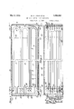
- FIG. 1 is a top plan view of an exchanger with the enclosing casing cut away in a transverse plane to show the arrangement of tubular members;
- Fig. 2 is a side elevation with the enclosing casing cutjthrough in a vertical plane to expose the tubular loop elements;
- Fig. 3 is an end .elevation with the casing cut through in a vertical plane to show the arrangement of tubular loop members
- Fig. 4 is an end elevation similar to that shown in Fig. 3 but of the opposite end, thereby showing the arrangement of the return bend fittings whereby the inner tubes are connected in series;
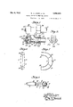
- Fig. 5 is a side elevation partly in section lllustrating the construction of the return bend fittings used to interconnect the inner tubes of the tubular loop members;
- Fig. 6 is an end elevation of assembled halves of the return bend which ultimately forms an integral part of each tubular loop member
- Fig. 7 is a plan view showing the interior of the lower half of the return bend illustrated in Fig. 6;
- Fig. 8 is a sectional view of one return bend ita longL the vertical plane 88 indicated in Fig. 9 is a fragmentary end view of Fig. 5.
- the invention as "illustrated in the drawings, includes a bank of tubular loop members 1 each of identical construction, as will be hereinafter set forth, the banks being divided into groups lettered A, B and C. Each group comprises a number of these horizontal tubular loop members 1 in piled relation, one overlying the other.
- Each tubular loop member includes an inner tube 2 bent at 180 degrees to form a return loop having the legs 3 and 4, and surrounding Which is an enveloping jacket tube 5 of larger diameter than the tube 2 and thus spaced from the outside of tube 2 throughout its length so as to form .the annular passage 6 between the two tubes.
- the ability to take care of expansive elongation of the one with respect to the other becomes of prime importance; with the outer or enveloping jacket tube 5 at a temperature of approximately 900 degrees Fahr., and the inner tube at a much lower temperature, considerable elongation of the outer tube 5, with respect to the inner tube 2, will take place; this is taken care of by making the return bend of the outer or jacket tube with a radius providing sufiicient clearance as shown so that both expansion and contraction are taken care of without imposing any undue stress upon the tubes and welds, or, in other words, the tubular loop member is selfprotecting in regard to expansion and contraction.
- the return bend of the outer jacket tube 5 is made up by combining two pressed steel halves 7 and 8 diametrically increased in cross section intermediate the extremities which, when assembled, fit in closely abutting relation and are joined by welding along the seams 9.
- the extremities of this bend are of the same cross section as the enveloping tubular member 5 as indicated at 10, and when the assembled return bend is placed in position the parallel legs of the enveloping tubular member 5 are in closely abutting relation with the ends 10 of the return bend and are welded thereto as at 11, thereby providing a looped enveloping tube with an enlarged return bend affording clearance.
- the lower half of the return bend has supporting ribs 12 and 13 which carry the return bend of the inner tube 2 and permit a sliding action between the tubes 2 and 5 when elongation takes lace.
- the inner tubular member 2 has its legs 3 and 4 slipped into the enveloping tubes 14 and 15 which, together with the return bend built up as previously described are to form the completed enveloping tube 5.
- the ends of the completedtube are welded as at 16 and 17 to the outer surface of the inner tube legs 3 and 4, respectively, the two tube loops being so placed with respect to each other'that their normal relation, in a cooled condition, is as indicated in Figs.
- the return bend fitting which is used to interconnect the looped tubes 2 has duplicated heads 18 and 19 joined together in an integral casting by metal forming a passage 20 directed at 180 degrees, but with the inlet and outlet thereof extended axially to form continuations of the tube passages as indicated at 21.
- Each passage 21 has a tapered seat 22 at its outer end against which a closure plug 23 is clamped, said plug also having a tapered face cooperating with the seat 22 to form a pressure-tight joint.
- This plug 23 is secured in place by an undercut groove 24 which produces an overhanging lip 25 under which rests the ledge 26 of a two-part clamping member said lip 25 being cut away for a portion of its periphery to permit the placing and removing of the clamping member.
- This two-part clamping member has a circular nut 27 carrying the ledge 26 and is threaded as at 28 to receive a jacking screw 29, the end 30 of which abutts the plug 23 and holds the latter in place.
- the entrance ends 31 and 32 of the return bend fitting are provided, exteriorly, .1 with lugs 33 for limiting the proximity of tubular members.
- These ends 31 and 32 are counterbored as at 34 and are further provided with circumferential grooves 35 so that the ends of the inner tubes 2 of the loop members 100 may be expanded to a fluid-tight fit against the walls of the entrance passages of the re- .turn bend fittings.
- the tubes 2 may be cleaned by the usual turbining methods, the radius of the bend at the opposite end of the tube being suflicient to permit of this.
- FIG. 5 With reference to Figs. 3 and 4, it will be seen that return bend fittings of the type illustrated in Fig. 5, and just described, are used to interconnect the inner tubes 2 in series and to connect the groups A, B and C together.
- An entrance fitting 36 is provided at the lowermost tubular loop member of onei .15 outside group C, and an outlet fitting 37 at the uppermost tubular loop member of the other outside group A so that circulation of oil to be treated will take place from the bottom of one group C to the top thereof, thence from .1 the top of group B to the bottom thereof, and from the bottom of the group A to the top, during which circulation the exchange of heat between the heat transfer medium and the oil will take place.
- the heat transferring medium contemplated for use in this exchanger is mercuryvapor, and to that end there has been provided a distributing system of piping comprised of a feeder pipe 38 with branches 39 and lead- 7 each row of tubular members, and while only ers 40 connected into and distributing mercury vapor to the annular enveloping passages 6 formed by the tubes 2 and 5 of the tubular loop members lying one within the other, while the liquid mercury is collected at the bottoms of the enlarged center portion of the return bends formed by the welded halves 7 and 8 and drained away through connections 41 to the return pipe 42 of the mercury system, the condensed mercury being vaporized and again circulated in vapor form.
- the enclosing casing of the bank of tubular loop heat exchangers may be of any simple form, but in the present instance it has been shown as of box-like construction, the bottom having a cross member 43 upon which rests a channel member 44 in which the downwardly projecting lugs- 33 of the lowermost return bend fittings are seated.
- the walls of the enclosing casing are of fiat plates 45 and 46 forming the ends, each provided with angle members 47 adapted to be placed in abutting relation with'the loops of channel members 48 and 49' which serve to hold the top plates 50 and side plates 51 in position.
- a support for the return bend end of the tubular loop members is a support for the return bend end of the tubular loop members, this support comprising a pair of upright channel members 52 on opposite sides of the heat exchanger and which serves to support their adjacent side plates 51, but through the web is cold whereby clearance is provided for relative expansion of the tubes without strain on the welded terminal unctions of the tubes.
- the method of assembling a heat exchanger unit which comprises forming a return bendtube for the heat recipient fluid, slipping a larger tube over each leg of said bend, welding the terminal ends of the larger tubes to those of the smaller tubes with the tubes held in concentric relation to form a coextensive heat transfer jacket around the inner tube, and welding together two halves of a return bend over the inner tube to enclose the same and to the ends of the outer tube to complete the jacket, the said outer tube return bend having an increasing cross sectional diameter from each extremity toward the center thereof to provide clearance for relative movement of the two tubes when heated.
- any of the usual forms of insulation against heat loss may be provided on the casing, such for instance as asbestos, magnesia or rock wool.
- What I claim is 1.-The method of assembling a heat exchanger unit which comprises forming a return bend tube for the heat recipient fluid, slipping a larger tube over each leg of the said bend whereby a passage is formed around the first named tube for the heat transfer fluid, welding the tubes in concentric relation at the terminal ends, and forming a return bend connection enclosing the bend of the first tube and connecting the remaining extremities of the larger tubes and with the inner tube lying adjacent the extreme wall of the outer tube return'bend when the unit
Landscapes
- Engineering & Computer Science (AREA)
- Physics & Mathematics (AREA)
- Thermal Sciences (AREA)
- Mechanical Engineering (AREA)
- General Engineering & Computer Science (AREA)
- Heat-Exchange Devices With Radiators And Conduit Assemblies (AREA)
Description
May 9 1933. w. A. JONES ET AL METHOD OF MAKING HEAT EXCHANGERS 3 Sheets-Sheet 1 Filed Sept. 18, 1930 m} Q g nes 3% INVENTQRQQ -19 John Pre e THEIR A QRNEY May 9, 1933. w A, JONES ET AL 1,908,363
' METHOD OF MAKING HEAT EXCHANGERS Filed Sept. 18, 1930 3 Sheets-Sheet THElR AT OR EY y 1933- w. A. JONES ET AL 1,908,363
METHOD OF MAKING HEAT EXCHANGERS Filed Sept. 18, 1930 5 SheetS-Sheet I5 I VENTOR W09. Jones 7101/ Preniiae THEIRAT ORN Y Patented May 9, 1933 UNITED STATES PATENT OFFICE WILLIAM A. JONES, OF WEST NEW BRIGHTON, NEW YORK, AND JOHN PRENTIGE, OF BAYONNE, NEW JERSEY, ASSIGNORS TO THE BABCOCK 8a WILGOX COMPANY, OF BAYONNE, NEW JERSEY, A CORPORATION OF NEW JERSEY METHOD OF MAKING HEAT EXCHANGERS Application filed September 18, 1930. Serial No. 482,669.
In treating hydrocarbon oils the use of mercury vapor, or other highly heated vapor, as a heat transfer fluid introduces a dliferential in temperature between the parts carrying the respective fluids, that renders it difficult to build heat exchangers capable of withstanding the stresses set up by the temperature difference without producmg leaks which cause serious direct loss of the mercury, or losses due to intermingling of the mercury and oil.
This invention therefore relates to a mercury or other vapor heat exchanger including tubular members, each of which is so assembled that an uncommon degree of stress elongation may take place without producing leakage of the component elements, and in which highly eflicient heat transfer is accomplished by an arrangement of tubes, one within another, which permits the formation of an enveloping film of mercury vapor in a jacket around the body of heat receiving oil and co-extensive therewith, and separated therefrom by a thin metal wall acting as a heat transfer medium.
To accomplish this result each tubular loop member includes an outer tube jacket and an inner tube annularly spaced throughout their length, and the tubeshave different radii at their bends whereby increased clearance is provided at the loop permitting longitudinal expansion of the one with respect to the other, the return bend of each loop also having a radius sufficient to permit removal of deposits therein by the usual turbining methods now in practice, all joints between tubes being welded to prevent leakage of mercury or other vapor.
To connect the inner tubes of the tubular loop members in series return bend fittings are provided each of which is so formed that, in addition to a passage directing the fluid flow at 180 degrees, there are also passages forming continuations of the inner tubes of connected loops, said continuation passages being closedby removable plugs which permit cleaning of the inner tubes by simply removing caps and working therethrough with the usual turbinin equipment, and thus avoiding the necesslty of making a disconnecting joint between the tubes and fittings with the consequent grief encountered in maintaining such joints free of leakage where high temperatures and pressures prevail.
In the drawings which illustrate a practical form which the invention may assume- Fig. 1 is a top plan view of an exchanger with the enclosing casing cut away in a transverse plane to show the arrangement of tubular members;
Fig. 2 is a side elevation with the enclosing casing cutjthrough in a vertical plane to expose the tubular loop elements;
Fig. 3 is an end .elevation with the casing cut through in a vertical plane to show the arrangement of tubular loop members;
Fig. 4 is an end elevation similar to that shown in Fig. 3 but of the opposite end, thereby showing the arrangement of the return bend fittings whereby the inner tubes are connected in series;
Fig. 5 is a side elevation partly in section lllustrating the construction of the return bend fittings used to interconnect the inner tubes of the tubular loop members;
Fig. 6 is an end elevation of assembled halves of the return bend which ultimately forms an integral part of each tubular loop member;
Fig. 7 is a plan view showing the interior of the lower half of the return bend illustrated in Fig. 6;
Fig. 8 is a sectional view of one return bend ita longL the vertical plane 88 indicated in Fig. 9 is a fragmentary end view of Fig. 5.
The invention, as "illustrated in the drawings, includes a bank of tubular loop members 1 each of identical construction, as will be hereinafter set forth, the banks being divided into groups lettered A, B and C. Each group comprises a number of these horizontal tubular loop members 1 in piled relation, one overlying the other.
Each tubular loop member includes an inner tube 2 bent at 180 degrees to form a return loop having the legs 3 and 4, and surrounding Which is an enveloping jacket tube 5 of larger diameter than the tube 2 and thus spaced from the outside of tube 2 throughout its length so as to form .the annular passage 6 between the two tubes.
Due to the length of the component tubes 2 and of the tubular loop members, and the high temperature and pressure at which the exchanger, of which they are a part, is operated, the ability to take care of expansive elongation of the one with respect to the other, becomes of prime importance; with the outer or enveloping jacket tube 5 at a temperature of approximately 900 degrees Fahr., and the inner tube at a much lower temperature, considerable elongation of the outer tube 5, with respect to the inner tube 2, will take place; this is taken care of by making the return bend of the outer or jacket tube with a radius providing sufiicient clearance as shown so that both expansion and contraction are taken care of without imposing any undue stress upon the tubes and welds, or, in other words, the tubular loop member is selfprotecting in regard to expansion and contraction.
The return bend of the outer jacket tube 5 is made up by combining two pressed steel halves 7 and 8 diametrically increased in cross section intermediate the extremities which, when assembled, fit in closely abutting relation and are joined by welding along the seams 9. The extremities of this bend are of the same cross section as the enveloping tubular member 5 as indicated at 10, and when the assembled return bend is placed in position the parallel legs of the enveloping tubular member 5 are in closely abutting relation with the ends 10 of the return bend and are welded thereto as at 11, thereby providing a looped enveloping tube with an enlarged return bend affording clearance. The lower half of the return bend has supporting ribs 12 and 13 which carry the return bend of the inner tube 2 and permit a sliding action between the tubes 2 and 5 when elongation takes lace. p In assembling the tubular members 2 and 5 the inner tubular member 2 has its legs 3 and 4 slipped into the enveloping tubes 14 and 15 which, together with the return bend built up as previously described are to form the completed enveloping tube 5. The ends of the completedtube are welded as at 16 and 17 to the outer surface of the inner tube legs 3 and 4, respectively, the two tube loops being so placed with respect to each other'that their normal relation, in a cooled condition, is as indicated in Figs. 1, 2 and 8 with the outer side of the return bend of the inner tube 2 lying substantially against the inner wall of the return bend of the enveloping tube 5 and with the-lower side of the inner tube 2 resting upon the ribs 12 and 13; thus, as the enveloping tube 5 lengthens out the enlarged space formed by the welded return bend halves 7 and 8 afl'ords clearance for the elongation of the enveloping tube 5 with respect to the inner tube 2 and, at operating temperatures, positions the inner tube 2 approximately centrally with respect to the cross section of the enveloping tubes 5 throughout the entire length of the two tubes, thus providing a uniform passage between the tubes at all points.
The return bend fitting which is used to interconnect the looped tubes 2 has duplicated heads 18 and 19 joined together in an integral casting by metal forming a passage 20 directed at 180 degrees, but with the inlet and outlet thereof extended axially to form continuations of the tube passages as indicated at 21. Each passage 21 has a tapered seat 22 at its outer end against which a closure plug 23 is clamped, said plug also having a tapered face cooperating with the seat 22 to form a pressure-tight joint. This plug 23 is secured in place by an undercut groove 24 which produces an overhanging lip 25 under which rests the ledge 26 of a two-part clamping member said lip 25 being cut away for a portion of its periphery to permit the placing and removing of the clamping member. This two-part clamping member has a circular nut 27 carrying the ledge 26 and is threaded as at 28 to receive a jacking screw 29, the end 30 of which abutts the plug 23 and holds the latter in place. The entrance ends 31 and 32 of the return bend fitting are provided, exteriorly, .1 with lugs 33 for limiting the proximity of tubular members. These ends 31 and 32 are counterbored as at 34 and are further provided with circumferential grooves 35 so that the ends of the inner tubes 2 of the loop members 100 may be expanded to a fluid-tight fit against the walls of the entrance passages of the re- .turn bend fittings.-
It will be obvious that by removing the plugs 23 the tubes 2 may be cleaned by the usual turbining methods, the radius of the bend at the opposite end of the tube being suflicient to permit of this.
With reference to Figs. 3 and 4, it will be seen that return bend fittings of the type illustrated in Fig. 5, and just described, are used to interconnect the inner tubes 2 in series and to connect the groups A, B and C together. An entrance fitting 36 is provided at the lowermost tubular loop member of onei .15 outside group C, and an outlet fitting 37 at the uppermost tubular loop member of the other outside group A so that circulation of oil to be treated will take place from the bottom of one group C to the top thereof, thence from .1 the top of group B to the bottom thereof, and from the bottom of the group A to the top, during which circulation the exchange of heat between the heat transfer medium and the oil will take place.
The heat transferring medium contemplated for use in this exchanger is mercuryvapor, and to that end there has been provided a distributing system of piping comprised of a feeder pipe 38 with branches 39 and lead- 7 each row of tubular members, and while only ers 40 connected into and distributing mercury vapor to the annular enveloping passages 6 formed by the tubes 2 and 5 of the tubular loop members lying one within the other, while the liquid mercury is collected at the bottoms of the enlarged center portion of the return bends formed by the welded halves 7 and 8 and drained away through connections 41 to the return pipe 42 of the mercury system, the condensed mercury being vaporized and again circulated in vapor form.
In this manner it will be observed that there has been provided, when the exchanger is in operation, an enveloping jacket of heat transferring mercury vapor co-extensive with and surrounding each inner tube 2 thereby providing as close thermal relation between the heat transferring mercury and the recipient oil to be treated as it is possible to obtain without actual intermingling of the two fluids.
The enclosing casing of the bank of tubular loop heat exchangers may be of any simple form, but in the present instance it has been shown as of box-like construction, the bottom having a cross member 43 upon which rests a channel member 44 in which the downwardly projecting lugs- 33 of the lowermost return bend fittings are seated.
The walls of the enclosing casing are of fiat plates 45 and 46 forming the ends, each provided with angle members 47 adapted to be placed in abutting relation with'the loops of channel members 48 and 49' which serve to hold the top plates 50 and side plates 51 in position. Intermediate thev length of the exchanger is a support for the return bend end of the tubular loop members, this support comprising a pair of upright channel members 52 on opposite sides of the heat exchanger and which serves to support their adjacent side plates 51, but through the web is cold whereby clearance is provided for relative expansion of the tubes without strain on the welded terminal unctions of the tubes.
2. The method of assembling a heat exchanger unit which comprises forming a return bendtube for the heat recipient fluid, slipping a larger tube over each leg of said bend, welding the terminal ends of the larger tubes to those of the smaller tubes with the tubes held in concentric relation to form a coextensive heat transfer jacket around the inner tube, and welding together two halves of a return bend over the inner tube to enclose the same and to the ends of the outer tube to complete the jacket, the said outer tube return bend having an increasing cross sectional diameter from each extremity toward the center thereof to provide clearance for relative movement of the two tubes when heated.
WILLIAM A. JONES. JOHN PRENTICE.
of which is passed spacing rods 53, one for one supporting structure is here shown'it is of course obvious that more may be required dependent upon the length of the tubular loop members.
Any of the usual forms of insulation against heat loss may be provided on the casing, such for instance as asbestos, magnesia or rock wool.
What I claim is 1.-The method of assembling a heat exchanger unit which comprises forming a return bend tube for the heat recipient fluid, slipping a larger tube over each leg of the said bend whereby a passage is formed around the first named tube for the heat transfer fluid, welding the tubes in concentric relation at the terminal ends, and forming a return bend connection enclosing the bend of the first tube and connecting the remaining extremities of the larger tubes and with the inner tube lying adjacent the extreme wall of the outer tube return'bend when the unit
Priority Applications (1)
| Application Number | Priority Date | Filing Date | Title |
|---|---|---|---|
| US482669A US1908363A (en) | 1930-09-18 | 1930-09-18 | Method of making heat exchangers |
Applications Claiming Priority (1)
| Application Number | Priority Date | Filing Date | Title |
|---|---|---|---|
| US482669A US1908363A (en) | 1930-09-18 | 1930-09-18 | Method of making heat exchangers |
Publications (1)
| Publication Number | Publication Date |
|---|---|
| US1908363A true US1908363A (en) | 1933-05-09 |
Family
ID=23916954
Family Applications (1)
| Application Number | Title | Priority Date | Filing Date |
|---|---|---|---|
| US482669A Expired - Lifetime US1908363A (en) | 1930-09-18 | 1930-09-18 | Method of making heat exchangers |
Country Status (1)
| Country | Link |
|---|---|
| US (1) | US1908363A (en) |
-
1930
- 1930-09-18 US US482669A patent/US1908363A/en not_active Expired - Lifetime
Similar Documents
| Publication | Publication Date | Title |
|---|---|---|
| US2475635A (en) | Multiple conduit | |
| US2549687A (en) | Heat exchanger | |
| US2063490A (en) | Method of making an expansion joint | |
| US1862310A (en) | Heat exchanger | |
| US1948550A (en) | Oil heater | |
| US1908363A (en) | Method of making heat exchangers | |
| US1918601A (en) | Heat exchanger | |
| US1777356A (en) | Heat-interchange apparatus | |
| AU2018382368A1 (en) | Heat exchanger for a molten salt steam generator in a concentrated solar power plant (III) | |
| US2844360A (en) | Heat exchanger | |
| US2085677A (en) | High pressure heat exchanger | |
| US1936284A (en) | Coil for fluid heating furnaces | |
| US1818446A (en) | Reheater | |
| US2125972A (en) | Heat exchanger | |
| US1947109A (en) | Heat exchange apparatus | |
| US2267695A (en) | Heat exchanger | |
| US2691508A (en) | Floating head assembly for shell and tube type coolers or heat exchangers | |
| US1876401A (en) | chatfield | |
| US2122228A (en) | Water heater | |
| US2432362A (en) | Heat exchanger | |
| US1662615A (en) | Heater or cooler | |
| EP3502608B1 (en) | Heat exchanger for a molten salt steam generator in a concentrated solar power plant (iii) | |
| US2004391A (en) | Heat exchanger | |
| US1957700A (en) | Flange connection | |
| JPH109776A (en) | Heat exchanger |