US1908358A - And detroit totst cqwpawz - Google Patents
And detroit totst cqwpawz Download PDFInfo
- Publication number
- US1908358A US1908358A US1908358DA US1908358A US 1908358 A US1908358 A US 1908358A US 1908358D A US1908358D A US 1908358DA US 1908358 A US1908358 A US 1908358A
- Authority
- US
- United States
- Prior art keywords
- arm
- register
- registers
- total
- machine
- Prior art date
- Legal status (The legal status is an assumption and is not a legal conclusion. Google has not performed a legal analysis and makes no representation as to the accuracy of the status listed.)
- Expired - Lifetime
Links
Images


Classifications
-
- G—PHYSICS
- G06—COMPUTING OR CALCULATING; COUNTING
- G06C—DIGITAL COMPUTERS IN WHICH ALL THE COMPUTATION IS EFFECTED MECHANICALLY
- G06C15/00—Computing mechanisms; Actuating devices therefor
- G06C15/04—Adding or subtracting devices
- G06C15/06—Adding or subtracting devices having balance totalising; Obtaining sub-total
-
- G—PHYSICS
- G06—COMPUTING OR CALCULATING; COUNTING
- G06C—DIGITAL COMPUTERS IN WHICH ALL THE COMPUTATION IS EFFECTED MECHANICALLY
- G06C21/00—Programming-mechanisms for determining the steps to be performed by the computing machine, e.g. when a key or certain keys are depressed
- G06C21/04—Conditional arrangements for controlling subsequent operating functions, e.g. control arrangement triggered by a function key and depending on the condition of the register
Definitions
- the invention relates particularly to what is known as a duplex type of machine, that is, a machine having two registers or counters.
- the object'of the invention is to provide an improved machine of this type, the particular objects and advantages of the construction being pointed out in the following specification and claims.
- Figure 1 is a side elevation of the machine with the casing removed, the View showing particularly the controlling devices.
- Fig. 2 is a detail rear elevation of certain of the control members shown in Fig. 1;
- Fig. 3 is a partial side elevation showing the mechanism for moving the registers into and out of engagement with the actuator racks
- Fig. 4 is a side elevation and section showing how the duplex registers are associated with the other mechanism of the machine
- Fig. 5 is a partial side elevation and section of one of the registers and its transfer mechanism, the view showing the register in engagement with the actuator racks and the transfer mechanism in the position it occupies after an initial carry has occurred;
- Fig. 6 is a view similar to Fig. 5, the counter being shown out of engagement with the racks and the transfer mechanism in the position it occupies after a transfer has been effected;
- Fig. 7 is a detail side elevation of the controls for the duplex registers, the parts being shown in the position they occupy when the lower register is being used;
- Fig. 8 is a detail side elevation similar to Fig. 14 showing the parts in the position they occupy when the upper register is being used;
- Fig. 9 is a detail side elevation of the con trols including certain connections operated by the total and sub-total keys;
- Fig. 10 is a detail side elevation showing the character printing controls including the connections operated by the non-add key;
- Figs. 11, 12, 13 and 14 are detail side views of the controls for character printing
- Fig. 15 is a top plan view of a portion of the duplex register section.
- the machine includes a keyboard provided with a plurality of depressible amount keys 21 which, when depressed, act as stops for diiierential stop bars 22 that are urged forwardly by springs 23.
- the stop bar 22 is connected at its rear ends to the arm 24 of an actuator rack25.
- a type bar 26 Connected to the actuator rack 25 is a type bar 26 adapted to be thrown into printing engage ment with a paper on a platen 27 by means of a hammer mechanism 28.
- a main shaft 30 When the machine is given a stroke of operation, a main shaft 30 is first rocked counterclockwise during the forward stroke of the machine and then returned clockwise during the return stroke. This also rocks the operating cam 31 in like manner. As the cam moves counterclockwise from its Fig. lposition, it releases a roller'32 on the end of an arm 33 connected to a bail 34; that normally engages the actuator racks 25 to hold them in their normal position. When the roller 32 is released, a spring 35 swings the arm 33 and hail 3d counterclockwise and releases theactuator racks whereupon these racks to gether with the stop bars 22 are moved forward by their springs23 until arrested in differential positions by depressed amount reys.
- the drive shaft 30 is rocked clockwise where upon the cam 31 engages the roller 32 and tit) iltllll rocks the bail 34 clockwise to return the actuator racks from their differential positions to their normal positions.
- Duplex registers The machine is provided with two registers, the upper one being numbered 40 and the lower one 50. These registers and their transfer mechanisms are similar in construction and operation and, in order to simplify the description, only the upper one will be described, it being understood that the lower one is of the same construction.
- the register 40 comprises a plurality of toothed pinions rotatably mounted on a shaft 41 supported by the arms 42 of a yoke which rocks with a shaft 43 to rock the register into and out of engagement with the actuator racks 25.
- a cam 44 is provided for controlling the movement of the register, said cam being carried on one arm of a yoke 45 rocked with the shaft 46 in a manner hereafter described.
- the edge of the cam 44 bears against a roller 47 on the end of shaft 41, the roller being urged into engagement with the edge of the cam by a spring 48.
- the lower register 50 is mounted and controlled in the same way by a cam 51 rocking with a shaft 52.
- a transfer mechanism Cooperating with each register is a transfer mechanism, one of said mechanisms being shown in detail in Figs. 5 and 6. It comprises a transfer segment 53 normally latched against movement in a clockwise direction by a latch 54.
- a trip pawl 55 is provided adapted to be swung clockwise by a transfer projection on a corresponding pinion of the register. When the pawl is moved clockwise to the position of Fig. 5 it is latched in this position by a latch 56.
- the latched pawls 55 move with the register and engage the latches 54 to release them thereby permitting the transfer segments to effect carries in the orders in which such carries should be effected.
- An understanding of the details of the transfer mechanism is not necessary for the present case, said transfer mechanism being fully described in Patent No. 1,781,179.
- the pitman 60 (Fig. 1) is mounted to slide back and forth on one of the side plates of the machine, the pitman being supported at its front end by a stud 62 and at its rear end by a stud 63.
- the forward end of the pitman is forked or U-shaped and pivoted to the upper arm 64 of the U is a shouldered pawl 65 urged to the position of Fig. 1 by a spring 66.
- Pivoted on the lower arm 67 of the pitman is a pawl 68 controlled by the total and subtotal keys as will be later described.
- the lower arm of the pitman has a hook-shaped end 69 for a purpose that will presently appear..
- Reciprocation of the pitman 60 is effected by studs 70 and 71 on a plate that rocks with the main drive shaft 30 of the machine.
- the pitman 60 thus serves to move the registers, the selection of which register shall be moved isunder the control of a lever 61.
- V-shaped members are pivoted to the right hand end of pitman 60, each of said members having one long and one short arm.
- One member has an up r long arm 72 and a lower short arm 73.
- he other member has a lower long arm 74 and an upper short arm 75.
- the two short arms are connected by a spring 7 6'.
- the upper long arm 72 has a slot 77 in its outer end and ahook-shaped projection 78 adapted to engage over a stud 79 on an arm 80 of a yoke 45 which moves the operating cam 44 for the upper register.
- the lower arm 74 has a slot 81 in its outer end and a hooked shaped projection 82 adapted to engage over a stud 83 on an arm 84 of the yoke 85 that rocks the operating cam 51 for the lower register.
- the position of these arms 72 and 74 is controlled by the lever 61.
- a link 86 Connected to the lever 61 is a link 86 having a stud 87 near its front end. (Jo-operating with this stud is a spring pressed detent 88 that serves to hold the lever 61 in any one of the three positions to which it may be moved.
- the rear end of the link 86 is connected to one arm of a three armed lever 90 pivoted at 91.
- the rearwardly extending arm 92 of this lever 90 carries a stud 93 positioned to engage the inner edges of the short arms 73 and 75.
- Suitable interlocking means is provided for preventing movement of the lever 61 after a machine operation has started.
- the end of a shaft 94 shown in Fig. 1 moves either above or below an arm 95 integral with lever 61 or it moves into a slot 96 in the end of said arm, depending on whichof its three positions the lever 61 occupies. This prevents movement of the lever after operation of the machine has started-
- This interlocking device not only prevents movement of the lever 61 while the machine is in operation but it prevents operation of the machine if the lever 61 is not in correct position. Should the lever 61 not be in correct position the end of the shaft 94 will engage the edge of the arm 95 which causes the driving means of the machine to be disconnected from the operating mechanism as is described in the parent application.
- depression of the total key and operation of the machine causes the following action to take place.
- the stud engages the end of the pawl 68 and moves the pitman 60 rearwardly which causes the register connected with the pitman to be rocked into engagement with the actuator racks.
- the stud 71 engages the hooked end 104 of the arm 103 and pulls the pitman 60 forwardwhich rocks the register out of engagement with the actuator racks.
- the pawl 65 having been disabled by projection105, no further movement of pitman 60 takes place.
- Stud 70 does not engage the hooked end 69 of the lower arm 67 of the pitman because the pitman has already been moved forward.
- the subtotal key ST When the subtotal key ST is depressed, it engages the end of a pivoted member 106 which engages the end of the linkage 102 to rock the pawl 68 clockwise. It is to be noted that the depression of the subtotal key does not move the arm 103 and hence does not disable pawl 65.
- the parts operate as follows At the beginning of the forward stroke. the stud 70 engages the end of pawl 68 and moves the pitman rearwardly which rocks the register connected to the pitman into engagement with the actuator racks. At the end of the forward stroke, the stud 71 does not engage the hooked end 104 of the arm 103 and the pitman 60 remains in its rearward position. At the beginning of the return stroke, stud 71 would engage pawl except for the fact that the pitman is already in its rear position so that the pawl is out of the path of the stud.
- thepitman remains in its rear position until near the end of the return stroke when the hooked end 69 of the lower branch 67 of the pitman is engaged by stud 70, whereupon the pitman is pulled forward to rock the register out of engagement with the actuator racks.
- a total or a subtotal may be taken from either register depending upon the position of the control lever 61. If this control lever is in a position to render the upper register active and the lower register inactive, the total or subtotal will be taken from the upper register. If, on the other hand, the lever 61 is in position to render the lower register active and the upper register inactive, the total or subtotal will be taken from the lower register.
- control lever 61 If the control lever 61 is in its intermediate position so that both registers are active, provision is made to cause the total or subtotal to be automatically taken from the lower register. In order that this result may be accomplished, the following construction has been provided:
- Pivoted at the lower rear corner of the machine, as shown in Fig. 1, is a long arm having an upstanding lug 111 at its forward end. At the center of this long link is a downwardly extending cam projection 112 (Fig. 9) adapted to rest on a stud 113 on one arm of a member 114 pivoted at 115 toth e three armed lever 90.
- the member 114 has another arm 116 provided with a stud 117 positioned over the upper edge of the short arm 73 of one of the V-shaped members pivoted to the pitman 60.
- a total or su total can be taken from one of the registers by simply depressing the total key and operating the machine, after which items can be entered in both registers again without changing the condition of the register controlling means.
- Character printing It is desirable to print characters indicating in which register items have been entered and also indicatingthe character of the calculation that has occurred in each register. Character printing devices have been provided for accomplishing this purpose.
- a special actuator segment and type bar (not shown) is provided, these parts being of the same construction as corresponding parts illustrated in Fig. 4.
- the character printing actuator rack and type bar instead of being controlled by a stop bar and amount keys, are controlled by an arm 120 (Fig. 10) of a yoke 121 having a second arm 122 provided with a slot engaging over a stud connected with the actuator rack.
- the position of the arm 120 is determined by stop arms controlled by various controlling keys and levers on the machine.
- the three armed lever 90 whose position is controlled by the link 86 operated by the lever 61 carries a stud 123 adapted to engage the end of an arm 124 of a yoke 125 pivoted at 126.
- This yoke has a forwardly extending irregular shaped arm 127 provided with various shoulders adapted to be engaged by a lateral lug 128 on the upper end of the'arm 120.
- the arm 120 normally occupies a position clockwise from that shown in Fig. 10 with the lug 128 in the large U-shaped opening in the arm 127.
- the arm 120 is released so that it rock counterclockwise until its lug 128 engages one of the shoulders that is positioned to arrest it. This, of course, arrests the character printing type bar.
- the character type bar is not moved from normal position so that no character is printed. The operator knows that when no character is printed, the item is added in the lower counter.
- the non-add key NA (Fig. 10) has a stem adapted engage a pivoted lever 132 whose outer end is enlarged and positioned to engage a projection 133 on the arm 127.
- the arm 127 When t e non-add key is depressed, the arm 127 is rocked counterclockwise to a position such that the shoulder NA. is in the path of the lug 128. With the parts in this position,-wh-en the machine is operated, the arm 120 moves forward a slight distance to a position such that the type bar is arrested in position to print a character indicating that an item has not been added in either register.
- the lever 100 that is rocked by depression of the total key is, in fact, one arm of a yoke 140 pivoted on the stud 141 shown in Fig. 2.
- This yoke has another short arm 142 11) which is positioned behind another yoke 143 that has a forwardly entendingstepped arm 144.
- the arm 144 is connected by a spring 145 to a projection 146 on a yoke 147 having a stepped arm 148.
- a spring 149 tends to hold both arms 144 and 148 in the position shown in Fig. 11.
- the short arm 142 ot the yoke 140 rocks the yoke 143 counterclockwise which rocks arm 144 downward.
- the arm 148 tends to follow but is arrested by the cam end 150 on a third arm 151 of the three armed lever 90. It will be recalled that the three armed lever 90 is positioned by the control lever61. When the control lever 61 for theregisters is in its lower register or its intermediate position, the cam surface 150 is under a portion of the yoke 147 and moviement of the yoke with its stop arm 148 is prevented. When the parts are in this position, if the total key is depressed, the arm 100 rocks the yoke 140 counterclockwise and this positions the stop arm 144 as shown in Fig. 13, the arm 148 being blocked against movement.
- This position of arm 144 positions the stop shoulder LT in the path of the lug 128 on arm 120 and, upon operation of the machine, said arm is stopped in the position to arrest the character type bar in a position to print a character indicating that a total has been taken from the lower register.
- Depression of the subtotal key ST moves the arm 106 counterclockwise.
- This arm is connected to a yoke 153 (Fig. 2) having a short arm 154 positioned behind yoke 143.
- the movement given yoke 143 by depression of the subtotal key is slightly more than when the total key'is depressed and it results in moving the stop arm 144 to the position shown in Fig. 12 where the shoulder LST is in the path of the lug on arm 120.
- the arm 148 is blocked against movement as previously described. The result is that the character printing type bar is arrested in the position to print a character indicating that the subtotal has been taken from the lower counter.
- the parts When a subtotal is taken from the upper register the parts operate as above described, except that the subtotal key positions the arms instead of the total key.
- the arm 148 When the subtotal key is depressed the arm 148 is moved counterclockwise slightly farther than in the case of a depression of a total key and the result is that the stop shoulder UST is positioned in the path of the lug on arm 120 so as to arrest the character printing type bar in a position to print a character indicating that a. subtotal has been taken from the upper counter.
- the machine thus automatically indicates what transaction has taken place and in what register the operation has occurred. If it is'addition in the lower register, no character is printed. If it is addition in the upper register an appropriate character is is indicated. If a total is taken from a low-.
- a calculating machine having two registers, controlling means for conditioning said machine to render either or both of said registers active, a total taking means, and means controlled by said total taking means acting to automatically select a predetermined one of said registers for total taking when said total taking means is conditioned for total taking with said controlling means conditioned to render both of said registers active.
- a calculating machine having two registers, a pitman adapted to be reciprocated by operation of the machine, separate connections for connecting said registers to said pitman, controlling means forrendering either or both of said connections effective, and total taking means having provisions for automatically disabling one of said connections when the total taking means is conditioned for total taking with the controlling means in position to render both connections effective.
- a calculating machine having two registers, a pitman adapted to be reciprocated by operation of the machine, a connecting link between said pitman and one of said registers, a connecting link between said pitman and the other of said registers, controlling means for positioning said links to cause either or both of said registers to be connected to said pitman, and a total taking means having portions acting to automatically move one of said links to disable the connection to one register when the total taking means is manipulated to take a total while said controlling means is positioned to cause both registers to be connected to said pitman.
- a calculating machine having two registers, a pitman adapted to be reciprocated by operation of the machine, a V-shaped link for connecting said pitman to one register, a second V-shaped link for connecting said pitman to the other register, a controlling means for engaging one set of arms of said V-shaped links to move either or both of said links to connected position, and a depressible total key having connections for moving one of said links upon depression of the total key when the controlling means is in position to cause both of said links to be in connected position.
- a calculating machine having two registers, a pitman reciprocated by operation of said machine, a link for connecting said pitman to one register, a link for connecting said pitman to the other register, a manually III) movable means for positioning said links to *cause either or both of them to be: placed in .connected position, a member conditioned for operation by movement of said manually movable means to position for placing both of said links in connected position, and a total key and connections for operating said member to disable one of said links.
- a calculating machine having amount keys, two registers, total taking means for said registers, controlling means for conditioning said machine to render either or both of said registers active to receive items entered on said amount keys, and means conditioned as an incident to taking a total from said machine with said total taking means, while said controlling means is conditioned to render both of said registers active, for automatically disabling one of said registers for total taking.
- a calculating machine having actuator racks, amount keys, two registers, a total taking means for said registers, separate connections for each register for controlling its movement into and outof engagement with said racks, controlling means controlling said register connections, said controlling means,
- a calculating machine having amount keys, actuator racks, two registers, a total taking means for said registers, a reciprocable pitman reciprocated during each operation of the machine, separate connections between each of said registers and said pitman for moving the registers into and outof engagement with said racks, controlling means for said connections for selectively placing either or both of said connections in condition to cause either or both of said registers to engage said racks'to receive items entered on said amount keys, and means conditioned as an incident totaking a total from said machine with said total taking means, while said controlling means is conditioned to render both of said register connections operable, acting to automatically disable one of said connections.
- a calculating machine having amount keys upon which itemsmay be entered, two
- register controlling means for conditioning said machine to cause bath of said registers to be rendered active during item entering operations, total taking means for taking totals from said registers, and means controlled as an incident to the taking of a total with said total taking means, while said controlling means is conditioned to render both of saidregisters active, for automatically causing said total to be taken from one of said registers and the other to be rendered inactive.
- a calculating machine having amount keys, two registers, a total taking means for taking totals from said registers, register controlling means for conditioning the machine to cause both of said registers to be rendered active during item entering operations, and means acting as an incident to the taking of a total with said total taking means while said controlling means is conditioned to render both registers active for automatically causing a total to be taken from one of said registers and the other to be temporarily rendered inactive, said incidental means, after said totaling operation, leaving said machine in condition for both registers to be rendered active during item entering operations, to thereby enable items entered on said amount keys to be again entered in both registers without changing the condition of said controlling means.
- a calculating machine having amount keys, actuator racks, two registers, means for causing engagements between said racks and registers for item entering and totaling operations, controlling means for conditioning the machine to cause engagements between both of said registers and racks during item entering operations whereby items entered on said amount keys will be entered in both registers, total taking means for taking totals from said registers, and means acting as an incident to the taking of a total with said total taking means while said controlling means is conditioned to cause engagement between both of said registers and said racks for preventing engagement between one of said registers and said racks during said total taking operation, said incidental means, after said total taking operation, leaving said machine in condition to enable engagements to take place between both of said registers and said racks during item entering operations whereby items entered on said amount keys subsequent to said total taking operations may be entered in both registers without changing the condition of said controlling means.
Landscapes
- Physics & Mathematics (AREA)
- Engineering & Computer Science (AREA)
- Mathematical Physics (AREA)
- Computer Hardware Design (AREA)
- Computing Systems (AREA)
- General Physics & Mathematics (AREA)
- Theoretical Computer Science (AREA)
- Devices For Checking Fares Or Tickets At Control Points (AREA)
Description
May 9, 1933. A A, HORTON CALCULATING MACHINE Original Filed Jan. 29, 1926 5 Sheets-Sheet 1 INVENTOR Wu/ M BY n" A X4; fluu, kla @nu17 ATTORNEYS May 9, 1933. A. A. HORTON CALCULATING MACHINE Original Filed Jan. 29, 1926 5 Sheets-Sheet 2 7&4 @M
ATTORNEY5 V/ BY May 9, 1933. A. A. HORTON CALCULATING MACHINE Original Filed Jan. 29 1926 5 Sheets-Sheet 3 INVENTO BY 4 M Z A J y "f 6/ ATTORNEYSJ4 May 9, 1933. A. A. HORTON CALCULATING MACHINE Original Filed Jan. 29, 1926 5 Sheets-Sheet 4 INVENTOR 0 I We B w J v40! :7 ATTORNEY A. A. HORTQN may 9 E9330 CALCULATING MACHINE Original Filed Jan. 29 1926 5 Sheets-$heet 5 Patented May 9, 1933 UNITED STATES ALLEN A. HORTON, DECEASED, LATE OF DETROIT, ITIO'HTGAN, BY KATHLEEN" E.
HORTON, F PLYMOUTH, MICHIGAN, AND DETROIT TRUST COMPANY, SUGCESSOB TO DETROIT AND SECURITY TRUST COMPANY, OF DETROIT, MICHIGAN, EXECUTORS, ASSIGNORS TO BURROUGHS ADDING.- MCHTNE COMPANY, 015' DETROIT, MIGHIGAN,
A CORPORATION OF MICHIGAN CALCULATING MACHINE Orginal application filed January 29, 1926, Serial No. 84,616. Divided and this application filed March 2,
1931. Serial This invent on relates to a calculating machine. The present application is a division of co-pending application Serial No. 84,616 filed January 29, 1926, now Patent No. 1,853,- 050.
The invention relates particularly to what is known as a duplex type of machine, that is, a machine having two registers or counters.
The object'of the invention is to provide an improved machine of this type, the particular objects and advantages of the construction being pointed out in the following specification and claims.
An embodiment of the invention is shown in the accompanying drawings in which:
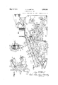
Figure 1 is a side elevation of the machine with the casing removed, the View showing particularly the controlling devices.
Fig. 2 is a detail rear elevation of certain of the control members shown in Fig. 1;
Fig. 3 is a partial side elevation showing the mechanism for moving the registers into and out of engagement with the actuator racks;
Fig. 4 is a side elevation and section showing how the duplex registers are associated with the other mechanism of the machine;
Fig. 5 is a partial side elevation and section of one of the registers and its transfer mechanism, the view showing the register in engagement with the actuator racks and the transfer mechanism in the position it occupies after an initial carry has occurred;
. Fig. 6 is a view similar to Fig. 5, the counter being shown out of engagement with the racks and the transfer mechanism in the position it occupies after a transfer has been effected;
Fig. 7 is a detail side elevation of the controls for the duplex registers, the parts being shown in the position they occupy when the lower register is being used;
Fig. 8 is a detail side elevation similar to Fig. 14 showing the parts in the position they occupy when the upper register is being used;
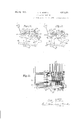
Fig. 9 is a detail side elevation of the con trols including certain connections operated by the total and sub-total keys;
Fig. 10 is a detail side elevation showing the character printing controls including the connections operated by the non-add key;
Figs. 11, 12, 13 and 14: are detail side views of the controls for character printing;
Fig. 15 is a top plan view of a portion of the duplex register section.
No attempt will be made in this case to use the same reference numerals as were used in the parent case because the reference numerals in that case were necessarily of high order, that is, they began with 236. The present description and drawings can be simplified by using reference numerals of lower order and this will be done.
General construction Referring to Fig. 4:, the machine includes a keyboard provided with a plurality of depressible amount keys 21 which, when depressed, act as stops for diiierential stop bars 22 that are urged forwardly by springs 23. There are a plurality of rows of these devices but only one now will be described. The stop bar 22 is connected at its rear ends to the arm 24 of an actuator rack25. Connected to the actuator rack 25 is a type bar 26 adapted to be thrown into printing engage ment with a paper on a platen 27 by means of a hammer mechanism 28.
When the machine is given a stroke of operation, a main shaft 30 is first rocked counterclockwise during the forward stroke of the machine and then returned clockwise during the return stroke. This also rocks the operating cam 31 in like manner. As the cam moves counterclockwise from its Fig. lposition, it releases a roller'32 on the end of an arm 33 connected to a bail 34; that normally engages the actuator racks 25 to hold them in their normal position. When the roller 32 is released, a spring 35 swings the arm 33 and hail 3d counterclockwise and releases theactuator racks whereupon these racks to gether with the stop bars 22 are moved forward by their springs23 until arrested in differential positions by depressed amount reys.
Upon the return stroke of the machine, the drive shaft 30 is rocked clockwise where upon the cam 31 engages the roller 32 and tit) iltllll rocks the bail 34 clockwise to return the actuator racks from their differential positions to their normal positions.
Duplex registers The machine is provided with two registers, the upper one being numbered 40 and the lower one 50. These registers and their transfer mechanisms are similar in construction and operation and, in order to simplify the description, only the upper one will be described, it being understood that the lower one is of the same construction.
Referring to Fig. 3 the register 40 comprises a plurality of toothed pinions rotatably mounted on a shaft 41 supported by the arms 42 of a yoke which rocks with a shaft 43 to rock the register into and out of engagement with the actuator racks 25. A cam 44 is provided for controlling the movement of the register, said cam being carried on one arm of a yoke 45 rocked with the shaft 46 in a manner hereafter described. The edge of the cam 44 bears against a roller 47 on the end of shaft 41, the roller being urged into engagement with the edge of the cam by a spring 48.
The lower register 50 is mounted and controlled in the same way by a cam 51 rocking with a shaft 52.
Cooperating with each register is a transfer mechanism, one of said mechanisms being shown in detail in Figs. 5 and 6. It comprises a transfer segment 53 normally latched against movement in a clockwise direction by a latch 54. A trip pawl 55 is provided adapted to be swung clockwise by a transfer projection on a corresponding pinion of the register. When the pawl is moved clockwise to the position of Fig. 5 it is latched in this position by a latch 56. When the register is moved out of engagement with the actuator racks and into engagement with the transfer segments, the latched pawls 55 move with the register and engage the latches 54 to release them thereby permitting the transfer segments to effect carries in the orders in which such carries should be effected. An understanding of the details of the transfer mechanism is not necessary for the present case, said transfer mechanism being fully described in Patent No. 1,781,179.
Selective control of the registers Either or both of the registers may be brought into engagement with the actuator racks by means of a main pitman operating under the control, in the embodiment illustrated, of a lever 61 as will now be described.
The pitman 60 (Fig. 1) is mounted to slide back and forth on one of the side plates of the machine, the pitman being supported at its front end by a stud 62 and at its rear end by a stud 63. The forward end of the pitman is forked or U-shaped and pivoted to the upper arm 64 of the U is a shouldered pawl 65 urged to the position of Fig. 1 by a spring 66. Pivoted on the lower arm 67 of the pitman is a pawl 68 controlled by the total and subtotal keys as will be later described. The lower arm of the pitman has a hook-shaped end 69 for a purpose that will presently appear..
Reciprocation of the pitman 60 is effected by studs 70 and 71 on a plate that rocks with the main drive shaft 30 of the machine.
In normal operation, the parts are in the position of Fig. 1. The pawl 68 is out of the path of the stud'7 j" and there is nothing in the path of the stud 71. Accordingly, as the main drive shaft 30 rocks counterclockwise neither of the studs 70 or 71 have any action in moving the pitman 60. Near the end of the forward stroke of the machine the stud 71 moves behind the shoulder on the pawl 65 and, upon the return stroke of the machine, this stud engages the shoulder on the pawl 65 to move the pitman 60 rearward. As will be described later, this results in rocking one or both of the registers into engagement with the actuator racks prior to the descent of the latter so that addition may be performed.
\Vhile the pitman 60 thus serves to move the registers, the selection of which register shall be moved isunder the control of a lever 61.
Referring to Figs. 7 and 8, it will be observed that two V-shaped members are pivoted to the right hand end of pitman 60, each of said members having one long and one short arm. One member has an up r long arm 72 and a lower short arm 73. he other member has a lower long arm 74 and an upper short arm 75. The two short arms are connected by a spring 7 6'.
The upper long arm 72 has a slot 77 in its outer end and ahook-shaped projection 78 adapted to engage over a stud 79 on an arm 80 of a yoke 45 which moves the operating cam 44 for the upper register.
The lower arm 74 has a slot 81 in its outer end and a hooked shaped projection 82 adapted to engage over a stud 83 on an arm 84 of the yoke 85 that rocks the operating cam 51 for the lower register.
When the parts are in the position of Fig. 7 the lower long arm 74 is hooked to the operating cam for the lower register so that, when the pitman 60 is moved, the lower register will be moved while the upper register remains stationary.
When the parts are in the position of Fig. 8 the upper long arm 72 is hooked to the operating cam for the upper register so that, when the pitman 60 is moved, the upper register will be moved while the lower register will remain stationary.
The position of these arms 72 and 74 is controlled by the lever 61. Connected to the lever 61 is a link 86 having a stud 87 near its front end. (Jo-operating with this stud is a spring pressed detent 88 that serves to hold the lever 61 in any one of the three positions to which it may be moved. The rear end of the link 86 is connected to one arm of a three armed lever 90 pivoted at 91. The rearwardly extending arm 92 of this lever 90 carries a stud 93 positioned to engage the inner edges of the short arms 73 and 75.
When the lever 61 is in its intermediate position, as shown in Fig. 1, the stud 93 is midway between the short arms 73 and 75. At that time the spring 76-tends to bring the arms 73 and 75 together which swings the long arms 72 and 74 outwardly to the position of Fig. 1 so that both of. these long arms are hooked to the operating cams for their registers. Accordingly, when the control lever 61 is in its intermediate position, both of the register operating cams are connected to the pitman 60 so that, when the pitman is moved, both registers will be moved.
When the control lever 61 is pulled forward to the position of Fig. 7, the threearmed lever 90 is rocked clockwise and the stud 93 contacting the arm 73 swings this arm clockwise which carries the long arm 72 to the position of Fig. 7 so that stud 79 is out of slot 77. The downward movement of arm 7 3 tensions the spring 76 which, of course, tends to urge the long arm 74 more firmly into engagement with its stud 83. With the parts in this position the lower register operating cam is connected to pitman 60 but the upper register cam is not.
When the control lever 61 is pushed rearward to the position of Fig, 8, the threearmed lever 90 is rocked counterclockwise and the stud 93 forces the short arm 75 upward which swings the long arm 74 upward to the position of Fig. 8 where the slot 81 is moved away from the stud 83. The spring 76 is again tensioned but, this time, it tends to urge the long arm 72 into engagement with the stud 79. With the parts in this position, the upper register operating cam is connected to the pitman 60 and the lower register operating cam is disconnected.
Suitable interlocking means is provided for preventing movement of the lever 61 after a machine operation has started. As the machine is operated the end of a shaft 94 shown in Fig. 1 moves either above or below an arm 95 integral with lever 61 or it moves into a slot 96 in the end of said arm, depending on whichof its three positions the lever 61 occupies. This prevents movement of the lever after operation of the machine has started- This interlocking device not only prevents movement of the lever 61 while the machine is in operation but it prevents operation of the machine if the lever 61 is not in correct position. Should the lever 61 not be in correct position the end of the shaft 94 will engage the edge of the arm 95 which causes the driving means of the machine to be disconnected from the operating mechanism as is described in the parent application.
Totals and subtotals When a .total is, taken, the register from which it is taken must be moved into engagement with the actuator racks before they ascend so that the register will control the differential positions to which the racks move, the register pinions being arrested in their zero position. If the register is to be cleared after the taking of a total it is .moved out of engagement with the actuator rack prior to the descent of the latter. On the other hand, if only a subtotal is to be taken the register is allowed to remain in engagement with the racks so that, during their descent, the pinions are returned to the position they occupieil immediately before the taking of a subtcta v The total key T (Fig. 1), has a stem positioned to engage the edge of a pivoted lever 100 carrying a stud 101 engaging a yielding slide 102 connected to the pawl 68 so that, upon depression of the total key, the pawl 68 is rocked clockwise into the path of the stud 70. At the same time the lever 100 engages an arm 103 pivoted on the pitman 60. This arm has a hook shaped end 104 which is moved into the path of the stud 71. It also has a central projection 105 for disabling pawl 65.
With the parts in the position of Fig. 1, depression of the total key and operation of the machine causes the following action to take place. At the beginning of the forward stroke the stud engages the end of the pawl 68 and moves the pitman 60 rearwardly which causes the register connected with the pitman to be rocked into engagement with the actuator racks. At the end of the forward stroke the stud 71 engages the hooked end 104 of the arm 103 and pulls the pitman 60 forwardwhich rocks the register out of engagement with the actuator racks. Upon the return stroke, the pawl 65 having been disabled by projection105, no further movement of pitman 60 takes place. Stud 70 does not engage the hooked end 69 of the lower arm 67 of the pitman because the pitman has already been moved forward.
When the subtotal key ST is depressed, it engages the end of a pivoted member 106 which engages the end of the linkage 102 to rock the pawl 68 clockwise. It is to be noted that the depression of the subtotal key does not move the arm 103 and hence does not disable pawl 65.
When the subtotal key is depressed and the machine operated the parts operate as follows At the beginning of the forward stroke. the stud 70 engages the end of pawl 68 and moves the pitman rearwardly which rocks the register connected to the pitman into engagement with the actuator racks. At the end of the forward stroke, the stud 71 does not engage the hooked end 104 of the arm 103 and the pitman 60 remains in its rearward position. At the beginning of the return stroke, stud 71 would engage pawl except for the fact that the pitman is already in its rear position so that the pawl is out of the path of the stud. Accordingly, thepitman remains in its rear position until near the end of the return stroke when the hooked end 69 of the lower branch 67 of the pitman is engaged by stud 70, whereupon the pitman is pulled forward to rock the register out of engagement with the actuator racks.
A total or a subtotal may be taken from either register depending upon the position of the control lever 61. If this control lever is in a position to render the upper register active and the lower register inactive, the total or subtotal will be taken from the upper register. If, on the other hand, the lever 61 is in position to render the lower register active and the upper register inactive, the total or subtotal will be taken from the lower register.
If the control lever 61 is in its intermediate position so that both registers are active, provision is made to cause the total or subtotal to be automatically taken from the lower register. In order that this result may be accomplished, the following construction has been provided:
Pivoted at the lower rear corner of the machine, as shown in Fig. 1, is a long arm having an upstanding lug 111 at its forward end. At the center of this long link is a downwardly extending cam projection 112 (Fig. 9) adapted to rest on a stud 113 on one arm of a member 114 pivoted at 115 toth e three armed lever 90. The member 114 has another arm 116 provided with a stud 117 positioned over the upper edge of the short arm 73 of one of the V-shaped members pivoted to the pitman 60.
When the control lever 61 for the two registers is in its central position so that both registers are active, the cam projection 112 of the link 110. rests on the stud 113% shown in Fig. 9. If, with the parts in this position, the total or the subtotal key is depressed, the levers 100 or 106 as the case may be will be rocked counterclockwise. Both of the levers 100 and 106 have portions positioned to engage the lug 111 on link 110. Depression of either of these keys will swing the link 110 counterclockwise. This rocks the member 1l4116 clockwise and forces the arm 73 downward. which forces the long arm 72 down to disconnect it from the upper register controlling cam. Accordingly, the act of pressing the total or subtotal key, with the lever 61 in central position, acts to automatically disconnect the upper register and leaves the lower register in condition so that the total or subtotal will be taken from it.
When the total or subtotal keys are released and returned to normal in the usual manner at the end of the totalizing or subtotaling operations of the machine, the link 110 is released, whereupon it is returned to normal by the spring 76 acting on arm 73, stud 117, bell crank 116--114 and stud 113. This action of spring 76 also returns the V- shaped member 7372 to register-connecting position so that, at the end of the totaling or subtotaling operation, the machine is in condition again for both of the registers to be active during item entering operations. In other words, when the machine is conditioned to re ister items on both registers, a total or su total can be taken from one of the registers by simply depressing the total key and operating the machine, after which items can be entered in both registers again without changing the condition of the register controlling means.
When the control lever 61 is swung either forwardly or backwardly from its central position, the three armed lever 90 is moved from its Fig. 9 position either forward or backward and the member 114 is carried with it so as to remove the stud 113 from under the 'cam projection 112 on link 110. This allows the link to drop so that its lug 111 is out of the path of the levers that are rocked by the total and subtotal keys. Accordingly, when the control lever 61 for the registers is in either its upper or its lower register position, the automatic control above described is disabled.
Character printing It is desirable to print characters indicating in which register items have been entered and also indicatingthe character of the calculation that has occurred in each register. Character printing devices have been provided for accomplishing this purpose.
A special actuator segment and type bar (not shown) is provided, these parts being of the same construction as corresponding parts illustrated in Fig. 4. The character printing actuator rack and type bar, instead of being controlled by a stop bar and amount keys, are controlled by an arm 120 (Fig. 10) of a yoke 121 having a second arm 122 provided with a slot engaging over a stud connected with the actuator rack. The position of the arm 120 is determined by stop arms controlled by various controlling keys and levers on the machine.
e will first explain the control of the character printing type bar by the lever 61 that controls which of the registers shall be active.
Referring to Fig. 10, it will be observed that the three armed lever 90, whose position is controlled by the link 86 operated by the lever 61 carries a stud 123 adapted to engage the end of an arm 124 of a yoke 125 pivoted at 126. This yoke has a forwardly extending irregular shaped arm 127 provided with various shoulders adapted to be engaged by a lateral lug 128 on the upper end of the'arm 120.
The arm 120 normally occupies a position clockwise from that shown in Fig. 10 with the lug 128 in the large U-shaped opening in the arm 127. When the machine is operated, the arm 120 is released so that it rock counterclockwise until its lug 128 engages one of the shoulders that is positioned to arrest it. This, of course, arrests the character printing type bar.
When the control lever 61 is in its position for using the lower register only, the three armed lever 90 is in a position slightly clockwise from the position of Fig. 10 and the yoke 125 with its member 127 occupies a position slightly clockwise from that shown. When the arm 120 is released, it is arrested immediately by the shoulder LA, meaning lower counter-addition.
The character type bar is not moved from normal position so that no character is printed. The operator knows that when no character is printed, the item is added in the lower counter.
When the control'lever'61 is moved to its intermediate position which renders both registers active, the three armed lever 90 is rocked to the position of Fig. 10 and the yoke 125 isrocked in the same direction so that the parts occupy the position of Fig. 10. When the arm 120 is released, it moves counter-clockwise until the .lug 128 strikes the shoulder 130. This arrests the character type bar in a position to print a character indicating that the item has been added on both registers.
When the control lever 61 is moved farther to the rear, that is, to the position for making the upper register active, the three armed lever 90 is rocked still farther counterclockwise which rocks the yoke 125 clockwise from the position of Fig. 10 to a position such that none of the shoulders on the member 127 are in the path of the lug 128 on arm 120. Accordingly, when the machine is operated and the arm 120 is released, the arm moves until it strikes a fixed stud 131 which arrests the character type bar in a position to print a character indicating that the item has been added on the upper register.
Sometimes items are not added in either register and it is desired to indicate this on the printed record. 7 The non-add key NA (Fig. 10) has a stem adapted engage a pivoted lever 132 whose outer end is enlarged and positioned to engage a projection 133 on the arm 127. When t e non-add key is depressed, the arm 127 is rocked counterclockwise to a position such that the shoulder NA. is in the path of the lug 128. With the parts in this position,-wh-en the machine is operated, the arm 120 moves forward a slight distance to a position such that the type bar is arrested in position to print a character indicating that an item has not been added in either register.
lVhen a total or subtotal is taken it is desirable to have the character indicate Whether the operation is a total or a subtotal and on which register it occurs.
it will be recalled that a total is taken from the lower register when the control lever 61 is in either its forward position for rendering only the lower register active or in its central position for causing both registers to be active. This fact must be kept in mind in considering the operation of the character printing mechanism.
When the total key is depressed, it rocks the lever 100 (Fig. 11) counterclockwise and the lower edge of this lever engages a lateral lug 134 10) on' the member 127. This inovesmember 127 to a position "such that none of its shoulders will interfere with the forward movement of the arm 120 and this occurs no matter whether the control lever 61 is in its forward or in its central position. The character printing is thus taken out of the control of the arm 127 and placed under the control of certain other stop arms positioned by the total and subtotal keys as follows:
The lever 100 that is rocked by depression of the total key is, in fact, one arm of a yoke 140 pivoted on the stud 141 shown in Fig. 2. This yoke has another short arm 142 11) which is positioned behind another yoke 143 that has a forwardly entendingstepped arm 144. The arm 144 is connected by a spring 145 to a projection 146 on a yoke 147 having a stepped arm 148. A spring 149 tends to hold both arms 144 and 148 in the position shown in Fig. 11. However, when the lever 100 is moved counterclockwise by depression of the total key, the short arm 142 ot the yoke 140 rocks the yoke 143 counterclockwise which rocks arm 144 downward. The arm 148 tends to follow but is arrested by the cam end 150 on a third arm 151 of the three armed lever 90. It will be recalled that the three armed lever 90 is positioned by the control lever61. When the control lever 61 for theregisters is in its lower register or its intermediate position, the cam surface 150 is under a portion of the yoke 147 and moviement of the yoke with its stop arm 148 is prevented. When the parts are in this position, if the total key is depressed, the arm 100 rocks the yoke 140 counterclockwise and this positions the stop arm 144 as shown in Fig. 13, the arm 148 being blocked against movement. This position of arm 144 positions the stop shoulder LT in the path of the lug 128 on arm 120 and, upon operation of the machine, said arm is stopped in the position to arrest the character type bar in a position to print a character indicating that a total has been taken from the lower register.
If a subtotal is taken from the lower register instead of a total, the controllever 61 being either in its forward or central position, the action is slightly diflerent and as follows:
Depression of the subtotal key ST moves the arm 106 counterclockwise. This arm is connected to a yoke 153 (Fig. 2) having a short arm 154 positioned behind yoke 143. The movement given yoke 143 by depression of the subtotal key is slightly more than when the total key'is depressed and it results in moving the stop arm 144 to the position shown in Fig. 12 where the shoulder LST is in the path of the lug on arm 120. The arm 148 is blocked against movement as previously described. The result is that the character printing type bar is arrested in the position to print a character indicating that the subtotal has been taken from the lower counter.
When a total is taken from the upper register the control lever 61 must be in its rear position and, when it is in this position, the three armed lever is rocked clockwise from its Fig. 11 iosition to" a position such that the cam nose 150 of arm 151 is not under the yoke 147. Accordingly, when the total ke is depressed and the arm with its yoke rocked counterclockwise, both of the stop arms 144 and 148 are rocked counterclockwise. Since the shoulders on the arm 148 are ahead of the shoulders on the arm 144, the arm 148 instead of arm 144 will be efl'ective to arrest the arm 120. The result is that the arm 120 is positioned so that the shoulder UT is in the path of the lug on arm 120 and the character printing type bar is arrested in a position to print a character indicating that a total has been taken from the upper register.
When a subtotal is taken from the upper register the parts operate as above described, except that the subtotal key positions the arms instead of the total key. When the subtotal key is depressed the arm 148 is moved counterclockwise slightly farther than in the case of a depression of a total key and the result is that the stop shoulder UST is positioned in the path of the lug on arm 120 so as to arrest the character printing type bar in a position to print a character indicating that a. subtotal has been taken from the upper counter.
The machine thus automatically indicates what transaction has taken place and in what register the operation has occurred. If it is'addition in the lower register, no character is printed. If it is addition in the upper register an appropriate character is is indicated. If a total is taken from a low-.
er register such fact is indicated regardless of whether the lever 61 is in its forward or central position. If a total or subtotal is taken from the upper register that fact is also shown.
What is claimed is:
1. A calculating machine having two registers, controlling means for conditioning said machine to render either or both of said registers active, a total taking means, and means controlled by said total taking means acting to automatically select a predetermined one of said registers for total taking when said total taking means is conditioned for total taking with said controlling means conditioned to render both of said registers active.
2. A calculating machine having two registers, a pitman adapted to be reciprocated by operation of the machine, separate connections for connecting said registers to said pitman, controlling means forrendering either or both of said connections effective, and total taking means having provisions for automatically disabling one of said connections when the total taking means is conditioned for total taking with the controlling means in position to render both connections effective.
3. A calculating machine having two registers, a pitman adapted to be reciprocated by operation of the machine, a connecting link between said pitman and one of said registers, a connecting link between said pitman and the other of said registers, controlling means for positioning said links to cause either or both of said registers to be connected to said pitman, and a total taking means having portions acting to automatically move one of said links to disable the connection to one register when the total taking means is manipulated to take a total while said controlling means is positioned to cause both registers to be connected to said pitman.
4. A calculating machine having two registers, a pitman adapted to be reciprocated by operation of the machine, a V-shaped link for connecting said pitman to one register, a second V-shaped link for connecting said pitman to the other register, a controlling means for engaging one set of arms of said V-shaped links to move either or both of said links to connected position, and a depressible total key having connections for moving one of said links upon depression of the total key when the controlling means is in position to cause both of said links to be in connected position.
5. A calculating machine having two registers, a pitman reciprocated by operation of said machine, a link for connecting said pitman to one register, a link for connecting said pitman to the other register, a manually III) movable means for positioning said links to *cause either or both of them to be: placed in .connected position, a member conditioned for operation by movement of said manually movable means to position for placing both of said links in connected position, and a total key and connections for operating said member to disable one of said links.
6. A calculating machine having amount keys, two registers, total taking means for said registers, controlling means for conditioning said machine to render either or both of said registers active to receive items entered on said amount keys, and means conditioned as an incident to taking a total from said machine with said total taking means, while said controlling means is conditioned to render both of said registers active, for automatically disabling one of said registers for total taking. y 1
7. A calculating machine having actuator racks, amount keys, two registers, a total taking means for said registers, separate connections for each register for controlling its movement into and outof engagement with said racks, controlling means controlling said register connections, said controlling means,
when in one condition, conditioning both of said register connections to cause both of said registers to engage said racks as the machine is operated to thereby enable both registers to receive items entered on said amount keys, and means conditioned as an incident to taking a total from said machine with said total taking means, while said controlling means is conditioned to cause both of said registers to engage said racks, acting to automatically disable one of said register connections. r
8. A calculating machine having amount keys, actuator racks, two registers, a total taking means for said registers, a reciprocable pitman reciprocated during each operation of the machine, separate connections between each of said registers and said pitman for moving the registers into and outof engagement with said racks, controlling means for said connections for selectively placing either or both of said connections in condition to cause either or both of said registers to engage said racks'to receive items entered on said amount keys, and means conditioned as an incident totaking a total from said machine with said total taking means, while said controlling means is conditioned to render both of said register connections operable, acting to automatically disable one of said connections.
9. A calculating machine having amount keys upon which itemsmay be entered, two
registers, register controlling means for conditioning said machine to cause bath of said registers to be rendered active during item entering operations, total taking means for taking totals from said registers, and means controlled as an incident to the taking of a total with said total taking means, while said controlling means is conditioned to render both of saidregisters active, for automatically causing said total to be taken from one of said registers and the other to be rendered inactive.
10. A calculating machine having amount keys, two registers, a total taking means for taking totals from said registers, register controlling means for conditioning the machine to cause both of said registers to be rendered active during item entering operations, and means acting as an incident to the taking of a total with said total taking means while said controlling means is conditioned to render both registers active for automatically causing a total to be taken from one of said registers and the other to be temporarily rendered inactive, said incidental means, after said totaling operation, leaving said machine in condition for both registers to be rendered active during item entering operations, to thereby enable items entered on said amount keys to be again entered in both registers without changing the condition of said controlling means.
11. A calculating machine having amount keys, actuator racks, two registers, means for causing engagements between said racks and registers for item entering and totaling operations, controlling means for conditioning the machine to cause engagements between both of said registers and racks during item entering operations whereby items entered on said amount keys will be entered in both registers, total taking means for taking totals from said registers, and means acting as an incident to the taking of a total with said total taking means while said controlling means is conditioned to cause engagement between both of said registers and said racks for preventing engagement between one of said registers and said racks during said total taking operation, said incidental means, after said total taking operation, leaving said machine in condition to enable engagements to take place between both of said registers and said racks during item entering operations whereby items entered on said amount keys subsequent to said total taking operations may be entered in both registers without changing the condition of said controlling means.
In witness whereof, we have signed our names this 18th day of February, 1931.
[L. 5.] KATHLEEN H. HORTON,
. And DETROIT TRUST COMPANY, Successor to Detroit a? Security Trust Company, Ea:-
eeutors under Will of Allen A. Horton, Deceased,
By SELDEN B. DAUIE,
Vice President, JOHN J. SPOUTZ, Assistant Secretary.
Publications (1)
| Publication Number | Publication Date |
|---|---|
| US1908358A true US1908358A (en) | 1933-05-09 |
Family
ID=3425174
Family Applications (1)
| Application Number | Title | Priority Date | Filing Date |
|---|---|---|---|
| US1908358D Expired - Lifetime US1908358A (en) | And detroit totst cqwpawz |
Country Status (1)
| Country | Link |
|---|---|
| US (1) | US1908358A (en) |
Cited By (3)
| Publication number | Priority date | Publication date | Assignee | Title |
|---|---|---|---|---|
| US2647687A (en) * | 1953-08-04 | Calculating machine | ||
| US2650765A (en) * | 1953-09-01 | Chi liang cho | ||
| US2760722A (en) * | 1956-08-28 | Two-total credit balance adding |
-
0
- US US1908358D patent/US1908358A/en not_active Expired - Lifetime
Cited By (3)
| Publication number | Priority date | Publication date | Assignee | Title |
|---|---|---|---|---|
| US2647687A (en) * | 1953-08-04 | Calculating machine | ||
| US2650765A (en) * | 1953-09-01 | Chi liang cho | ||
| US2760722A (en) * | 1956-08-28 | Two-total credit balance adding |
Similar Documents
| Publication | Publication Date | Title |
|---|---|---|
| US2221861A (en) | Calculating machine | |
| US2397745A (en) | Adding machine | |
| US1854875A (en) | M white | |
| US1957501A (en) | Method and means for obtaining true | |
| US2118588A (en) | Calculating machine | |
| US2308940A (en) | Tens transfer mechanism for | |
| US1908358A (en) | And detroit totst cqwpawz | |
| US2226960A (en) | Accounting machine | |
| US2240797A (en) | Calculating machine | |
| US2745601A (en) | Key-responsive calculating machine | |
| US2821342A (en) | Capellaro | |
| US2754052A (en) | Capellaro | |
| US3092313A (en) | Register | |
| US3009634A (en) | Allward | |
| US1909715A (en) | pasinski | |
| US2364769A (en) | Accounting machine | |
| US2255557A (en) | Totalizer selecting mechanism fob | |
| US1844070A (en) | muller | |
| US2269931A (en) | Calculating machine | |
| US1992142A (en) | Calculating machine | |
| US1914401A (en) | Calculating machine | |
| US3023951A (en) | Control apparatus for accounting machines | |
| US2285311A (en) | Accounting machine | |
| US2308292A (en) | Computing machine | |
| US2692726A (en) | Calculating machine function |