US1908331A - Radiator shield or cover - Google Patents
Radiator shield or cover Download PDFInfo
- Publication number
- US1908331A US1908331A US634594A US63459432A US1908331A US 1908331 A US1908331 A US 1908331A US 634594 A US634594 A US 634594A US 63459432 A US63459432 A US 63459432A US 1908331 A US1908331 A US 1908331A
- Authority
- US
- United States
- Prior art keywords
- radiator
- plates
- parts
- cover
- straps
- Prior art date
- Legal status (The legal status is an assumption and is not a legal conclusion. Google has not performed a legal analysis and makes no representation as to the accuracy of the status listed.)
- Expired - Lifetime
Links
Images
Classifications
-
- F—MECHANICAL ENGINEERING; LIGHTING; HEATING; WEAPONS; BLASTING
- F24—HEATING; RANGES; VENTILATING
- F24D—DOMESTIC- OR SPACE-HEATING SYSTEMS, e.g. CENTRAL HEATING SYSTEMS; DOMESTIC HOT-WATER SUPPLY SYSTEMS; ELEMENTS OR COMPONENTS THEREFOR
- F24D19/00—Details
- F24D19/06—Casings, cover lids or ornamental panels, for radiators
-
- F—MECHANICAL ENGINEERING; LIGHTING; HEATING; WEAPONS; BLASTING
- F24—HEATING; RANGES; VENTILATING
- F24D—DOMESTIC- OR SPACE-HEATING SYSTEMS, e.g. CENTRAL HEATING SYSTEMS; DOMESTIC HOT-WATER SUPPLY SYSTEMS; ELEMENTS OR COMPONENTS THEREFOR
- F24D2220/00—Components of central heating installations excluding heat sources
- F24D2220/20—Heat consumers
- F24D2220/2009—Radiators
- F24D2220/2018—Column radiators having vertically extending tubes
Definitions
- My invention relates to a shield or screen for radiators, and the principal object of the invention is to provide a preferably metallic n screen to cover the front of a radiator, and
- L composed of telescopically associated parts adjustable to the length of the radiator, and provided with means for quickly and securely attaching theparts-in place on the front of the radiator.
- top covers of known type N may then be positioned on top of the radiator to complete the appearance of the screen Vas a unitary device and to conceal the top edges and fastening means on the ⁇ front plates, as shown in the accompanying drawing, wherein Y Fig. 1 is a perspective view of a radiator with top and front shields embodying my invention applied; i
- Fig. 2 is a sectional view on the line 2-2 d of Fig. 1;
- Fig. 3 is a sectional view on the line 3-3 of Fig. 1.
- the numeral 5 designates generally the top cover composed of the parts 6 and 7 having depending flanges 8 and 9 respectively.
- the flanges 9 on the part 7 slidably fit within channels provided by bending up the ends 11 of the flanges 8.
- the top cover may be adjusted to t radiators of different lengths.
- the front shield or screen constructed in accordance with my invention comprises the two sheets 12 and 13 preferably formed of sheet metal and one of which, the sheet 13 as shown in the drawing, has its top and bottom ends bent as indicated at 14C to pro- Referring to Fig. 3, it will be noted that vide channels to receive the edges of the other part or sheet 12, so that they telescopicallyv interfit andimay be longitudinally adjusted the same as the top 5.
- Each of the parts 11 and 12 has its free end bent or flanged yas indicated at 15 to abut the ends of the radiatorvl() whereby the parts may be readily adjusted to the right length simply by sliding them together until the flanges 15 abut theends of the radiaton.
- top straps 16 which may be formed as individual elements and furnished flat.
- the straps are of pliant metal so that they may beA bent at the proper points along the proper lines at the front and back edges of the topA to span the radiator.
- the straps y16 are provided with openings to register -with openings in the parts 12'and 13, so that screws or bolts 17 i7 may be inserted through the openings to se- Y cure the straps 16to the respective parts of thev front screen or shield.
- Each 'of the .straps 16 is preferably of such a length that .after they have been bent down at the back of the radiator there will be a portion as indicated at 20, disposed at and against the back to hold the parts 12 and 13 up in proper position.
- I provide side straps 18 which may 8.9 be attached to the sides or flanges 15 by means of screws or bolts 19 passing through registering openings in the straps and sides or flanges 15.
- the straps 18 are of suflicient length to extend across the width of the radiator and to be bent around one of the pipes as indicated at 20.
- Vhile I have shown the several parts assembled and properly ⁇ formed, in which manner they may be furnished, I wish it to PP be understood that I may make the straps and partsv 12 and 13 all perfectly flat. ⁇
- the registering openings for the bolts ⁇ are formed in the straps and plates, and the bolts themselves may ⁇ be furnished so that(l the 4straps can be secured to the parts theyv are to support. It would be necessaryfor the user, under such conditions to bendy the straps along the proper lines to make them spairthe top of the radiatoruand engageloo of various depths around the sides or ends of the radiator in the manner shown.
- the parts can be packaged in compact form for shipping and merchandising.
- the top 5 is placed on and conceals the top straps which also provide .a flat support for the top. Vhen the top is adjusted to the proper length the points Where the parts 6 and 7 overlap will be substantially in alinement with the points where parts 12 and 13 overlap as shown in the drawing. This is due to the tact that parts 6 and 12, and 7 and 13, respectively, are preferably the same length.
- the complete assembly of the front and top shields resembles, from the front, a unitary casing as the front skirt 8 on the top overlaps the top edges ot the front screen parts and conceals the front edge of the top of the radiator and the straps 16. lf the topsof the radiator coils are curved the straps may be bent to form fiat supporting surfaces for parts 6 and 7.
- the front plates ' can be made of dimensions from top to bottom according to standard types of radiators and of lengths such that they can v5()4 overlap to fit the smaller sizes or be extended to fit lono'er sizes. Due to the fact that the securing means provided in accordance with 'my invention are adaptable by the user to radiators of various thicknesses, the invention provides a cover or shield which can be adaptedv not only to radiators of various lengths and ⁇ lheights but also to radiators I claim:
- a radiator screen comprising front plates slidably connected for longitudinal movement relative to each other for adjustment to thelength of the radiator, means connected to the top of each of said plates to plates on the front of the radiator, a pair of slidably connected top members to cover the top of the radiator and said means, the said top members which are superposed above the respective front plates being of the same length as said plates whereby said plates and members will terminate in substantially the same planes.
- a screen of the character described comprising a pair of plates to cover the front of a radiator, means on said plates to span the top of the radiator to hold the plates in position on the front, and a top cover for the radiator, said means constituting supports on which the top rests.
- a screen of the character described comprising a pair of plates slidably connected for movement relative to each other for adjustment tothe length of the radiator, means connected to the top of said plates to span the top of the radiator to hold the plates in position on the front of the radiator, said means comprising flat metallic strips connected to the top edges of the front of the plates, and a top cover for the radiator having a front skirt to overl'ap'the top edges of the plates, said strips affording substantially Hat surfaces on which the top 'may rest.
- a screen or shield for radiators comprising a pair ot plates connected for longitudinal movement relative to each other for adjustment relative to the length of the radiator, a pair of elongated bendable strips connectedA with each of said plates adjacent their top edges, said strips being of sulicient length to extend across and partially behind the radiator to hold the said plates at the iront ot' the radiator, and a second pair of strips connected to the ends of said plates and bendable around the ends of the radiator to hold the plates against movement away ⁇ from the radiator'.
- a shield or screen for radiators comarising a pair of plates slidably connected for adjustn'ient longitudinally ofthe Aradiator, each of said plates having on one end a flange to abut the ends of the radiator,
Landscapes
- Engineering & Computer Science (AREA)
- Physics & Mathematics (AREA)
- Thermal Sciences (AREA)
- Chemical & Material Sciences (AREA)
- Combustion & Propulsion (AREA)
- Mechanical Engineering (AREA)
- General Engineering & Computer Science (AREA)
- Baking, Grill, Roasting (AREA)
Description
May 9, 1933- A. EHRAMJIAN RADIATOR SHIELD OR COVER Filed Sept. 25. 1932 M R. mw mM VA mw ATTORNEY Patented May 9, 1933 ARAM EHRAMJIAN, or envenena, NEW YORK RADIATOR SHIELD on COVER Application led September 23, 1932. Serial No. 634,594.
\ My invention relates to a shield or screen for radiators, and the principal object of the invention is to provide a preferably metallic n screen to cover the front of a radiator, and
L composed of telescopically associated parts adjustable to the length of the radiator, and provided with means for quickly and securely attaching theparts-in place on the front of the radiator.
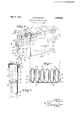
.1".3 As will be pointed -out in detail hereinafter, when the parts are properly adjusted to the length of the radiator and secured in place on its front, top covers of known type N may then be positioned on top of the radiator to complete the appearance of the screen Vas a unitary device and to conceal the top edges and fastening means on the` front plates, as shown in the accompanying drawing, wherein Y Fig. 1 is a perspective view of a radiator with top and front shields embodying my invention applied; i
Fig. 2 is a sectional view on the line 2-2 d of Fig. 1; and
Fig. 3 is a sectional view on the line 3-3 of Fig. 1.
Referring to the drawing, the numeral 5 designates generally the top cover composed of the parts 6 and 7 having depending flanges 8 and 9 respectively. The flanges 9 on the part 7 slidably fit within channels provided by bending up the ends 11 of the flanges 8. Thus the top cover may be adjusted to t radiators of different lengths.
- 373 -The top cover per se is not new. However,
when theV front of the radiator is to be obscured from view the usual manner of accomplishing this has been to provide a coml] lete enclosure of box-like construction having front, top, and end walls. Such structures are notV only expensive but are not portable, and occupy considerable 'space in shipping and storing.
the front shield or screen constructed in accordance with my invention comprises the two sheets 12 and 13 preferably formed of sheet metal and one of which, the sheet 13 as shown in the drawing, has its top and bottom ends bent as indicated at 14C to pro- Referring to Fig. 3, it will be noted that vide channels to receive the edges of the other part or sheet 12, so that they telescopicallyv interfit andimay be longitudinally adjusted the same as the top 5. Each of the parts 11 and 12 has its free end bent or flanged yas indicated at 15 to abut the ends of the radiatorvl() whereby the parts may be readily adjusted to the right length simply by sliding them together until the flanges 15 abut theends of the radiaton.
In orderto secure the front screen on the radiator, Igprovide top straps 16 which may be formed as individual elements and furnished flat., In such case the straps are of pliant metal so that they may beA bent at the proper points along the proper lines at the front and back edges of the topA to span the radiator. The straps y16 are provided with openings to register -with openings in the parts 12'and 13, so that screws or bolts 17 i7 may be inserted through the openings to se- Y cure the straps 16to the respective parts of thev front screen or shield. Each 'of the .straps 16 is preferably of such a length that .after they have been bent down at the back of the radiator there will be a portion as indicated at 20, disposed at and against the back to hold the parts 12 and 13 up in proper position. To further secure the screen in place, I provide side straps 18 which may 8.9 be attached to the sides or flanges 15 by means of screws or bolts 19 passing through registering openings in the straps and sides or flanges 15. The straps 18 are of suflicient length to extend across the width of the radiator and to be bent around one of the pipes as indicated at 20. L
. Vhile I have shown the several parts assembled and properly` formed, in which manner they may be furnished, I wish it to PP be understood that I may make the straps and partsv 12 and 13 all perfectly flat.` Of course, the registering openings for the bolts` are formed in the straps and plates, and the bolts themselves may `be furnished so that(l the 4straps can be secured to the parts theyv are to support. It would be necessaryfor the user, under such conditions to bendy the straps along the proper lines to make them spairthe top of the radiatoruand engageloo of various depths around the sides or ends of the radiator in the manner shown. Thus the parts can be packaged in compact form for shipping and merchandising.
In use, after the front shield has been applied as above described and shown in the drawing, the top 5 is placed on and conceals the top straps which also provide .a flat support for the top. Vhen the top is adjusted to the proper length the points Where the parts 6 and 7 overlap will be substantially in alinement with the points where parts 12 and 13 overlap as shown in the drawing. This is due to the tact that parts 6 and 12, and 7 and 13, respectively, are preferably the same length. Thus a neat appearance is had with a very cheap but effective arrangement and the complete assembly of the front and top shields resembles, from the front, a unitary casing as the front skirt 8 on the top overlaps the top edges ot the front screen parts and conceals the front edge of the top of the radiator and the straps 16. lf the topsof the radiator coils are curved the straps may be bent to form fiat supporting surfaces for parts 6 and 7.
I have shown the front skirt of the top provided` with heat escapement openings arranged in a decorative or orderly manner. The same scheme is preferably carried out Aon the parts 12 and 13 with the openings on all parts at regular intervals, so that when'the respective parts are properly adjusted on the radiator the groups of openings on the top cover and the front screen will be in alinement, thus enhancingv the unitary appearance of the structure.
So 'far as T am aware, front sheetsor plates for association with radiators and existing top covers in the-manner above specilied have never been known or used, and under my invention the same can be readily and cheaply made and sold either as an independent unit or in conjunction with top covers.
It should be understood that the front plates 'can be made of dimensions from top to bottom according to standard types of radiators and of lengths such that they can v5()4 overlap to fit the smaller sizes or be extended to fit lono'er sizes. Due to the fact that the securing means provided in accordance with 'my invention are adaptable by the user to radiators of various thicknesses, the invention provides a cover or shield which can be adaptedv not only to radiators of various lengths and` lheights but also to radiators I claim:
1. A radiator screen comprising front plates slidably connected for longitudinal movement relative to each other for adjustment to thelength of the radiator, means connected to the top of each of said plates to plates on the front of the radiator, a pair of slidably connected top members to cover the top of the radiator and said means, the said top members which are superposed above the respective front plates being of the same length as said plates whereby said plates and members will terminate in substantially the same planes.
2. A screen of the character described comprising a pair of plates to cover the front of a radiator, means on said plates to span the top of the radiator to hold the plates in position on the front, and a top cover for the radiator, said means constituting supports on which the top rests.
3. A screen of the character described comprising a pair of plates slidably connected for movement relative to each other for adjustment tothe length of the radiator, means connected to the top of said plates to span the top of the radiator to hold the plates in position on the front of the radiator, said means comprising flat metallic strips connected to the top edges of the front of the plates, and a top cover for the radiator having a front skirt to overl'ap'the top edges of the plates, said strips affording substantially Hat surfaces on which the top 'may rest.
1. A screen or shield for radiators comprising a pair ot plates connected for longitudinal movement relative to each other for adjustment relative to the length of the radiator, a pair of elongated bendable strips connectedA with each of said plates adjacent their top edges, said strips being of sulicient length to extend across and partially behind the radiator to hold the said plates at the iront ot' the radiator, and a second pair of strips connected to the ends of said plates and bendable around the ends of the radiator to hold the plates against movement away `from the radiator'. l
5. A shield or screen for radiators comarising a pair of plates slidably connected for adjustn'ient longitudinally ofthe Aradiator, each of said plates having on one end a flange to abut the ends of the radiator,
a pair of bendable metallic strips connected` to the top edges of each'ot the plates to span the top of the radiator, and a pair of bendable metallic strips connected to the said flanges and bendable around the rsides of the radiator. f
` Signed at Brooklyn, in the county of Kings and Stat-e Aof New York this 21st day of September A. D. 1932.
ARAM EHRAMJ IAN.
*span the top of the radiator to hold the
Priority Applications (1)
| Application Number | Priority Date | Filing Date | Title |
|---|---|---|---|
| US634594A US1908331A (en) | 1932-09-23 | 1932-09-23 | Radiator shield or cover |
Applications Claiming Priority (1)
| Application Number | Priority Date | Filing Date | Title |
|---|---|---|---|
| US634594A US1908331A (en) | 1932-09-23 | 1932-09-23 | Radiator shield or cover |
Publications (1)
| Publication Number | Publication Date |
|---|---|
| US1908331A true US1908331A (en) | 1933-05-09 |
Family
ID=24544440
Family Applications (1)
| Application Number | Title | Priority Date | Filing Date |
|---|---|---|---|
| US634594A Expired - Lifetime US1908331A (en) | 1932-09-23 | 1932-09-23 | Radiator shield or cover |
Country Status (1)
| Country | Link |
|---|---|
| US (1) | US1908331A (en) |
Cited By (5)
| Publication number | Priority date | Publication date | Assignee | Title |
|---|---|---|---|---|
| US4250954A (en) * | 1979-09-13 | 1981-02-17 | Remlinger George W | Heat control member and method |
| EP0196057A3 (en) * | 1985-03-27 | 1987-07-29 | Buchtal Gesellschaft Mit Beschrankter Haftung | Cover lid for a radiator |
| US6105668A (en) * | 1997-09-10 | 2000-08-22 | Behr Gmbh & Co. | Stacking-disk heat exchanger |
| ITTO20120975A1 (en) * | 2012-11-09 | 2013-02-08 | Trafilplast S N C | SAFETY BARRIER OF THERMAL PROTECTION. |
| US10407013B1 (en) | 2018-07-18 | 2019-09-10 | Denso International America, Inc. | Radiator core stone guard |
-
1932
- 1932-09-23 US US634594A patent/US1908331A/en not_active Expired - Lifetime
Cited By (5)
| Publication number | Priority date | Publication date | Assignee | Title |
|---|---|---|---|---|
| US4250954A (en) * | 1979-09-13 | 1981-02-17 | Remlinger George W | Heat control member and method |
| EP0196057A3 (en) * | 1985-03-27 | 1987-07-29 | Buchtal Gesellschaft Mit Beschrankter Haftung | Cover lid for a radiator |
| US6105668A (en) * | 1997-09-10 | 2000-08-22 | Behr Gmbh & Co. | Stacking-disk heat exchanger |
| ITTO20120975A1 (en) * | 2012-11-09 | 2013-02-08 | Trafilplast S N C | SAFETY BARRIER OF THERMAL PROTECTION. |
| US10407013B1 (en) | 2018-07-18 | 2019-09-10 | Denso International America, Inc. | Radiator core stone guard |
Similar Documents
| Publication | Publication Date | Title |
|---|---|---|
| BR7105112D0 (en) | BASE FOR DISPLAYING DISTANCE COVER PLATES ON THE ROOF CEILING | |
| US1908331A (en) | Radiator shield or cover | |
| IT7909640A0 (en) | HEAT FLOWMETER WITH CORRECTION MEANS DEPENDING ON VARIATIONS FROM THE PROJECT DATA | |
| DK124430B (en) | Plate heat exchanger. | |
| US2342965A (en) | Stack head and support therefor | |
| GB1081498A (en) | Tubular heat exchangers | |
| CH501199A (en) | Evaporative heat exchanger | |
| US3163265A (en) | Insulating panels for boilers and the like | |
| FR1464293A (en) | plate heat exchanger | |
| FR1529833A (en) | stacked plate type heat exchanger | |
| US1678791A (en) | Collapsible radiator cover | |
| AT299276B (en) | Intermediate plate for plate heat exchangers | |
| US2100767A (en) | Grille structure | |
| US1928745A (en) | Telescopic radiator cabinet | |
| US1898327A (en) | Radiator | |
| GB1006039A (en) | Improvements relating to heat exchangers | |
| US1635661A (en) | Scale casing | |
| US1953935A (en) | Nesting attachment for pan sets | |
| NL7503959A (en) | HEAT EXCHANGER WITH FIXING ELEMENT. | |
| US1240573A (en) | Combined shelf and shield for radiators. | |
| IT1071566B (en) | VERTICAL PIPE HEAT EXCHANGER WITH HEATER | |
| US1229156A (en) | Radiator for automobiles. | |
| FR782561A (en) | Spacer bar device in the radial ventilation ducts between the sheet packs of the turbo-generators | |
| US1890667A (en) | Heating apparatus | |
| GB1040018A (en) | A room heating or cooling device |